
Related Manuals for ALLNIC AUDIO M-2500


Summary of Contents for ALLNIC AUDIO M-2500
- Page 1 ALLNIC AUDIO M-2500 PX25/300B/KT150 PUSH-PULL MONOBLOCK POWER AMPLIFIERS OWNER’S MANUAL...
- Page 2 MONOBLOCK POWER AMPLIFIERS Thank you for purchasing the Allnic Audio M-2500 Monoblock Power Amplifiers. We are certain your trust in Allnic Audio and its dealers worldwide, as well as your appreciation for the sound of this high-quality device, will be rewarded by its excellent operation for years to come.
-
Page 3: Table Of Contents
TABLE OF CONTENTS: INTRODUCING THE M-2500 PX25/300B/KT150 PUSH-PULL MONOBLOCK POWER AMPLIFIERS WHAT’S IN THE BOX? SAFETY CLEANING Chassis Connectors INITIAL SET-UP Location, Location, Location Inputs Speaker Terminals Power Connection INITIAL POWER ON OPERATION TUBES AND TUBE BIAS SPECIFICATIONS WARRANTY IGURES... -
Page 4: Introducing The M-2500 Px25/300B/Kt150 Push-Pull Monoblock Power Amplifiers
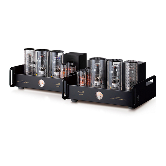
INTRODUCING THE M-2500 PX25/300B/KT150 PUSH-PULL MONOBLOCK POWER AMPLIFIERS The M-2500 monoblock power amplifiers are Allnic Audio’s top of the line, power tube flexible, push- pull monoblock power amplifier model. Like all Allnic Audio products, the M-2500s have Permalloy (iron and nickel alloy) for their transformer cores. Allnic is grateful to Mr. G.W. Elmen of Western Electric for inventing Permalloy for transformer core use, and in so doing, providing an enormous service to recorded music listeners everywhere. -
Page 5: What's In The Box
Fig.3 Square Wave 20KHz* Measured by LEADER LAG-126 Audio Signal Generator and KENWOOD CS-4125 Oscilloscope. • As are all Allnic Audio products, the M-2500s are fully RoHS (EU Reduction of Hazardous Substances regulation) compliant in construction and materials. WHAT’S IN THE BOX? Please check that each shipping box contains the following: •... -
Page 6: Safety
INITIAL SET-UP LOCATION, LOCATION, LOCATION Like all audio products using tubes, the Allnic Audio M-2500s need to be placed on a solid stand in a location that provides good air circulation around, above and below the monoblocks. • DO NOT cover the tops of the M-2500s. -
Page 7: Inputs
(facing the back) rear of the chassis, with the balanced input closest to the side edge. The inputs are on the left rear of the chassis on the other M-2500. Between the inputs, there is a switch to select one of two pin configurations for a balanced cable (i.e., it changes the phase). -
Page 8: Power Connection
Connect the input interconnect and speaker cables before you insert the power cable into the receptacle at the left (facing the back) rear of the chassis on one M-2500, and on the right on the other (See Figure 6). The M-2500s use a standard 15 amp three prong male IEC connection for AC input. -
Page 9: Tubes And Tube Bias
TUBES AND TUBE BIAS Each M-2500 monoblock uses the following tubes (See Figure 8): • Two (2) x PX25/300B/KT150 • One (1) x 6485 and two (2) x 12A4 (300B version) •... -
Page 10: Specifications
All consequences of changing or attempting to change tubes are borne by the user unless by express agreement between the owner and an authorized Allnic representative. Allnic Audio and its authorized representatives are not liable in any way whatsoever for any injury or loss incurred by the user or for damage to the M-2500s, any of their parts, or tubes or replacement tubes resulting from the user changing or attempting to change tubes. -
Page 11: Warranty
Date of purchase is the date indicated on the invoice for the product issued by Allnic Audio or its authorized representative. For the warranty to be valid, a defective product must be returned to Allnic Audio’s authorized representative for service prior to any unauthorized attempt to repair. - Page 12 FIGURES The monoblocks are mirror images of each other. Figure 4: M-2500 Side View - Switch...
- Page 13 Figure 5: M-2500 Opposite Side View...
- Page 14 Figure 6: M-2500 – Rear View...
- Page 15 Figure 7: M-2500 – Front View...
- Page 16 Figure 8: M-2500 – Top View...
Need help?
Do you have a question about the M-2500 and is the answer not in the manual?
Questions and answers