Table of Contents
Advertisement
Quick Links
V266DMU/V266DM
USER'S MANUAL
M/B For Socket-A Athlon/Duron Processor
NO. G03-V266DMU
Rev:1.0
Release date: November 2003
Trademark:
* Specifications and Information contained in this documentation are furnished for information use only, and are
subject to change at any time without notice, and should not be construed as a commitment by manufacturer.
Advertisement
Table of Contents

Related Manuals for JETWAY V266DMU


Summary of Contents for JETWAY V266DMU
- Page 1 V266DMU/V266DM USER'S MANUAL M/B For Socket-A Athlon/Duron Processor NO. G03-V266DMU Rev:1.0 Release date: November 2003 Trademark: * Specifications and Information contained in this documentation are furnished for information use only, and are subject to change at any time without notice, and should not be construed as a commitment by manufacturer.
-
Page 2: Table Of Contents
USER’S NOTICE ................ii MANUAL REVISION INFORMATION ..........1 COOLING SOLUTIONS ..............1 CHAPTER 1 INTRODUCTION OF V266DMU/V266DM MOTHERBOARD 1-1 FEATURE OF MOTHERBOARD............... 2 1-2 SPECIFICATION ..................3 1-3 PERFORMANCE LIST ................4 1-4 LAYOUT DIAGRAM & JUMPER SETTING ........... 5 CHAPTER 2 HARDWARE INSTALLATION 2-1 HARDWARE INSTALLATION STEPS ............. -
Page 3: User's Notice
MAY BE REPRODUCED, TRANSMITTED OR TRANSLATED INTO ANY LANGUAGE IN ANY FORM OR BY ANY MEANS WITHOUT WRITTEN PERMISSION OF MANUFACTURER. THIS MANUAL CONTAINS ALL INFORMATION REQUIRED TO USE V266DMU/ V266DM MOTHER-BOARD AND WE DO ASSURE THIS MANUAL MEETS USER’S REQUIREMENT BUT WILL CHANGE, CORRECT ANY TIME WITHOUT NOTICE. -
Page 4: Manual Revision Information
Cable for IDE/Floppy CD for motherboard utilities Cable for USB Port 3/4 (Option) □ V266DMU/V266DM User’s Manual AMD Athlon™ / Duron™ Processor Family Cooling Solutions As processor technology pushes to faster speeds and higher performance, thermal management becomes increasingly crucial when building computer systems. -
Page 5: Chapter 1 Introduction Of V266Dmu/V266Dm Motherboard
With USB control as well as capability of expanding to four USB2.0 function ports in V266DMU (four USB1.1 function ports in V266DM) meet future USB demand also this motherboard has built-in hardware monitor function. This will monitor and protect your computer. Power Fail Recovery function for system auto power on after power recovery. -
Page 6: Performance List
Spec Description ∗ ATX form factor 4 layers PCB size: 30.5x21.0cm Design ∗ VIA KT266A/VT8235 Chipset for V266DMU Chipset ∗ VIA KT266A/VT8233A Chipset for V266DM ∗ Support AMD Athlon 700MHz∼1.4GHz processor CPU Socket ∗ Support AMD Duron 600MHz∼1.3GHz processor ∗ Support AMD Athlon XP1500+~XP2600+ processor ∗... -
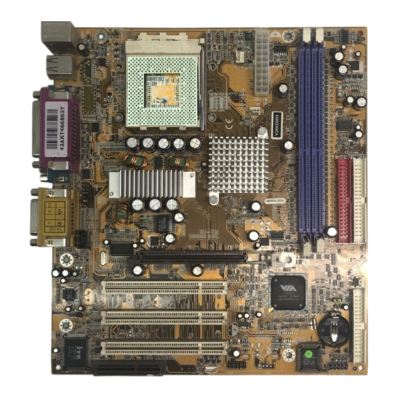
Page 7: Layout Diagram & Jumper Setting
The following performance data list is the testing result of some popular benchmark testing programs. These data are just referred by users, and there is no responsibility for different testing data values gotten by users (the different Hardware & Software configuration will result in different benchmark testing results.) Performance Test Report AMD Athlon XP 2000+... - Page 8 PRINT GAME/MIDI PORT PS/2 Mouse PS/2 Keyboard COM1 COM2 LINE-IN LINE-OUT K/B Power ON Jumper (JP1) CPU Socket CPU FAN PS2 KB/Mouse Port ATX Power Connector USB Port FAN2 DDR Socket X2 PC99 Back Panel VIA KT266A Chip ATA 133 IDE Connector Front Panel Audio CD Audio...
-
Page 9: Chapter 2 Hardware Installation
JBAT CMOS RAM Clear 3-pin Block Keyboard Power On Enable/Disabled 3-pin Block Connectors Connector Name Description Page ATXPOW ATX Power Connector 20-pin Block P.12 KB/MS PS/2 Mouse & PS/2 Keyboard 6-pin Female P.12 Connector USB Port Connector 4-pin Connector P.12 PARALL Parallel Port Connector 25-pin Female... -
Page 10: Hardware Installation Steps
2-1 Hardware installation Steps Before using your computer, you had better complete the following steps: 1. Check motherboard setting 2. Install CPU 3. Install Memory 4. Install Expansion cards 5. Connect Ribbon cables, Panel wires, and power supply 6. Setup BIOS 7. -
Page 11: Install Cpu
JBAT JBAT 1-2 closed Normal 2-3 closed Clear CMOS CMOS RAM Clear Setting 3. Keyboard Power On function Enabled/Disabled: JP1 When setting Enabled you can using keyboard by key in password to power on system. 1-2 closed K/B Power ON Disable 2-3 closed K/B Power ON Enabled (Default) -
Page 12: About Amd Athlon & Duron 462-Pin Cpu
BIOS (Basic Input/Output System) - the program logic used to boot up a computer and establish the relationship between the various components. Driver - software, which defines the characteristics of a device for use by another device or other software. Processor - the "central processing unit"... -
Page 13: Install Memory
2-4 Install Memory This motherboard provides 184-pin DUAL INLINE MEMORY MODULES (DIMM) sites for memory expansion available from minimum memory size of 64MB to maximum memory size of 2.0GB DDR SDRAM. Valid Memory Configurations Bank 184-Pin DIMM Total Memory Bank 0, 1 (DDR1) DDR200/DDR266 DDR SDRAM 64MB∼1.0GB Bank 2, 3 (DDR2) -
Page 14: Procedure For Expansion Card Installation
2. Remove your computer’s cover and the bracket plate on the slot you intend to use. 3. Align the card’s connectors and press firmly. 4. Secure the card on the slot with the screen you remove above. 5. Replace the computer system’s cover. 6. -
Page 15: Agp Slot
2-5-4 AGP Slot This motherboard provides an AGP Slot, support the 1X/2X/4X AGP VGA card. AG P SLO T 2-6 Connectors, Headers 2-6-1 Connectors Power Connector (20-pin block) : ATXPOW ATX Power Supply connector. This is a new defined 20-pins connector that usually comes with ATX case. - Page 16 D-Subminiature Receptacle Connector for joystick/MIDI Device. Line-out : Audio output to speaker Line-in : Audio input to sound chip MIC : Microphone Connector For joystick or MIDI Device Game/MIDI : Serial Port COM1, COM2 : COM1, COM2 COM1, COM2 are the 9-pin D-Subminiature mail connector. The On-board serial port can be disabled through BIOS SETUP.
- Page 17 IDE 1 Pin 1 Primary IDE Connector Secondary IDE Connector (40-pin block): IDE2 This connector connects to the next set of Master and Slave hard disks. Follow the same procedure described for the primary IDE connector. You may also configure two hard disks to be both Masters using one ribbon cable on the primary IDE connector and another ribbon cable on the secondary IDE connector.
-
Page 18: Headers
2-6-2 Headers (1) Line-In/Out, MIC Header (9-pin): AUDIO This header connect to Front Panel Line-In, Line-out, MIC connector with cable. AUDIO Pin 1 AUD _ MIC AUD _ G ND AUD _ VCC AUD _ MIC _ BIAS AUD _ R ET _ R AUD _ FPO UT _ R HP _ O N AUD _ RET _ L... - Page 19 Power switch: PWR BTN This 2-pin connector connects to the case-mounted power switch to power ON/OFF the system. JW _ FP SPEAK Pin 1 Pin 1 System Case Connections Wake On-LAN Headers (3-pin) : WOL This connector connects to a LAN card with a WAKE ON-LAN output. This connector power up the system when a wake up signal is received through the LAN card.
- Page 20 (11) IR infrared module Headers (5-pin) : IR This connector supports the optional wireless transmitting and receiving infrared module. You must configure the setting through the BIOS setup to use the IR function. Pin 1 IR infrared module Headers (12) CD Audio-In Headers (4-pin) : CDIN CDIN is the connector for CD-Audio Input signal.
-
Page 21: Starting Up Your Computer
2-7 Starting Up Your Computer 1. After all connection are made, close your computer case cover. 2. Be sure all the switch are off, and check that the power supply input voltage is set to proper position, usually in-put voltage is 220V∼240V or 110V∼120V depending on your country’s voltage used. -
Page 22: Chapter 3 Introducing Bios
Chapter 3 Introducing BIOS The BIOS is a program located on a Flash Memory on the motherboard. This program is a bridge between motherboard and operating system. When you start the computer, the BIOS program gain control. The BIOS first operates an auto-diagnostic test called POST (power on self test) for all the necessary hardware, it detects the entire hardware device and configures the parameters of the hardware synchronization. -
Page 23: The Main Menu
3-3 The Main Menu Once you enter Award BIOS CMOS Setup Utility, the Main Menu (Figure 3-1) will appear on the screen. The Main Menu allows you to select from fourteen setup functions and two exit choices. Use arrow keys to select among the items and press <Enter> to accept or enter the sub-menu. -
Page 24: Standard Cmos Features
Load Optimized Defaults Use this menu to load the BIOS default values that are factory settings for optimal performances system operations. Load Standard Defaults Use this menu to load the BIOS default values for the minimal/stable performance system operation. Set Supervisor/User Password Use this menu to set User and Supervisor Passwords. -
Page 25: Advanced Bios Features
The time format is <hour><minute><second>. Primary Master/Primary Slave Secondary Master/Secondary Slave Press PgUp/<+> or PgDn/<–> to select Manual, None, Auto type. Note that the specifications of your drive must match with the drive table. The hard disk will not work properly if you enter improper information for this category. - Page 26 Allows you to choose the VIRUS Warning feature for IDE Hard Disk boot sector protection. If this function is enabled and someone attempt to write data into this area, BIOS will show a warning message on screen and alarm beep. Disabled (default) No warning message to appear when anything attempts to access the boot sector or hard disk partition table.
-
Page 27: Advanced Chipset Features
Keystrokes repeat at a rate determined by the keyboard controller. When enabled, the typematic rate and typematic delay can be selected. The settings are: Enabled/Disabled. Typematic Rate (Chars/Sec) Sets the number of times a second to repeat a keystroke when you hold the key down. The settings are: 6, 8, 10, 12, 15, 20, 24, and 30. -
Page 28: Dram Timing Settings
Please refer to section 3-6-1 AGP Timing Settings Please refer to section 3-6-2 PCI Timing Settings Please refer to section 3-6-3 System BIOS Cacheable Selecting Enabled allows caching of the system BIOS ROM at F0000h-FFFFFh, resulting in better system performance. However, if any program writes to this memory area, a system error may result. -
Page 29: Agp Timing Settings
If an insufficient number of cycles is allowed for the RAS to accumulate its charge before DRAM refresh, the refresh may be incomplete and the DRAM may fail to retain date. Fast gives faster performance; and Slow gives more stable performance. This field applies only when synchronous DRAM is installed in the system. -
Page 30: Integrated Peripherals
CMOS Setup Utility – Copyright(C) 1984-2003 Award Software Integrated Peripherals > OnChip IDE Function Press Enter Item Help > OnChip Device Function Press Enter > Onboard Super IO Function Press Enter Init Display First PCI Slot Menu Level > ↑↓→← Move Enter:Select +/-/PU/PD:Value F10:Save ESC:Exit F1:General Help F5:Previous Values F6:Optimized Defaults... -
Page 31: Onchip Device Function
The integrated peripheral controller contains an IDE interface with support for two IDE channels. Select Enabled to activate each channel separately. The settings are: Enabled and Disabled. Primary/Secondary Master/Slave PIO The four IDE PIO (Programmed Input/Output) fields let you set a PIO mode (0-4) for each of the four IDE devices that the onboard IDE interface supports. -
Page 32: Onchip Super Io Function
This item allows you to decide to enable/disable the chipset family to support AC97 Modem. The settings are: Auto, Disabled. USB Host Controller Select Enabled if your system contains a Universal Serial Bus (USB) controller and you have a USB peripherals. The settings are: Enabled, Disabled. USB Keyboard Support Select Enabled if your system contains a Universal Serial Bus (USB) controller and you have a USB keyboard. -
Page 33: Power Management Setup
: Standard Parallel Port : Enhanced Parallel Port : Extended Capability Port SPP/EPP/ECP/ECP+EPP To operate the onboard parallel port as Standard Parallel Port only, choose “SPP.” To operate the onboard parallel port in the EPP modes simultaneously, choose “EPP.” By choosing “ECP”, the onboard parallel port will operate in ECP mode only. -
Page 34: Wake Up Events
This determines the IRQ in which the MODEM can use. The settings are: 3, 4, 5, 7, 9, 10, 11, NA. Power Button Function Pressing the power button for more than 4 seconds forces the system to enter the Soft-Off state. The settings are: Delay 4 Sec, Instant-Off. -
Page 35: Pnp/Pci Configuration Setup
CMOS Setup Utility – Copyright(C) 1984-2003 Award Software IRQs Activities Primary INTR Item Help IRQ3 (COM 2) Enabled IRQ4 (COM 1) Enabled IRQ5 (LPT 2) Enabled Menu Level >>> IRQ6 (Floppy Disk) Enabled IRQ7 (LPT 1) Enabled IRQ8 (RTC Alarm) Disabled IRQ9 (IRQ2 Redir) -
Page 36: Irq Resources
by a “>”). The settings are: Auto(ESCD), Manual. IRQ Resources When resources are controlled manually, assign each system interrupt a type, depending on the type of device using the interrupt. Please refer to section 3-9-1 PCI/VGA Palette Snoop Leave this field at Disabled. The settings are Enabled, Disabled. 3-9-1 IRQ Resources CMOS Setup Utility –... -
Page 37: Miscellaneous Control
This item can let users setting the Shutdown temperature, when CPU temperature over this setting the system will auto shutdown to protect CPU. Show PC Health in Post During Enabled, it displays information list below. The choice is either Enabled or Disabled Current CPU Temperature/Current System Temp/Current FAN1, FAN2 Speed/Vcore/ Vdd/3.3V/+5V/+12V/-12V/VBAT(V)/5VSB(V) This will show the CPU/FAN/System voltage chart and FAN Speed. -
Page 38: Load Standard/Optimized Defaults
Load Standard Defaults When you press <Enter> on this item, you get confirmation dialog box with a message similar Load Standard Defaults (Y/N)? N Pressing <Y> loads the BIOS default values for the most stable, minimal-performance system operations. Load Optimized Defaults When you press <Enter>... -
Page 39: Chapter 4 Driver & Free Program Installation
DRIVER & FREE PROGRAM INSTALLATION Check your package and there is A MAGIC INSTALL CD included. This CD consists of all DRIVERS you need and some free application programs and utility programs. In addition, this CD also include an auto detect software which can tell you which hardware is installed, and which DRIVERS needed so that your system can function properly. -
Page 40: Install Via Service Pack 4 In 1 Driver
IDE : VIA ATAPI VENDOR SUPPORT DRIVER IS USED TO FIXED COMPATIBILITY ISSUE FOR IDE DEVICES AGPVXD : VIA AGPVXD DRIVER IS TO BE INSTALLED, IF YOU ARE USING AN AGP VGA CARD, VIAGART.VXD WILL PROVIDE SERVICE ROUTINES TO YOUR VGA DRIVER AND INTERFACE DIRECTLY TO HARDWARE, PROVIDING FAST GRAPHIC ACCESS IRQ ROUTING : VIA PCI IRQ MINIPORT DRIVER IS TO BE INSTALLED UNDER WIN98... - Page 41 5. Click NEXT to Install ATAPI Vender 6. Click NEXT to choose enabled DMA Mode Support Driver 7. Click NEXT to Install VIA AGP VXD Driver 8. Click NEXT to Install VIA IRQ Routing Mini port Driver 9. Click Finish to restart computer...
-
Page 42: Sound
4-2 SOUND Install ALC Audio Codec Driver 1. Click SOUND when MAGIC INSTALL 2. Click NEXT install sound driver MENU appears 3. Click Finish and Restart Computer 4. Avance Audio Rack table can play CD,WAV,MID,MP3,AVI,MPG format file 5. Sound Effect select and KaraOK Mode 6. -
Page 43: Pc-Health
4-3 PC-HEALTH Winbond Hardware Doctor Monitoring Software The path of the file is X:\VIA\HEALTH-W\SETUP.EXE (Only support WINDOWS 95/98/98SE/ME) In Windows 95/98 Winbond Hardware Doctor Monitoring Software needs some system files to copy in Utility that’s why it needs install PC-HEALTH twice to complete setup. 1. -
Page 44: Magic Bios Install Bios Live Update Utility
4-4 MAGIC BIOS Install BIOS Live Update Utility Click Magic BIOS when Magic Install Click Next to install the Magic BIOS in MENU appears Destination Folder After finish Setup you will have a Magic Double click the Magic BIOS icon you will BIOS icon in your screen have this picture, choose from internet you can upgrade BIOS On-line... -
Page 45: Pc-Cillin Install Pc-Cillin2002 Anti-Virus Program
When choose From Local Driver to update 10. Choose the correct BIOS file to update BIOS BIOS, you must have the correct BIOS file in your Local Driver 4-5 PC-CILLIN Install PC-CILLIN 2002 Anti-virus program 1. Click PC-CILLIN when MAGIC INSTALL 2. - Page 46 5. Click INSTALL, Start to install the software 6. Setup Complete and click FINISH 7. After PC-CILLIN 2002 complete, Please 8. finish register process, we recommend select register your information and get LICENSE update item to download newest engine code KEY from TREND MICRO web site, enter and virus code your license key and click FINISH...
-
Page 47: Usb2.0
4-6 USB2.0 Install VIA USB2.0 DEVICE DRIVER 1. Click USB2.0 when MAGIC INSTALL 2. When USB2.0 Setup Program Appear, Click MENU Appear NEXT Note: Please Install Microsoft Service Pack 1 in Windows XP OS Before you Install VIA USB2.0 Device Driver. 3. -
Page 48: How To Disable On-Board Sound
You may copy from DRIVER CD X:\FLASH\AWDFLASH.EXE or download from our web site. STEP 3. Copy latest BIOS for V266DMU from our web site to your boot disc. STEP 4. Insert your boot disc into A:, start the computer, type “Awdflash A:\V266DMAxxx.BIN /SN/PY/CC/R”...
Need help?
Do you have a question about the V266DMU and is the answer not in the manual?
Questions and answers