Table of Contents
Advertisement
Quick Links
Advertisement
Table of Contents

Related Manuals for Mosebach HX150


Summary of Contents for Mosebach HX150
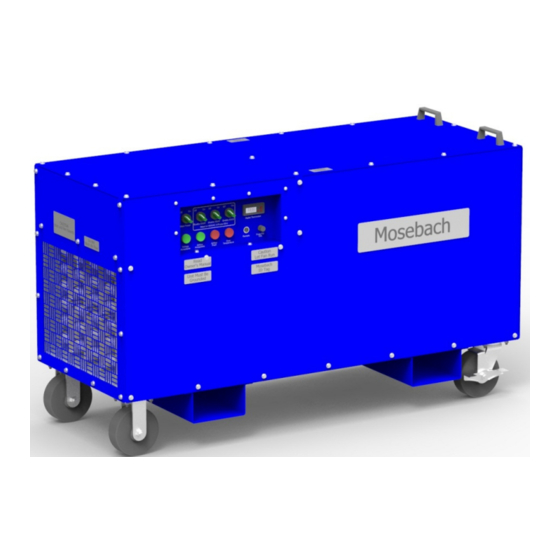
- Page 1 HX150 OPERATOR’S MANUAL 150 kW HEATER...
-
Page 2: Table Of Contents
Table of Contents RECEIVING ............................3 INSPECTING ............................3 LIFTING AND MOVING ......................... 3 SAFETY SYMBOLS ..........................4 SYMBOL MEANING ..........................4 SAFETY ..............................5 DEFINITIONS............................6 POWER AND GROUND CONNECTIONS ..................... 7 AIR INTAKES AND EXHAUST PORTS ..................... 7 INTAKE AND EXHAUST DUCTING ...................... -
Page 3: Receiving
READ ALL INSTUCTIONS! WARNING: This unit operates with high voltage and has the ability to produce extreme temperatures. Failure to follow all instructions shown in this manual may result in serious injury or death. RECEIVING INSPECTING 1. Check the exterior of the shipping container or packaging material for obvious damage. -
Page 4: Safety Symbols
SAFETY SYMBOLS The purpose of safety symbols is to attract your attention to possible dangers. The safety symbols and the explanations with them deserve your careful attention and understanding. The symbol warnings do not, by themselves, eliminate any danger. The instructions and warnings they give are no substitutes for proper accident prevention measures. -
Page 5: Safety
To reduce risk of injury to persons or damage to the CAUTION – unit, remove objects that can be moved by the Blown Debris cooling fans of the unit. WARNING – This unit can potentially operate at high voltage Electrical and current. -
Page 6: Definitions
Extreme caution is necessary when any heater is used by or near children or invalids and whenever the heater is left operating and unattended. Always unplug heater when not in use. Do not operate any heater with a damaged cord or plug or after the heater malfunctions or has been dropped or damaged in any manner. -
Page 7: Power And Ground Connections
POWER AND GROUND CONNECTIONS Customer Cam-Lock Ground Connections WARNING: ELECTRIC SHOCK HAZARD. All power connections must be connected or covered. Failure to do so will expose operators to possible shock and the possibility of grounding-out or shorting-out of the test power source. All power connections must be covered or connected. -
Page 8: Intake And Exhaust Ducting
Some important considerations when installing ducting with your heater: Only use ducting that can connect to the intake or exhaust adapters designed by Mosebach Manufacturing. Other adapter designs may allow you to connect incorrectly sized ducting which may result in heater failure. -
Page 9: Exhaust Temperature
EXHAUST TEMPERATURE WARNING: FIRE AND BURN HAZARD. Keep flammable material at least 40 feet away from the Heater. A great deal of heat is expelled from the Heater. Temperatures inside the Heater are sufficient to ignite flammable fumes or materials. Failure to maintain proper housekeeping and properly securing flammable material could lead to fire, burns, and/or injury. -
Page 10: Operation
20” flexible duct. Optional Exhaust and Intake duct transitions for 20” flexible duct. Equipment Wired remote temperature control with thermistor ports. Unit Weight 450 lbs. Outer-Most 57 7/16” x 22 5/8” x 34 5/16” without duct transitions. Dimensions OPERATION PRE-STARTUP Check housekeeping in the operational area and correct all unsafe conditions. -
Page 11: Remote Operation
REMOTE OPERATION An option available for the HX150 is a remote thermostat. Ensure that when a remote thermostat is used that the thermostat is completely within the enclosure that is to be heated. If the remote thermostat is not within the enclosure to be heated, then another means of monitoring and controlling temperature must be used. -
Page 12: Shutdown
• When placing the remote thermostat, keep it ten feet from the unit and not in the direct exhaust of the unit. SHUTDOWN Place all of the Heating Power switches in the OFF position. Allow fan to operate at least 3 minutes or until exhaust air is cool before shutting Main Power switch off. -
Page 13: Replacing Fuses
Control Fuses REPLACING FUSES ¼”-20 Hex Head Screws Step Fuses Screw 1. Loosen the 17 hex head screws that secure the lid of the load bank. Remove all 17 screws. 2. Remove the lid, as shown in Figure 3A. 3. Locate the defective fuse. All internal step and control fuses are located in the area called out in figure 3B. -
Page 14: Replacing Resistors
REPLACING RESISTORS Contact Mosebach Manufacturing Co. PREVENTATIVE MAINTENANCE OF HEATER NOTICE: Do not use a power washer to clean off the exterior of the unit. It is high voltage electrical equipment. Component Action Frequency Entire Unit Walk around the load bank and... -
Page 15: Optional Equipment
OPTIONAL EQUIPMENT Description Part Number 20” Ø Exhaust Transition FR-0400-0419 20” Ø Intake Transition FR-0400-0421 25’ Long 20” Ø Duct HW-9000-0730 Remote Control Kit RC-HX60... -
Page 16: Service Parts
SERVICE PARTS Mosebach Part Part Description Part Label Number Fan - 450mm BLWR-0055-0113 Fuse 5A Type CC FVSA, FVSB EC-9500-0245 Fuse 1A Type CC FVSC EC-9500-0247 Fuse 25A Type CC FBA, FBB, FBC EC-9500-0307 Fuse 15A, 1l4 x 1-1l4 EC-9500-1971 Fuse 80A Class "T"... - Page 17 Initial Release 10/27/16 Rev. Description Rev. By Date Copyright © 2016 Mosebach Manufacturing Company MOSEBACH MANUFACTURING COMPANY 1417 McLaughlin Run Road • Pittsburgh, PA 15241-3103 USA T: 412.220.0237 Customer Care F: 412-220-0236 www.mosebachresistors.com OM-HX150.docx 10/27/2016 “SAVE THESE INSTRUCTIONS”...
Need help?
Do you have a question about the HX150 and is the answer not in the manual?
Questions and answers