Table of Contents
Advertisement
Quick Links
Advertisement
Table of Contents

Related Manuals for Mosebach HX60-W


Summary of Contents for Mosebach HX60-W
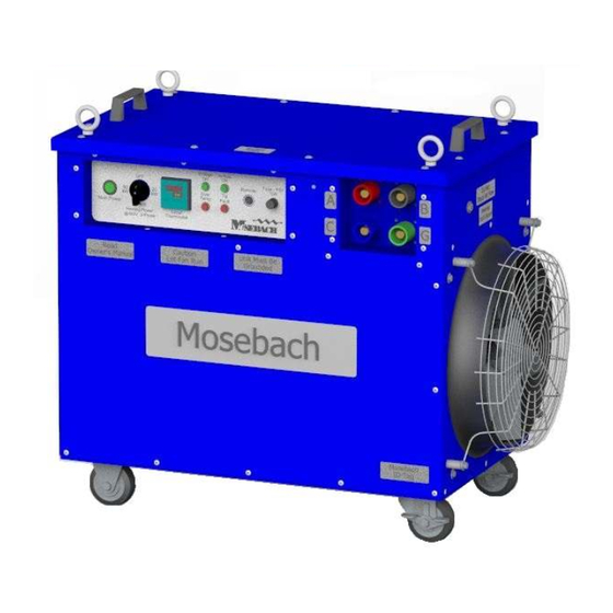
- Page 1 HX60-W HX60-B HX60-G OPERATOR’S MANUAL 60 kW HEATER...
-
Page 2: Table Of Contents
Table of Contents RECEIVING ............................3 INSPECTING ............................3 LIFTING AND MOVING ......................... 3 SAFETY SYMBOLS ..........................4 SYMBOL MEANING ..........................4 SAFETY ..............................5 DEFINITIONS............................6 POWER AND GROUND CONNECTIONS ..................... 7 AIR INTAKES AND EXHAUST PORTS ..................... 7 INTAKE AND EXHAUST DUCTING ...................... -
Page 3: Receiving
READ ALL INSTUCTIONS! WARNING: This unit operates with high voltage and has the ability to produce extreme temperatures. Failure to follow all instructions shown in this manual may result in serious injury or death. RECEIVING INSPECTING 1. Check the exterior of the shipping container or packaging material for obvious damage. -
Page 4: Safety Symbols
SAFETY SYMBOLS The purpose of safety symbols is to attract your attention to possible dangers. The safety symbols and the explanations with them deserve your careful attention and understanding. The symbol warnings do not, by themselves, eliminate any danger. The instructions and warnings they give are no substitutes for proper accident prevention measures. -
Page 5: Safety
To reduce risk of injury to persons or damage to the CAUTION – unit, remove objects that can be moved by the Blown Debris cooling fans of the unit. WARNING – This unit can potentially operate at high voltage Electrical and current. -
Page 6: Definitions
Extreme caution is necessary when any heater is used by or near children or invalids and whenever the heater is left operating and unattended. Always unplug heater when not in use. Do not operate any heater with a damaged cord or plug or after the heater malfunctions or has been dropped or damaged in any manner. -
Page 7: Power And Ground Connections
POWER AND GROUND CONNECTIONS Customer Cam-Lock Ground Connections WARNING: ELECTRIC SHOCK HAZARD. All power connections must be connected or covered. Failure to do so will expose operators to possible shock and the possibility of grounding-out or shorting-out of the test power source. All power connections must be covered or connected. -
Page 8: Intake And Exhaust Ducting
Some important considerations when installing ducting with your heater: Only use ducting that can connect to the intake or exhaust adapters designed by Mosebach Manufacturing. Other adapter designs may allow you to connect incorrectly sized ducting which may result in heater failure. -
Page 9: Exhaust Temperature
EXHAUST TEMPERATURE WARNING: FIRE AND BURN HAZARD. Keep flammable material at least 40 feet away from the Heater. A great deal of heat is expelled from the Heater. Temperatures inside the Heater are sufficient to ignite flammable fumes or materials. Failure to maintain proper housekeeping and properly securing flammable material could lead to fire, burns, and/or injury. -
Page 10: Operation
14” or 20” flexible duct. Optional Exhaust duct transition for 14” or 20” flexible duct. Equipment Wired remote temperature control with thermocouple ports. Unit Weight 180 lbs. Outer-Most 30 5/16” x 18 13/16” x 34.36” without fork channels or duct transition. Dimensions OPERATION PRE-STARTUP... -
Page 11: Remote Operation
Air should be coming from the exhaust port and the green air flow light should come on. Check to see that only green lamps are lit. Operating heater with flickering green lamp will lead to damage. NOTICE: If you apply a voltage that is higher than the Heater is designed to handle, it will fail. -
Page 12: Shutdown
• Using one thermocouple will control heater based on the local temperature of that thermocouple. • Using two thermocouples will control heater based on the average of the two local temperatures of thermocouples. • When placing thermocouple(s), keep ten feet from the unit and not in direct exhaust. -
Page 13: Replacing Fuses
This is an indication that the internal cabinet temperature has exceeded 150°F. Over Temperature Make sure the cabinet is ventilated. Light Check over temperature sensors (OTS) see figure 4. This indicates the unit is not level. Tip Fault Light Do not try to operate unit while tipped or tilted more than 15° from horizontal. The heater has a built in voltage sensing system to protect itself. -
Page 14: Replacing Resistors
REPLACING RESISTORS Contact Mosebach Manufacturing Co. PREVENTATIVE MAINTENANCE OF HEATER NOTICE: Do not use a power washer to clean off the exterior of the unit. It is high voltage electrical equipment. -
Page 15: Optional Equipment
secure to their mounting plate. Check the fan for damage that Check Annually could cause the airflow to change such as damaged or missing bearing, or damaged blades. Contactors Ensure contacts are opening and Check Annually closing OPTIONAL EQUIPMENT Description Part Number 14”... -
Page 16: Service Parts
Swivel = HW-0900-0609 Initial Release 11/6/15 Rev. Description Rev. By Date Copyright © 2015 Mosebach Manufacturing Company MOSEBACH MANUFACTURING COMPANY 1417 McLaughlin Run Road • Pittsburgh, PA 15241-3103 USA T: 412.220.0237 Customer Care F: 412-220-0236 www.mosebachresistors.com OM-HX60.docx November 6 , 2015...
Need help?
Do you have a question about the HX60-W and is the answer not in the manual?
Questions and answers