
Related Manuals for Kramer RC-53DLC


Summary of Contents for Kramer RC-53DLC
- Page 1 Vertrieb von CAMBOARD Electronics Kramer Electronics, Ltd. USER MANUAL Model: RC-53DLC K-NET™ Auxiliary Control Panel www.camboard.de Tel. 07131 911201 ce-info@camboard.de Fax 07131 911203...
- Page 2 im Vertrieb von CAMBOARD Electronics www.camboard.de Tel. 07131 911201 ce-info@camboard.de Fax 07131 911203...
-
Page 3: Table Of Contents
Table 1: RC-53DLC K-NET™ Auxiliary Control Panel – Front Panel Features Table 2: RC-53DLC K-NET™ Auxiliary Control Panel – Rear Panel Features Table 3: Grounding Component Descriptions Table 4: The Commands Configuration Table 5: Technical Specifications of the RC-53DLC K-NET™ Auxiliary Control Panel 10 www.camboard.de Tel. 07131 911201 ce-info@camboard.de... -
Page 4: Introduction
GROUP 8: Cables and Connectors; GROUP 9: Room Connectivity; GROUP 10: Accessories and Rack Adapters; GROUP 11: Sierra Products 2 K-NET is a proprietary Kramer protocol for communication between Kramer products 3 The guide provides information about how to set up the system and is updated on a regular basis. For the latest online guide, go to http://www.kramerelectronics.com... -
Page 5: Achieving The Best Performance
Kramer Electronics has made arrangements with the European Advanced Recycling Network (EARN) and will cover any costs of treatment, recycling and recovery of waste Kramer Electronics branded equipment on arrival at the EARN facility. For details of Kramer’s recycling arrangements in your particular country go to our recycling pages at http://www.kramerelectronics.com/support/recycling/. -
Page 6: Overview
Vertrieb von CAMBOARD Electronics Overview Overview The RC-53DLC is an auxiliary remote control panel for Master Room Controllers for control of A/V equipment in a room. The RC-53DLC: • Features six front panel, backlit buttons designed in two groups; one group of two buttons, and another group of four buttons •... -
Page 7: Figure 2: Rc-53Dlc K-Net™ Auxiliary Control Panel - Rear Panel
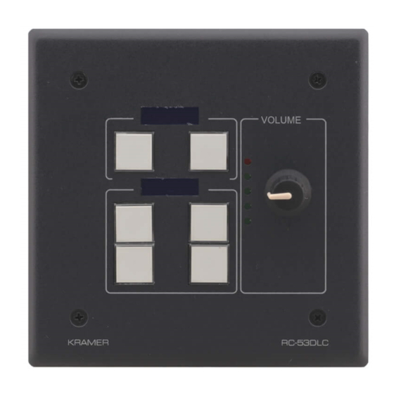
Vertrieb von CAMBOARD Electronics Defining the RC-53DLC Table 1: RC-53DLC K-NET™ Auxiliary Control Panel – Front Panel Features Feature Function SOURCE Buttons Group of four programmable, backlit buttons Faceplate Screws Four screws connecting the faceplate to the Rear Box “DISPLAY”... -
Page 8: Grounding The Rc-53Dlc
1/8" Toothed Lock Washer M3 Ring Tongue Terminal Figure 3: Grounding Connection Components To ground the RC-53DLC: 1. Connect the Ring Tongue terminal to the building grounding point wire (it is recommended to use a green-yellow AWG#18 (0.82mm ) wire, crimped with a proper hand-tool). -
Page 9: Using The Rc-53Dlc K-Net™ Auxiliary Control Panel
• The auxiliary panel can be programmed only via the Master Room controller (for example, the Kramer SV-551 SummitView™ Processor/Switcher) Figure 4: RC-53DLC connected to the SV-551 SummitView™ Processor / Switcher 1 By authorized Kramer technical personnel or by an external system integrator 2 Power supplies are sold separately. -
Page 10: Installing The Rc-53Dlc Faceplate, Button Caps And Labels
Vertrieb von CAMBOARD Electronics Installing the RC-53DLC Faceplate, Button Caps and Labels Installing the RC-53DLC Faceplate, Button Caps and Labels This section describes how to install the faceplate, button caps and labels. Figure 5 illustrates a sample button label sheet. -
Page 11: Figure 8: Placing The Button Cap
6. Remove the protective foils from both sides of the Perspex (acrylic glass) windows. 7. Remove the protective foils from both displays. 8. Place the faceplate on the RC-53DLC so that the four screw mounting holes are aligned. 9. Insert the four mounting screws and tighten with a screwdriver. -
Page 12: Operating The Rc-53Dlc K-Net™ Auxiliary Control Panel
Vertrieb von CAMBOARD Electronics Operating the RC-53DLC K-NET™ Auxiliary Control Panel Operating the RC-53DLC K-NET™ Auxiliary Control Panel In the following example (illustrated in Figure 9), the auxiliary control panel is labeled with specific functions and each button is programmed... -
Page 13: Technical Specifications
Technical Specifications Technical Specifications Table 5 defines the technical specifications. Table 5: Technical Specifications1 of the RC-53DLC K-NET™ Auxiliary Control Panel PORTS: 2 K-NET on terminal block connectors; 1USB connector, 1 RS-232 on terminal block connector (factory use only) POWER SOURCE:... - Page 14 im Vertrieb von CAMBOARD Electronics www.camboard.de Tel. 07131 911201 ce-info@camboard.de Fax 07131 911203...
- Page 15 Vertrieb von CAMBOARD Electronics For the latest information on our products and a list of Kramer distributors, visit our Web site www.kramerelectronics.com where updates to this user manual may be found. We welcome your questions, comments and feedback. Safety Warning: Disconnect the unit from the power supply before opening/servicing.
Need help?
Do you have a question about the RC-53DLC and is the answer not in the manual?
Questions and answers