
Related Manuals for Kramer RC-712M


Summary of Contents for Kramer RC-712M
- Page 1 K R A ME R E LE CT R O N IC S L TD . USER MANUAL MODEL: RC-76M/RC-712M P/N: 2900-300329 Rev 3...
-
Page 3: Table Of Contents
Operating the RC-76M/RC-712M Front Panel Button Labels Technical Specifications Figures Figure 1: RC-76M/RC-712M Room Controller – Front Panel Figure 2: RC-76M/RC-712M Room Controllers – Rear Panel Figure 3: Merten Compatible Housing Figure 4: Connecting the RC-712M Figure 5: K-NET PINOUT Connection... -
Page 4: Introduction
Scan Converters and Scalers; GROUP 8: Cables and Connectors; GROUP 9: Room Connectivity; GROUP 10: Accessories and Rack Adapters and GROUP 11: Sierra Products. Congratulations on purchasing your Kramer RC-76M and/or RC-712M, which are ideal for the following typical applications: ... -
Page 5: Getting Started
Achieving the Best Performance To achieve the best performance: Use only good quality connection cables (we recommend Kramer high- performance, high-resolution cables) to avoid interference, deterioration in signal quality due to poor matching, and elevated noise levels (often associated with low quality cables) ... -
Page 6: Safety Instructions
Kramer Electronics has made arrangements with the European Advanced Recycling Network (EARN) and will cover any costs of treatment, recycling and recovery of waste Kramer Electronics branded equipment on arrival at the EARN facility. For details of Kramer’s recycling arrangements in your particular country... -
Page 7: Overview
Overview The RC-76M and RC-712M are six and twelve−button configurable room controllers for multimedia rooms. They control audio components, video components and other room facilities such as lights and screens. They are designed to be installed in compatible Merten System M on-wall boxes (frame and housing). -
Page 8: Defining The Rc-76M/Rc-712M Room Controllers
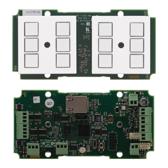
Defining the RC-76M/RC-712M Room Controllers Figure 1 defines the front panel of the RC-76M/RC-712M: Figure 1: RC-76M/RC-712M Room Controller – Front Panel Feature Function 6/12 Configurable Buttons Button function is programmed by the K-Config Configuration software Use to learn the IR commands from a machine’s remote... -
Page 9: Figure 2: Rc-76M/Rc-712M Room Controllers - Rear Panel
Figure 2 defines the rear panel of the RC-76M/RC-712M: Figure 2: RC-76M/RC-712M Room Controllers – Rear Panel Feature Function K-NET Terminal Block Connector Connect the GND pin to the Ground connection; pin B (-) and pin A (+) are for RS-485, and the... - Page 10 First, disconnect the power supply and then connect it again while pressing the Reset button. The unit powers up and loads its memory with the factory default definitions and erases all stored preset RELAY C2 Connect to low-voltage relay-driven device 2 RC-76M/ RC-712M - Overview...
-
Page 11: Installing The Rc-76M/Rc-712M
Attach the faceplates Configuring the Room Controller Buttons Configure the 6 buttons for RC-76M and 12 buttons for RC-712M using the K−Config configuration software via the USB port that is located on the front panel on the board or the Ethernet port located on the rear panel. Use the IR learning receiver on the front panel to read IR commands from any IR remote control. -
Page 12: Figure 3: Merten Compatible Housing
Although the illustration in Figure 4 shows the RC-712M, the following example applies also to the RC-76M. To connect the RC-76M/RC-712M as illustrated in the example in Figure 1. Connect the IR outputs as follows: Connect an IR emitter to IR OUTPUT 1 and attach the emitter to the DVD player 1 ... -
Page 13: Figure 4: Connecting The Rc-712M
4.2.1.1 Connecting RS-232 Devices You can control up to two AV devices such as a projector or an RS-232 display by connecting them to the RC-76M/RC-712M via their RS-232 connection. To connect a device to the RC-76M/RC-712M via RS-232: ... -
Page 14: Connecting The Ethernet Port
4.2.1.2 Connecting RS-485 Devices You can control up to one AV device by connecting it to the RC-76M/RC-712M via its RS-485 connection. To connect a device to the RC-76M/RC-712M via RS-485: Connect the A (+) pin of the device to the A pin on the RS-485 terminal block of the RC-76M/RC-712M ... -
Page 15: Connecting The K-Net Port
To mount the RC-76M/RC-712M: 1. Reconnect the detachable terminals to the rear panel 2. Gently place the RC-76M/RC-712M inside the housing, making sure that all cables remain connected. Figure 6: Inserting the RC-76M/RC-712M... -
Page 16: Figure 7: Securing The Rc-76M/Rc-712M
3. Secure the unit to the housing by screwing the four 3.5x10 conical Philips screws (supplied with the unit) into their 4 designated holes (see Figure Figure 7: Securing the RC-76M/RC-712M 4. Mount the frame over the device (see Figure Figure 8: Placing the Frame RC-76M/ RC-712M - Installing the RC-76M/RC-712M... -
Page 17: Figure 9: Button Cap Orientation With Label
Figure 10: Placing the Button Caps and Mounting the Device 7. Place the faceplates over the frame while fitting the buttons in (for the RC-76M you need to attach one button faceplate and one blank faceplate), Figure RC-76M/ RC-712M - Installing the RC-76M/RC-712M... -
Page 18: Figure 11: Placing The Faceplates
Note that if you need to reconfigure the buttons, simply remove these two screws and remove the frame and faceplate to gain access to the IR learner and USB port. Figure 12: Securing the Frame and Faceplates RC-76M/ RC-712M - Installing the RC-76M/RC-712M... -
Page 19: Operating The Rc-76M/Rc-712M
Operating the RC-76M/RC-712M You can operate your RC-76M/RC-712M via the front panel buttons or remotely by AUX. keypad over K-NET. The front panel buttons are configured using the K-Config software. For instructions on using the software, see the K-Config Software Guide available from... -
Page 20: Front Panel Button Labels
Front Panel Button Labels The RC-76M/RC-712M are supplied with a button label sheet and 6/8 clear, button caps to house the labels. Figure 13 illustrates a sample button label sheet. RC-76M/ RC-712M - Front Panel Button Labels... - Page 21 RC-76M/ RC-712M - Front Panel Button Labels...
-
Page 22: Figure 13: Sample Button Label Sheet
Figure 13: Sample Button Label Sheet RC-76M/ RC-712M - Front Panel Button Labels... -
Page 23: Technical Specifications
7.9cm x 2.8cm x 12.4cm (3.1" x 1.1” x 4.9") W, D, H DIMENSIONS: (with wall plate) WEIGHT: 0.245kg (0.54lbs) approx. ACCESSORIES: Power supply, button caps, button labels OPTIONS Merten-compatible 2 gang on-wall box (housing and frame, P/N: OWB-2G/M) Specifications are subject to change without notice RC-76M/ RC-712M - Technical Specifications... - Page 25 For the latest information on our products and a list of Kramer distributors, visit our Web site where updates to this user manual may be found. SAFETY WARNING Disconnect the unit from the power supply before opening and servicing P/N:...
Need help?
Do you have a question about the RC-712M and is the answer not in the manual?
Questions and answers