Table of Contents
Advertisement
Quick Links
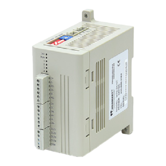
MTC-04-NTT Thermostat User Manual
Thank you for using Megmeet MTC-04-NTT module. Before using the
PLC product, please carefully read this booklet so as to better
understand it, fully use it, and ensure safety.This user manual is to offer
you a quick guide to the design, installation, connection and
maintenance of MTC-04-NTT module, convenient for on-site reference.
Briefly introduced in this booklet are the hardware specs, features, and
usage of MTC-04-NTT module, plus the optional parts and FAQ for
your reference.
This manual MTC-04-NTT module for the following members:
MTC-04-NTT Thermostat User Manual
Version
1.0
Revision date
July 16, 2012
BOM
1.Introduction
Model description as 1-1.
M TC 04
N
TT
-
-
Table 1-1 Module Description
2.Wiring Instructions
User input wiring terminals shown in figure 2-1.
Table 2-1 MTC-04-NTT enter the user terminal wiring diagram
Figure ① ~ ⑦ wiring must be noted that seven aspects:
Output Method
R: Relay Output
T: Transistor Output
Input method
N: No CT (Current test)
Input
The same input and
output
channels
of
channel number and
module number
Thermostat
Megmeet
①The thermocouple (thermal resistance) signal is recommended to be
accessed via a shielded cable (connection cable). Cables should be
kept away from power lines or other wires that may cause
electromagnetic interference. It is recommended to use cables less
than 100 meters in length (connecting cables). There is impedance in
the cable (connecting cable), which will introduce measurement error.
Characteristic adjustment can solve this problem. For specific operation,
please refer to
"MTC-04-NTT
thermostat user manual".
②Thermal resistance (type Pt100, JPt100, Cu100, Cu50)
required the three-wire connection.
③ If there is too much electrical interference, the shield wire
(thermocouple compensationcable shielding terminal, thermal
resistance of the connecting cable shielding terminal 485 linescreen)
should be connected to ground terminal PG.
④The thermostat grounding PG should be good grounding.
⑤24V power supply can use the main output of 24Vdc auxiliary power
supply module, you can also use the other to meet the
requirements of power.
⑥ 3.2 user basis having the output performance indicators to select
the appropriate power supply and solid state relays
⑦ 4 external input support source input and sink input, input voltage
range DC18V ~ DC28V.
3.Instructions
3.1 Power indicator
The power indicator of MTC-04-NTT is shown in figure 3-1.
Table 3-1 Power indicator
Project
24Vdc (-15% ~ 20%), the maximum allowable ripple
Power
voltage 5%, maximum power consumption 160mA.
3.2 Performance indicators
Table 3-2 Performance indicators
Project
K、J、E、N、T、R、S、B(Applicable
Thermocouple
type
to each channel)
Input signal
Pt100、Cu100、JPt100、Cu50、Ni120
Thermal
resistant type
(Applicable to each channel)
Power supply voltage circuit: 5V~24V;
The biggest power supply voltage
The output
circuit: 30V; Loop current: 0.3A/24Vdc;
gate open
Output
leakage current when open:<
transistor
method
0.1mA/30Vdc;Minimum load:5mA
(5Vdc~24Vdc)
Delay output
≤DC30V or ≤AC250V; Current≤2A
Input method
Support source input and sink input
Input port
Voltage range
DC18V~DC28V
Sampling period
100 milliseconds or 1 second (optional)
0.1~2seconds or 1~100
Control cycle
default value for 0.2s or 2s
ON/OFF control,Hand control,PID
Control method
control.Heating and cooling PID
control①
Type K
-100℃~1200℃(-148℉~2192℉)
Type J
-100℃~600℃(-148℉~1112℉)
Type E
-100℃~850℃(-148℉~1562℉)
Type N
-100℃~1200℃(-148℉~2192℉)
Nominal
Type T
-200℃~300℃(-328℉~572℉)
Type R
0℃~1600℃(32℉~2912℉)
Temperat
Type S
0℃~1600℃(32℉~2912℉)
ure Rang
Type B
400℃~1800℃(752℉~3272℉)
Pt100
-150℃~600℃(-238℉~1112℉)
e
JPt100
-150℃~500℃(-238℉~932℉)
Cu100
-30℃~120℃(-22℉~248℉)
Cu50
-30℃~120℃(-22℉~248℉)
Ni120
-80.0℃~280.0℃ (-112.0℉~536.0℉)
Instruction
Indicators
seconds,The
1
Advertisement
Table of Contents

Related Manuals for Megmeet MTC-04-NTT


Summary of Contents for Megmeet MTC-04-NTT
- Page 1 MTC-04-NTT module, convenient for on-site reference. required the three-wire connection. Briefly introduced in this booklet are the hardware specs, features, and usage of MTC-04-NTT module, plus the optional parts and FAQ for ③ If there is too much electrical interference, the shield wire your reference.
- Page 2 For more about the PID, set, alarm, MCbus and other related content and routines, please refer to the MTC-04-NTT thermostat user manual When the interference and b3:Set value ". the MTC due to an internal error...
- Page 3 ON/OFF 3:PID Default value:1 0:Cooling 3. 3.3 control function setting 1:Heating MTC-04-NTT buffer (BFM) set the control function of the content to 2:Heating and table 3-7. cooling (air #100 #100 #101...
- Page 4 Content Remarks Content Remarks CH1 CH2 CH3 CH4 CH1 CH2 CH3 CH4 proportional 100% Default value 0: band Setting connect channel adjusting range:0~1000% 1 alarm 1 mode factor 1: Turn off the output Heat side Default value: OUT 5 output 2: Turn on the #110 #111...
- Page 5 × value Significance Content Remarks (decimal) CH1 CH2 CH3 CH4 R-type thermocouple .Scope :32.0~ Default value 0: 2912.0℉ connect channel 1 alarm 1 mode S-type thermocouple .Scope :0.0~1600.0℃ 1: Turn off the S-type thermocouple .Scope :32.0~ output 2912.0℉ OUT 11 2: Turn on the Pt100.Scope :-50.0~150.0℃...
- Page 6 MTC-04-NTT fault. 3. 3.4 BFM parameters save Settings Check the state RUN indicator MTC-04-NTT buffer (BFM) of the BFM parameter set to save the High-speed flash: MTC-04-NTT is operating normally. contents of Table 3-9. Slow Flashing: Check BFM # 735, BFM # 736 in the information.
Need help?
Do you have a question about the MTC-04-NTT and is the answer not in the manual?
Questions and answers