Table of Contents
Advertisement
Quick Links
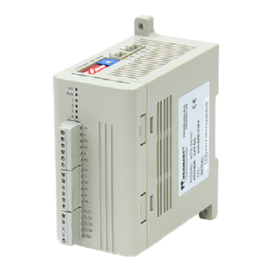
MTC-04-NVT Thermostat User Manual
Thank you for using Megmeet MTC-04-NVT module. Before using the
PLC product, please carefully read this booklet so as to better
understand it, fully use it, and ensure safety.This user manual is to offer
you a quick guide to the design, installation, connection and
maintenance of MTC-04-NVT module, convenient for on-site reference.
Briefly introduced in this booklet are the hardware specs, features, and
usage of MTC-04-NVT module, plus the optional parts and FAQ for
your reference.
This manual MTC-04-NVT module for the following members:
MTC-04-NVT Thermostat User Manual
Version
1.0
Revision date
June 16, 2012
BOM
1.Introduction
Model description as 1-1.
M TC 04
N
VT
-
-
Table 1-1 Module Description
2.Wiring Instructions
User input wiring terminals shown in figure 2-1.
Table 2-1 MTC-04-NVT enter the user terminal wiring diagram
Figure ① ~ ⑦ wiring must be noted that seven aspects:
VT:Analog
and
crystal
temperature
control,
4
transistor alarm, 4 I/O port
input
Input method
N: No CT (Current test)
Input
The same input and
output
channels
of
channel number and
module number
Thermostat
Megmeet
①The rmocouple (thermal resistance) signals suggested accessing by
shieded compensation cable. Cables away from power lines
or other wires may produce electromagnetic interference. It is
recommended to use less than 100 m compensation cable (connecting
cable) that be suscepted by noise interference Compensation cable
(cable) exist resistance, will introduce measurement error, adjustment
feature to resolve this issue, please refer to the specific
operation "MTC-04-NVT thermostat user manual."
②Thermal resistance (type Pt100, JPt100, Cu100, Cu50)
required the three-wire connection.
③ If there is too much electrical interference, the shield wire
(thermocouple compensationcable shielding terminal, thermal
resistance of the connecting cable shielding terminal 485 linescreen)
should be connected to ground terminal PG.
④ The thermostat grounding PG should be good grounding.
⑤24V power supply can use the main output of 24Vdc auxiliary power
supply module, you can also use the other to meet the
requirements of power.
⑥ 3.2 user basis having the output performance indicators to select
the appropriate power supply and solid state relays
⑦ Output control of analog quantity, there are four groups of analog
quantity (V1+/I1+/VI1-; V2 + / I2 + / VI2 -; V3 + / I3 + / VI3 -;
V4+/I4+/VI4-), select voltage control or current control output in each
group of analog quantities when temperature control. Current drive load
≤350Ω, voltage drive load≥2KΩ
⑧4 external input support source and sink input, input voltage range
DC18V ~ DC28V.
3.Instructions
3.1 Power indicator
The power indicator of MTC-04-NVT is shown in figure 3-1.
Table 3-1 Power indicator
Project
24Vdc (-15% ~ 20%), the maximum allowable ripple
Power
voltage 5%, maximum power consumption 160mA.
3.2 Performance indicators
Table 3-2 Performance indicators
Project
Thermocoupl
K、 J、 E、 N、 T、 R、 S、 B (Applicable to each channel)
e type
Input
Pt100、Cu100、JPt100、Cu50、Ni120(Applicable
signal
Thermal
resistant type
to each channel)
4~20mA,0~20mA;0~1V,0~5V,1~5V,0~10V(optional
Output
)①
method
Analog
Precision
0.5%
output
Current drivers load ≤350 Ω , voltage driving load
Specification
≥2KΩ
Power supply voltage circuit:5V~24V;The
biggest power supply voltage circuit:30V;Loop
The output
Output
gate open
current:0.3A/24Vdc;leakage current when open:
method
transistor
<0.1mA/30Vdc;Minimum load:5mA(5Vdc~
24Vdc)
Input method Support source input and sink input
Input
Voltage
port
DC18V~DC28V
range
Sampling period
100 milliseconds or 1 second (optional)
0.1~10 seconds or 1~100
Control cycle
value for 0.2s or 2s
ON/OFF control, Hand control, PID control.Heating
Control method
and cooling PID control②
Type K
-100℃~1200℃(-148℉~2192℉)
Nominal
Type J
-100℃~600℃(-148℉~1112℉)
Type E
Tempe
-100℃~850℃(-148℉~1562℉)
Type N
-100℃~1200℃(-148℉~2192℉)
rature
Type T
-200℃~300℃(-328℉~572℉)
Instruction
Indicators
seconds,The default
1
Advertisement
Table of Contents

Related Manuals for Megmeet MTC-04-NVT


Summary of Contents for Megmeet MTC-04-NVT
- Page 1 ②Thermal resistance (type Pt100, JPt100, Cu100, Cu50) Briefly introduced in this booklet are the hardware specs, features, and required the three-wire connection. usage of MTC-04-NVT module, plus the optional parts and FAQ for your reference. ③ If there is too much electrical interference, the shield wire...
- Page 2 4. BFM parameters save Settings; 5. Other. b1:Save - - For more about the PID, set, alarm, MCbus and other related content and routines, please refer to” the MTC-04-NVT thermostat user manual AD converter or other hardware Hardware ". b2:Hardware fault failure...
- Page 3 ON/OFF 3:PID Default value:1 0:Cool control 3. 3.3 control function setting 1:Heat control 2:Heat and cool MTC-04-NVT buffer (BFM) set the control function of the content to #100 #100 #101 #101 Heat/Cool (air cooling) table 3-7.
- Page 4 Natu Content Remarks Content Remarks CH1 CH2 CH3 CH4 CH1 CH2 CH3 CH4 method is Default value:0 effective) 0:Turn off External external manual / manual / automatic switch #121 #121 #121 #121 automatic input bumpless 1:Turn on Content Remarks switch setting external manual / CH1 CH2 CH3 CH4 * 13...
- Page 5 OUT3, OUT4 and OUT1 similar. Cu100,.Scope:-30.0~120.0℃ Cu100,.Scope:-22.0~248.0℉ 3. 3.4 BFM parameters save Settings Cu50,.Scope:-30.0~120.0℃ Cu50,.Scope:-22.0~248.0℉ MTC-04-NVT buffer (BFM) of the BFM parameter set to save the contents of Table 3-9. Ni120,.Scope:-80.0℃~280.0℃ Ni120,.Scope:-112.0℉~536.0℉ able 3-9 MTC-04-NVT buffer (BFM) BFM parameters save Settings PT100,.Scope::-150.0~300.0℃...
- Page 6 BFM with special operations area regulations required timing operation. 4. 2 Fault inspection If MTC-04-NVT run normally, please check the following projects. Check 24 V indicator state. Light: 24 Vdc power supply normal; Extinguish: 24 Vdc power supply may fault; If 24 Vdc power supply normal, the MTC-04-NVT fault.
Need help?
Do you have a question about the MTC-04-NVT and is the answer not in the manual?
Questions and answers