Advertisement
Quick Links
Advertisement

Related Manuals for Megmeet MTC-04-NVT


Summary of Contents for Megmeet MTC-04-NVT
- Page 1 MTC-04-NVT Thermostat User Manual Version V1.0 Archive time 2012.7...
- Page 2 Shenzhen megmeet control technology co., ltd. provides customers with a full range of technical support, users can contact with the nearest agents or technical service center of Shenzhen megmeet control technology co., ltd., or directly with the headquarters of the company.
- Page 3 Model Description TT:Analog voltage temperature M TC control, 4 transistor alarm, 4 I/O port input Input method N: No CT (Current test) Input The number of temperature channels collected by the module Thermostat Megmeet...
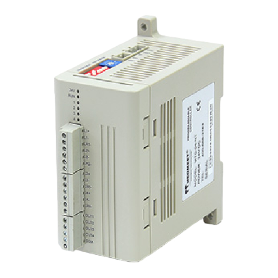
- Page 4 MTC-04-NVT. 1.1Appearance structure and installation dimensions The user terminal of the MTC-04-NVT thermostat is shown in figure 1-1 Figure 1-1 MTC-04-NVT outline structure diagram The mounting dimensions of MTC-04-NVT are shown in figure 1-2 Figure 1-2 MTC-04-NVT installation dimensions (unit: mm) 1.2 Terminal introduction...
- Page 5 MTC-04-NVT user terminal is shown in figure 1-3 Figure 1-3 MTC-04-NVT user terminal diagram The definition of MTC-04-NVT user terminal is shown in table 1-1 Table 1-1 MTC-04-NVT terminal definitions Mark Definition 24V- Power supply 24V positive 24V+ Power supply 24V negative Ground 485-...
- Page 6 Project Instruction 24Vdc (-15% ~ 20%), the maximum allowable ripple voltage Power 5%, maximum power consumption 160mA. 1.4.2 Performance indicators The performance indicators of MTC-04-NVT are shown in table 1-4 Table 1-4 Performance indicators Item Indicators Thermocouple type Input K、J、E、N、T、R、S、B...
- Page 7 Cu100, Cu50 JJG 229-1998 1.5 Buffer description MTC-04-NVT and the main module exchange information through the buffer (BFM), using Modbus or MCbus. The cache that reads and writes properties can use MODBUS or MCBUS instructions to write and read the contents of any cell in the BFM region. If the reserved cell is read, it will get a value of 0.
- Page 8 6. Litre/temperature limit setting. 7. Save and set BFM parameters. 8. The other. 1.5.1 Channel operation monitoring The channel operation monitoring content of the buffer zone (BFM) of MTC-04-NVT is shown in Table 1-5 Table 1-5 MTC-04-NVT buffer (BFM) channel operation monitoring natur...
- Page 9 Incomplete control in a stable state b8~b15 Save - - 1.5.2 Channel characteristics set MTC-04-NVT buffer (BFM) channel characteristics set as table1-8 Table 1-8 MTC-04-NVT buffer (BFM) channel characteristics set Natu Content Remarks CH1 CH2 CH3 CH4 #200 Restore factory setting*1...
- Page 10 ±100℉. If a value is set beyond this range, the MTC will not accept it and will keep the original valid setting. 1.5.3 control function setting MTC-04-NVT buffer (BFM) set the control function of the content to table1-9. Table 1-9 MTC-04-NVT buffer (BFM) the control function of the set Content...
- Page 11 Content Remarks Nature Save Cool side Default value:60 #973 #974 #975 #976 derivative Range:0~3600 (Seconds) time Default value:0 No overlapped non-inductive belt #981 #982 #983 #984 Overlap/Deadband*4 Setting range:-input range~+input range Undershoot Water-cooled default #989 #990 #991 #992 suppression Air-cooled default Range:0~1000 factor*5 Default value:B0000...
-
Page 12: Table Of Contents
Content Remarks Nature Save band adjusting factor Setting range:0~1000% Heat side integral Default value:100% #1109 #1110 #1111 #1112 time adjusting factor Setting range:0~1000% Heat side derivative Default value:100% #1117 #1118 #1119 #1120 time adjusting factor Setting range:0~1000% Cool side proportional Default value:100% #1125 #1126 #1127 #1128 band adjusting factor... -
Page 13: Value (Decimal)
value Significance (decimal) J-type thermocouple input range:-100.0~200.0℃ J-type thermocouple input range:-100.0~400.0℃ J-type thermocouple input range:-100.0~600.0℃ J-type thermocouple input range:-148.0~752.0℉ J-type thermocouple input range:-148.0~1112.0℉ E-type thermocouple input range:-100.0~200.0℃ E-type thermocouple input range:0.0~850.0℃ E-type thermocouple input range:-148.0~1562.0℉ N-type thermocouple input range:-100.0~1200.0℃ N-type thermocouple input range:-148.0~2192.0℉ T-type thermocouple input range:-200.0~200.0℃... - Page 14 Settings and external input are valid, the manual/automatic temperature control modes switch to each other. The external port inputs IN1 control channel 1, IN2 control channel 2, and so 1.5.4 Multi-step function setting The multi-step function Settings of mtc-04-nvt buffer (BFM) are shown in table 1-11...
- Page 15 Table 1-11 multi-step function Settings for the buffer (BFM) of mtc-04-NVT Content Remarks Nature Save Default value :0.0, #400 #419 #438 #457 Step 1 temperature * 1 denoted by 0.1℃ Default value :0.0, #401 #420 #439 #458 Step 2 temperature * 1 denoted by 0.1℃...
-
Page 16: Default Value:0
* 1. #600 ~ #603: alarm enable, from which the user can determine the type of alarm required to enable. #600 sets the alarm type 1, #601 sets the alarm type 2, and so on. Mtc-04-nvt offers 14 warning types, four of which can be selected simultaneously (see 5.3.1 warning types). - Page 17 1.6 Attachment List The terminal blocks supplied with the MTC-04-NVT terminals are shipped with the terminal. The details are shown in the table below. Table 1-15 List of accessories...
- Page 18 2.1.1 Installation location requirements As shown in figure 2-1, mtc-04-nvt shall be installed horizontally on the back panel of the electric cabinet, installed up and down and maintaining the air space above and below it. Other direction installation is not conducive to their own heat dissipation, for the improper installation.
- Page 19 Figure 2-2 Fixing with DIN slot The specific installation steps are as follows: 1. Fix the DIN groove horizontally on the mounting back plate; 2. Pull out the DIN slot clasp at the bottom of the module; 3. Attach the module to DIN; 4.
- Page 20 2.2.2 Wiring instructions User terminal input wiring is shown in Figure 2-4. Table 2-1 MTC-04-NVT enter the user terminal wiring diagram Figure ① ~ ⑦ wiring must be noted that seven aspects: ①The rmocouple (thermal resistance) signals suggested accessing by shieded compensation cable. Cables away from power lines or other wires may produce electromagnetic interference.
- Page 21 ⑧4 external input support source and sink input, input voltage range DC18V ~ DC28V. 2.2.3 Cable specifications When wiring for mtc-04-nvt applications, it is recommended to use multi-ply copper conductors and prefabricate insulated terminals to ensure the wiring quality. The cross-sectional area and model of the recommended conductor are shown in table 2-1.
- Page 22 The connection methods of communication lines are different in different system networking modes. 1.The temperature controller is connected to the main PLC module of MEGMEET. The user needs to use twisted pair to connect the RS485 communication terminal of MTC and the RS485 communication terminal of the main module (see the user manual of the relevant main module).
- Page 23 Modbus and MCbus. The former as a general communication protocol, widely support a variety of system configuration; The latter, as a communication protocol for MEGMEET, is specially used for internal communication of MEGMEET series PLC systems. This chapter introduces MTC communication and networking based on two communication protocols.
- Page 24 BFM address is 100, and the logical address of Modicon data is 4:101. 3.2 MCbus communication protocol MCbus communication protocol is a small PLC network protocol developed by MEGMEET. MTC USES MCbus communication protocol when matching with MEGMEET series PLC modules.
- Page 25 Figure 3-3 parameter setting of communication port 3. Click the corresponding MCbus setting button to enter the MCbus protocol setting interface. As shown in the following figure. Figure 3-4 MCbus protocol (1) select the baud rate and parity supported by MTC. Baud rate range supported by MTC: 2400, 4800, 9600, 19200.
- Page 26 Note: 1. After the user completes the configuration of MTC and runs the MTC on power by using the MTC wizard Settings, the user can use the man-machine interface of any PLC that supports MEGMEET to configure and monitor the parameters of MTC. Please refer to the relevant manual of man-machine interface for details.
- Page 27 This section through the "man-machine interface +PLC+MTC" this application system to explain the general use of MTC thermostat. Taking MEGMEET series PLC as an example, ModBus is used for communication between man-machine interface and PLC, and McBus is used for communication between PLC and MTC.
- Page 28 D7542 CH2 heating control output D7558 value D7543 CH3 heating control output D7559 Error status word value D7544 CH4 heating control output D7560 Set value range wrong value address D7545 D7561 Cold junction temperature D7546 D7562 D7547 D7563 Read common5 1.
- Page 29 the definition of D components and write command 6. Table 3-7 Settings represent communication special meaning D element D7500 D7501 D7502~7530 D7531 MTC module station Write content number to be read Table 3-7 D component definitions for write command 6 D elements Explanation D elements...
- Page 30 D7537 D7553 D7538 D7554 D7539 D7555 D7540 D7556 D7541 CH1 temperature setting D7557 CH1~CH4 start and stop D7542 CH2 temperature setting D7558 D7543 CH3 temperature setting D7559 D7544 CH4 temperature setting D7560 D7545 D7561 D7546 D7562 D7547 D7563 Write command 7 1.
- Page 31 time D7514 D7530 D7515 D7531 2. MTC thermostat return the frame with the MCbus communication buffer. Take MTC#1 region as an example: when D7532 and D7563 change to 7, the write is successful and up to 30 D elements can be written at a time.
- Page 32 Table 3-13 D component definitions for write command 8 D elements Explanation D elements Explanation D7500 D7516 D7501 D7517 D7502 CH1 cooling side proportional D7518 CH1 cooling side derivative band time D7503 CH2 cooling side proportional D7519 CH2 cooling side derivative band time D7504...
- Page 33 D7544 CH4 cooling side integral time D7560 D7545 D7561 D7546 D7562 D7547 D7563 3.2.6 command word routine The routines written by the user in accordance with the method described in 3.2.5 programming are shown below. The routines written for the methods described are shown below. This routine takes the communication between the main module and MTC#1 as an example and operates under the cooperation of the man-machine interface.
- Page 34 M0, M1, M2 through the man-machine interface through the PLC itself can be set. 4.MTC wizard settings The MTC wizard setting is a sub-function module of MEGMEET programming software X_Builder, which is started by X_Builder. Its main function is to configure MTC parameters after MTC network with MCbus protocol, monitor MTC status and data at the same time.
- Page 35 Figure 4-1 MTC wizard Settings Configuration module The software default system is configured with a station number of 1 MTC thermostat. In actual use, the user should configure the module according to the actual configuration of MTC. 1. When a single MTC is configured on the system. At this point, the user only needs to modify the module type.
- Page 36 tree on the left side of the interface. (4)In the shortcut menu that pops up, select add module and enter the following interface. Figure 4-3 Add module (5) Repeat steps 2 ~ 3 according to the actual number of MTC configured, until all MTC are assigned the corresponding station number.
- Page 37 Figure 4-4 save the module configuration information 4.2.3 restore factory Settings To restore factory Settings, the user shall: 1) select save setting page in the MTC wizard setting interface. As shown in the following figure. Figure 4-5 save the Settings page 2) click the restore BFM factory Settings button.
- Page 38 When the relevant PLC system is in operation state, and the PC is connected to the PLC main module by programming cable, the user can monitor the thermostat in real time through the monitoring function set by the MTC wizard. The relevant operation methods are shown in the following table. Table 4-1 monitoring methods Operation type Method of operation...
- Page 39 5.Feature setting and function description This chapter introduces the channel characteristics of MTC and various functions of MTC in detail. 5.1 Feature settings The input channel characteristic of MTC is the linear relationship between the channel analog input temperature A and the channel digital output D, which can be set by the user. Each channel can be understood as the model shown in Figure 5-1.
- Page 40 D0 and D1 values below. If you change the D0 and D1 values of the channel, you can change the channel characteristics. D0 and D1 are allowed to be adjusted ± 1000 on the basis of factory settings. If the current mode uses Celsius, the adjustment range is ± 100.0 ° C. If the current mode uses Fahrenheit, the adjustment range is ±...
- Page 41 5.2.3 requires PID control PID control is through setting each constant P (proportional coefficient) I (integral time) D (differential time) can obtain the stable control effect. Set the MTC control mode setting unit (BFM#1000 ~ BFM#1003) as 2 to make the corresponding channel work in the PID control mode, then set the PID parameters, and then in the control start/stop setting unit (BFM#997) the corresponding channel position will be written 1, at this time the corresponding channel of MTC will start PID control according to the parameters set.
- Page 42 No alarm No alarm Turn off the alarm function Alarm when the measured value (PV) is High limit Input scope larger than the alarm setting Alarm when the measured value (PV) is Low limit Input scope smaller than the alarm setting Alarm when the deviation value (measure Deviation high value-setting value) is larger than the...
- Page 43 Alarm when the deviation (measured Wait again with value-set value) is greater than the alarm the deviation low set value, but the measured value will be ± input width limit alarm ignored when the power is turned on and the set value changes When the absolute value of deviation (| Wait again with measured value - set value |) is larger...
- Page 44 Figure 5-8 Schematic diagram of the deviation high(The deviation is positive) Figure 5-9 Schematic diagram of the (The deviation is negative) deviation high 4.Deviation low Alarm when the deviation value (= PV - SV) is smaller than the alarm setting value Figure 5-10 Schematic diagram of the deviation low(The deviation is positive)...
- Page 45 Figure 5-12 Schematic diagram of the deviation high/low 6. Band Alarm when the absolute value of deviation (= | PV - SV |) is smaller than the alarm setting value Figure 5-13 Schematic diagram of the band Alarm, Waiting for the alarm and Wait for the second alarm 1....
- Page 46 diagram Figure 5-15 Schematic of the lower limit of wait with the deviation low alarm 3. Waiting for the alarm again is to wait one more time on the basis of waiting for the alarm, that is, ignore the alarm triggered by the measured value when the power is connected (waiting) and the alarm triggered by the measured value when the set value is changed (waiting), until the measured value next triggers the alarm, as shown in figure 5-16.
- Page 47 Figure 5-18 Schematic diagram of low limit deviation low Figure 5-19 Schematic diagram of deviation high/low 5.3.3 Alarm delay When the deviation between the measured value PV and the set value SV reaches the alarm setting value, the alarm delay function will remain in the non-alarm state. No warning will be given until the number of input samples exceeds the number of alarm delay.
- Page 48 5.5 PID control function of heating and cooling MTC-04-NVT when the input type of channel 2 and channel 4 is selected as 0, the temperature control output OUT2 and OUT4 will be automatically assigned to the refrigeration control output of channel 1 and channel 3.
- Page 49 6. Application examples The MTC wizard Settings can help users set some parameters. However, the function that needs to make logical judgment needs to be realized through programming on the basis of completing the corresponding parameter setting. This chapter introduces the MTC parameter configuration through the MTC wizard setting and programming method respectively.
- Page 50 Figure 6-2 Modify module parameters 4. Select the control function and select "3", "9", "27" and "37" in the input type selection, as shown in the following figure. Figure 6-3 Input type selection 5. Select the channel characteristics and input the following contents in D0 and D1 respectively. Note that the unit is 0.1℃/℉.
- Page 51 Figure 6-4 Input D0,D1 6.Right-click the site 2 option under the module configuration in the left tree structure, and select download from the right-click menu that pops up. Figure 6-5 Download 7.The feature change is completed when the download site 2 configuration is completed in the lower left corner of the interface.
- Page 52 1. Refer to the 6.1 feature to change the first three steps for setting. 2. Select the control function and set it according to the figure below. Figure 6-7 setting control function 3.Select the alarm function and set it as shown in the figure below. Figure 6-8 setting alarm function 4.Right-click the site 2 option under the module configuration in the left tree structure, and select...
- Page 53 download from the right-click menu to complete the setup. 6.3 the setting Example: MTC station number is 2. Set the first channel to use mode 3, work in the heating mode, the given value is 100.0℃, the control cycle is 3 seconds, use the self-tuning mode, the self-tuning deviation is set to -20℃.
- Page 54 set values and time of 1 ~ 4 segments of multiple segments. Table 6-1 set values and time number of segments Setting 100.0 150.0 200.0 250.0 200.0 150.0 100.0 100.0 value(℃) Time(s) The beginning section of repetition is 3, the end section of repetition is 6, and the number of repeats is 3. 1.
- Page 55 3. Right click the option of site 2 under the module configuration in the left tree structure, and select download to complete the setup from the right click menu. 7.Operation check This chapter introduces the routine and fault checking methods of MTCW. 7.1 Routine check 1.
- Page 56 tuning start 7th channel auto M1406 M1414 M1422 M1430 M1438 M1446 M1454 tuning start 8th channel auto M1407 M1415 M1423 M1431 M1439 M1447 M1455 tuning start M1456~M1462 Meaningless Alarm 1 status of M1464 M1528 M1592 M1656 M1720 M1784 M1848 channel 1 Alarm 2 status of M1465 M1529...
- Page 57 Alarm 3 status of M1482 M1546 M1610 M1674 M17387 M1802 M1866 channel 3 Alarm 4 status of M1483 M1547 M1611 M1675 M1739 M1803 M1867 channel 3 Initialization M1484 M1548 M1612 M1676 M1740 M1804 M1868 complete flag of channel 3 Auto-tuning state of M1485 M1549 M1613...
- Page 58 M1509 M1573 M1637 M1701 M1765 M1829 M1893 M1510 M1574 M1638 M1702 M1766 M1830 M1894 M1511 M1575 M1639 M1703 M1767 M1831 M1895 M1512 M1576 M1640 M1704 M1768 M1832 M1896 M1513 M1577 M1641 M1705 M1769 M1833 M1897 M1514 M1578 M1642 M1706 M1770 M1834 M1898 M1515...
Need help?
Do you have a question about the MTC-04-NVT and is the answer not in the manual?
Questions and answers