Table of Contents
Advertisement
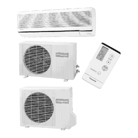
CS-A73KR/CU-A73KR / CS-A93KR/CU-A93KR / CS-A123KR/
2000 Matsushita Air-Conditioning Corp. Sdn. Bhd. (183914D) All
rights reserved. Unauthorized copying and distribution is a
violation of law.
1. Features
- High Efficiency
- Compact Design
- Comfort Environment
Order No: MAC0001007C3
Room Air Conditioner
1
CU-A123KR
Advertisement
Table of Contents
Troubleshooting

Related Manuals for Panasonic CS-A73KR


Summary of Contents for Panasonic CS-A73KR
- Page 1 Order No: MAC0001007C3 Room Air Conditioner CS-A73KR/CU-A73KR / CS-A93KR/CU-A93KR / CS-A123KR/ CU-A123KR 2000 Matsushita Air-Conditioning Corp. Sdn. Bhd. (183914D) All rights reserved. Unauthorized copying and distribution is a violation of law. 1. Features - High Efficiency - Compact Design - Comfort Environment...
- Page 2 - 8 hours of sleep mode operation - Air purifying filter with deodorizing function to reduce dust, smoke and odours - Random Auto Restart - Auto restart at randomly after power failure - Removable and Washable Front Panel - Quality Improvement - Gas leakage protection - Prevent compressor reverse rotation - 2-stage OLP to protect compressor...
- Page 3 Unit CS-A73KR CU-A73KR Cooling Capacity 2.11 - 2.06 Btu/h 7,200 - 7,020 Heating Capacity 2.30 - 2.25 Btu/h 7,840 - 7,670 Moisture Removal Pint/h Power Source Phase Single 240 - 220 Cycle Airflow Method OUTLET SIDE VIEW TOP VIEW INTAKE...
- Page 4 Air Volume Indoor Air (Lo) Cooling; 5.9 (206) - 5.5 — /min (194) (cfm) Heating; 7.4 (261) - 6.4 (226) Indoor Air (Me) Cooling; 6.9 (244) - 6.3 — /min (222) (cfm) Heating; 8.0 (282) - 7.4 (261) Indoor Air (Hi) Cooling;...
- Page 5 Electrical Data Input Cooling; 660 - 610 Heating; 640 - 580 Running Current Cooling; 3.2 - 3.0 Heating; 3.0 - 2.8 COP/EER Cooling; 3.20 - 3.38 Heating; 3.59 - 3.88 Starting Current 11.2 Piping Connection Port inch G ; Half Union 3/8” G ;...
-
Page 6: Specifications Are Subject To Change Without Notice For Further Improvement
Refrigeration Oil (c.c) — SUNISO 4GDID ATMOS M60 Refrigerant (R-22) g (oz) — 860 (30.4) Thermostat Electronic Control — Protection Device — Overload Protector Capillary Tube Length — Cooling; 920, Flow Rate l/min — Cooling; 4.0, Heating Inner Diameter — Cooling;... - Page 7 Air Volume Indoor Air (Lo) Cooling; 6.5 (229) - 6.1 — /min (215) (cfm) Heating; 6.8 (240) - 6.7 (237) Indoor Air (Me) Cooling; 7.8 (275) - 7.4 — /min (261) (cfm) Heating; 8.2 (289) - 8.1 (286) Indoor Air (Hi) Cooling;...
- Page 8 Electrical Data Input Cooling; 970 - 920 Heating; 910 - 840 Running Current Cooling; 4.3 - 4.3 Heating; 4.0 - 3.9 COP/EER Cooling; 2.73 - 2.83 Heating; 3.52 - 3.69 Starting Current 17.1 Piping Connection Port inch G ; Half Union 3/8” G ;...
- Page 9 Refrigeration Oil (c.c) — SUNISO 4GDID ATMOS M60 Refrigerant (R-22) g (oz) — 850 (30.0) Thermostat Electronic Control — Protection Device — Overload Protector Capillary Tube Length — Cooling; 1,075, Flow Rate l/min — Cooling; 5.0, 13.4 Inner Diameter — Cooling;...
- Page 10 Air Volume Indoor Air (Lo) Cooling; 7.6 (268) - 6.8 — /min (240) (cfm) Heating; 8.0 (281) - 7.4 (261) Indoor Air (Me) Cooling; 8.2 (289) - 7.7 — /min (272) (cfm) Heating; 8.6 (303) - 8.2 (289) Indoor Air (Hi) Cooling;...
- Page 11 Electrical Data Input Cooling; 1.31 - 1.26 Heating; 1.24 - 1.19 Running Current Cooling; 5.4 - 5.6 Heating; 5.0 - 5.2 COP/EER Cooling; 2.60 - 2.70 Heating; 3.35 - 3.40 Starting Current Piping Connection Port inch G ; Half Union 1/2” G ;...
- Page 12 Refrigeration Oil (c.c) — SUNISO 4GDID ATMOS M60 Refrigerant (R-22) g (oz) — 990 (34.9) Thermostat Electronic Control — Protection Device — Overload Protector Capillary Tube Length — Cooling; 1,100, Flow Rate l/min — Cooling; 6.0, 13.4 Inner Diameter — Cooling;...
-
Page 14: Refrigeration Cycle Diagram
5. Refrigeration Cycle Diagram... -
Page 15: Block Diagram
6. Block Diagram... -
Page 16: Wiring Diagram
7. Wiring Diagram... - Page 17 REMARKS : BLUE : BROWN : BLACK : WHITE : RED : ORANGE : PINK : YELLOW/GREEN...
-
Page 18: Operation Details
Resistance of Indoor Fan Motor Windings MODEL CS-A73KR CS-A93KR A123KR CONNECTION CWA92288 CWA92296 CWA92290 YELLOW-BLUE 536.5 450.8 457.4 YELLOW-BROWN 77.1 56.9 56.1 BROWN-ORANGE 43.9 74.2 61.2 ORANGE-WHITE 42.7 37.3 25.3 WHITE-RED 111.4 122.6 142.5 Resistance of Outdoor Fan Motor Windings... - Page 19 - When the setting temperature is reached during cooling operation, the compressor stops and it will not start for 3 minutes. 7 minutes Time Saved Control - The compressor will start automatically if it has stopped for 7 minutes even if the room temperature is between the compressor ON temperature and OFF temperature.
- Page 20 - If the compressor is operating continuously for 5 minutes or longer and the temperature difference between intake air and indoor heat exchanger is 2.5°C or less for 2 minutes, compressor will stop and restart automatically. / (Time Delay Safety Control is valid) T = Intake air temperature - Indoor heat exchanger temperature / This is to protect reverse rotation of the compressor when there is a instantaneous power failure.
- Page 21 Cooling Operation Time Diagram 8.2. Soft Dry Mode Operation - The unit starts cooling operation until the room temperature reaches the setting temperature set on the Remote Control, and...
- Page 22 then Soft Dry operation will start. - During Soft Dry operation, the Indoor Fan will operate and stop at 4- second intervals at low speed. - The operation will be switched on and off for up to 10 minutes “ON” and 6 minutes “OFF”. Once Soft Dry operation is turned off, it stops for 6 minutes.
- Page 23 Automatic Fan Speed Mode When Automatic Fan Speed is selected at Remote Control during Soft Dry operation. - Fan speed rotates at SLo and Lo speed. - Deodorizing Control. Soft Dry Operation Time Diagram...
- Page 24 8.3. Heating Mode Operation Heating in operation according to Remote Control setting. Time Delay Safety Control - When the compressor is stopped by Power Switch or Remote Control, it restarts after 3 minutes when the Power Switch or Remote Control is turned ON. - When the setting temperature is reached during heating operation, the compressor stops and it will not start for 4 minutes.
- Page 25 30 minutes Time Saved Control - The compressor will start automatically if it has stopped for 30 minutes even if the room temperature is below the compressor ON temperature. Overload Protection Control - If the temperature of the indoor heat exchanger rises to 51°C, Outdoor Fan stops.
- Page 26 - If the compressor is operating continuously for 5 minutes or longer and temperature difference between intake air and indoor heat exchanger is 5°C or less for 2 minutes, compressor will stop and restart automatically. (Time Delay Safety Control is valid). T = Indoor heat exchanger temperature - intake air temperature.
- Page 27 - When compressor stops (reaches room temperature), outdoor fan will operate for 30 seconds. (30 seconds Forced Operation). Hot Start Control When Heating operation starts, Indoor Fan will not start until the indoor heat exchanger reaches 30°C as diagram shown. Hot Start is completed when indoor heat exchanger reaches 39°C.
- Page 28 Note: SSLo: Fan will be running at Lo speed with Indoor heat exchanger temperature 1.5 sec ON and 5.5 sec OFF. - After 30 sec. from compressor OFF (thermo OFF), Indoor fan will run at SSLo speed only. - Anti Cold Draft Control will stop when: - Intake temperature <...
- Page 30 - If use Manual Fan Speed, at above diagram will operate with setting Fan Speed. Heating Operating Time Diagram Deicing Control Deice starts to prevent frosting at outdoor heat exchanger. - Normal Deicing Deice operations detection commences after 30 minutes of Heating operation starts or 60 minutes after previous deice operation.
- Page 31 (There is no detection during Outdoor Fan stops.) - Overload Deicing During heating operation, if the outdoor Fan OFF duration (due to overload control) is accumulated up to 60 minutes and after compressor starts for 1 minutes, deicing starts. - Deicing ends when 1.
- Page 32 Overload Deicing Time Diagram...
- Page 33 8.4. Automatic Mode Operation 1. When the Automatic Mode Operation is selected, the indoor fan operates at Lo fan speed for 20 second to sense intake air temperature and determine the 1st operation mode. 2. Operation mode will be determine again after 1 hour of operation, if the room temperature reaches to set temperature and compressor off time is over 7 minutes 30 seconds continuously.
- Page 34 Present Judgement Next Mode Mode Cooling Soft Dry Heating Cooling 23°C Cooling (Judgement: Not Applicable (Judgement 23°C & Above) Below 23°C) Heating Soft Dry 20°C Soft Not Applicable (Judgement: (Judgement 20°C & Above) Below 20°C) Heating Heating (Judgement: Not Applicable (Judgement Cooling 25°C Heating...
- Page 35 When you press the SLEEP Mode, the following movement will start to avoid overcooling. - The fan speed refer to Indoor Fan Motor Control. - The setting temperature will be risen by 0.5°C at the start of operation and by 0.5°C one hour later. - The operation will stop after 8 hours.
- Page 36 - This control can be omitted by open the circuit of JX1. (Refer Circuit Diagram) 8.7. Delay ON Timer Control - When the Delayed ON Timer is set by using the remote control, the unit will start operate slightly before the set time, so that the room will reach nearly to the set temperature by the desired time.
- Page 37 Manual Fan Speed Control Basic fan speed adjustment (3 settings, from Lo to Hi) can be carried out by using the Fan Speed selection button at the remote control. Stop Manual Normal Auto Fan Speed Sleep Shift COOLING Manual Powerful Auto Fan Speed Sleep Shift Manual...
- Page 38 Sleep Shift Manual Economy Auto Fan Speed Sleep Shift MODE JUDGEMENT 8.10. Airflow Direction Control 1. Vertical Airflow Direction Cooling and Soft Dry Mode - The louver swings up and down as shown above. - The louver does not swing when the Indoor Fan stops during operation.
- Page 39 from upper to lower limit. When the intake air temp falls to 35°C, the louver is changed from lower to upper limit. - The louver can be selected between 0° - 36° (as shown above) when pressing Manual Airflow Direction Selection Button. - The louver can be selected between 0°...
- Page 40 - Vertical Airflow Direction:- In “Manual” or “Auto” setting, the vane will automatically change to Auto Air Swing. 2. Heating Mode - When the Economy Mode is set, the temperature will be automatically decreased 0.5°C against the present setting temperature. - The Fan Speed will shift as shown below: - Vertical Airflow Direction:- In “Manual”...
- Page 41 under Super High Fan speed. - Vertical Airflow Direction:- In “Manual” setting, the vane will automatically shift down 10°C lower than previous setting. In “Auto” setting, the vane will automatically swing up and down. However the upper and down. However the upper and lower limit will be shifted 10°...
-
Page 42: Installation Instructions
9. Operating Instructions 10. Installation Instructions Required tools for Installation Works 1. Phillips screw 5. Spanner 9. Gas leak detector 13. Multimeter driver 2. Level gauge 6. Pipe cutter 10. Measuring tape 14. Torque wrench 18 N.m (1.8 kgf.m) 42 N.m (4.2 kgf.m) 3. - Page 43 - Carry out test running to confirm that no abnormality occurs after the installation. Then, explain to user the operation, care and maintenance as stated in instruction. Please remind the customer to keep the operating instructions for future reference. 1. Engage dealer or specialist for installation. If installation done by the user is defective, it will cause water leakage, electrical shock or fire.
- Page 44 1. Grounding is necessary. It may cause electrical shock if grounding is not perfect. 2. Do not install the unit at place where leakage of flammable gas may occur. In case gas leaks and accumulates at surrounding of the unit, it may cause fire. 3.
-
Page 45: Select The Best Location
Accessories: Flaring piping kit CZ-3F5, 7AEN SELECT THE BEST LOCATION INDOOR UNIT - There should not be any heat source or steam near the unit. - There should not be any obstacles blocking the air circulation. - A place where air circulation in the room is good. - A place where drainage can be easily done. -
Page 46: Indoor Unit
- This illustration is for explanation purposes only. / The indoor unit will actually face a different way. 10.2. INDOOR UNIT... -
Page 47: How To Fix Installation Plate
10.2.1. SELECT THE BEST LOCATION / (Refer to “Select the best location” section) 10.2.2. HOW TO FIX INSTALLATION PLATE The mounting wall is strong and solid enough to prevent it from the vibration. : Unit centre point should be at more than 450 mm at right and left of the wall. -
Page 48: Indoor Unit Installation
extended line is the centre of the hole. - Drill the piping hole at either the right or the left and the hole should be slightly slanted to the outdoor side. 10.2.3. TO DRILL A HOLE IN THE WALL AND INSTALL A SLEEVE OF PIPING 1. - Page 49 3. For the embedded piping...
- Page 50 (This can be used for left rear piping and left bottom piping also.)
-
Page 51: Connect The Cable To The Indoor Unit
10.2.5. CONNECT THE CABLE TO THE INDOOR UNIT 1. The inside and outside connecting cable can be connected without removing the front grille. 2. Connecting cable between indoor unit and outdoor unit shall be approved polychloroprene sheathed 3 × 1.5 mm flexible cord, type designation H05 RN-F or heavier cord. - Page 52 - Ensure the color of wires of outdoor unit and the terminal Nos. are the same to the Indoor’s respectively. - Earth lead wire shall be longer than the other lead wires as shown in the figure for the electrical safety in case of the slipping out of the cord from the anchorage.
-
Page 53: Install The Outdoor Unit
10.3. OUTDOOR UNIT 10.3.1. SELECT THE BEST LOCATION / (Refer to “Select the best location” section) 10.3.2. INSTALL THE OUTDOOR UNIT - After selecting the best location, start installation according to Indoor/outdoor Unit Installation Diagram. 1. Fix the unit on concrete or rigid frame firmly and horizontally by bolt nut. -
Page 54: Cutting And Flaring The Piping
as stated in the table. Connecting the Piping to Outdoor Unit Decide piping length and then cut by using pipe cutter. Remove burrs from cut edge. Make flare after inserting the flare nut (located at valves) onto the copper pipe. Align center of piping to valves and then tighten with torque wrench to the specified torque as stated in the table. -
Page 55: Connect The Cable To The Outdoor Unit
- Be sure to connect the end of the charging hose with the push pin to the service port. 2. Connect the center hose of the charging set to a vacuum pump. 3. Turn on the power switch of the vacuum pump and make sure that the needle in the gauge moves from 0 cmHg (0 MPa) to -76 cmHg (-0.1 MPa). -
Page 56: Pipe Insulation
2. Connecting cable between indoor unit and outdoor unit shall be approved polychloroprene sheathed 3 × 1.5 mm flexible cord, type designation H05 RN-F or heavier cord. 3. Secure the cable onto the control board with the holder (clamper). 4. Attach the control board cover back to the original position with the screw. -
Page 57: Way, 3-Way Valve
- Operate the unit at cooling operation mode for fifteen minutes or more. - Measure the temperature of the intake and discharge air. - Ensure the difference between the intake temperature and the discharge is more than 8°C. CHECK ITEMS Is there any gas leakage at flare nut connections? Has the heat insulation been carried out at flare nut / connection? - Page 58 2-way Valve (Liquid Side) 3-way Valve (Gas Side) Works Shaft Position Shaft Position Service Shipping Close Closed Closed (With valve cap) (With valve cap) (With Evacuation Closed Closed Open (Installation and (Counter-Clockwise) (Clockwise) (Push Re-installation) Operation Open Open Closed (With valve cap) (With valve cap) (With Pumping down...
- Page 59 2-way Valve (Liquid Side) 3-way Valve (Gas Side) Gas releasing Open (Servicing) Open Open (Connected manifold 11.1. Evacuation of Installation WHEN INSTALLING AN AIR CONDITIONER, BE SURE TO EVACUATE THE AIR INSIDE THE INDOOR UNIT AND PIPES in the following procedure. If air remain in the indoor unit and refrigeration pipes, it will affect the compressor, reduce to cooling capacity, and could lead to a malfunction.
- Page 60 4. Close the Low side valve of the charging set and turn off the vacuum pump. Make sure that the needle in the gauge does not move after approximately five minutes. BE SURE TO TAKE THIS PROCEDURE IN ORDER TO AVOID GAS LEAKAGE.
- Page 61 Procedure: Confirm that both the 2-way and 3-way valves are set to the opened position. - Remove the valve stem caps and confirm that the valve stems are in the opened position. - Be sure to use a hexagonal wrench to operate the valve stems.
- Page 62 P.C.B. (Simply press the pumping down button if it is equipped.) So that the unit can be operated. 7. Immediately set the 3-way valve to the closed position. - Do this quickly so that the gauge ends up indicating 0.1 MPa (1 kg/cm G) to 0.3 MPa (3 kg/cm 8.
- Page 63 Procedure: 1. Connect a charging hose with a push pin to the Low side of a charging set and the service port of the 3-way valve. - Be sure to connect the end of the charging hose with the push pin to the service port. 2.
- Page 64 Caution If gauge needle does not move from 0 MPA (0 cmHg) to -0.1 MPa (-76 cmHg) in step (3) above, take the following measures: If the leaks stop when the piping connections are tightened further, continue working from step 3. If the leaks do not stop when the connections are retightened, repair the location of the leak.
- Page 65 4. Open the valve (Low side) on the charge set and discharge the refrigerant until the gauge indicates 0.05 MPa (0.5 kg/cm G) to 0.1 MPa (1 kg/cm - If there is no air in the refrigeration cycle (the pressure when the air conditioner is not running is higher than 0.1 MPa (1 kg/ cm2G), discharge the refrigerant until the gauge indicates 0.05 MPa (0.5 km/cm2G) to 0.1 MPa (1 kg/cm2G).
- Page 66 (approximately 5 minutes after turning off the vacuum pump). 4. Disconnect the charge hose from the vacuum pump. - Vacuum pump oil If the vacuum pump oil becomes dirty or depleted, replenish as needed. 11.6. Gas charging (After Evacuation) Procedure: 1.
-
Page 67: Servicing Information
(approximately 150 g each time) while operating the air conditioner in the cooling cycle; however, one time is not sufficient, wait approximately 1 minute and then repeat the procedure. (pumping down-pin) This is different from previous procedures. Because you are charging with liquid refrigerant from the gas side, absolutely do no attempt to charge with large amount of liquid refrigerant while operating the air conditioner. - Page 68 - Releasing CN-C (GRN) connector. (Fig. 2) - Releasing CN-FM (GRN) connector. (Fig. 2) - Releasing CN-STM connector. (Fig. 2) - Remove the earth wire screw. (Fig. 2) - Release the intake air sensor. (Fig. 2) - Release the piping sensor. (Fig. 2) - Unhook and release the terminal board.
- Page 69 - Finally remove the fan motor by removing the screw. (Fig. 5) - REMINDER - To reinstall the fan motor, adjust the connector of the fan motor as Figure 5. - Cross Flow Fan Removal Procedure. 1. Remove the control board and the fan motor by referring to the “Indoor Fan Motor Removal Procedure”.
- Page 70 - Remote Control Reset When the batteries are inserted for the first time, or the batteries are replaced, all the indications will blink and the remote control might not work. If this happen, remove the back cover of the remote control and you will find a resetting terminal, and by shorting it with a minus...
-
Page 71: Troubleshooting Guide
screwdriver, it will return to normal. - Changing the wireless remote control transmission code When two indoor units are installed in the same room, in order to prevent operating errors caused by using two remote controls, set up the remote control [B A] switch (SW1). - Page 72 13.1. Refrigeration cycle system In order to diagnose malfunctions, make sure that there are no electrical problems before inspecting the refrigeration cycle. Such problems include insufficient insulation, problem with the power source, malfunction of a compressor and a fan. The normal outlet air temperature and pressure of the refrigeration cycle depends on various conditions, the standard values for them are shown in the table to the right.
- Page 73 Cooling Mode Heating Mode Condition of the conditoner Low Pressure High Electric Low Pressure High Electric Pressure current Pressure current during during operation operation Insufficient refrigerant (gas leakage) Clogged capillary tube or Strainer Short circuit in the indoor unit Heat radiation deficiency of the outdoor unit Inefficient...
-
Page 74: Technical Data
Nature of fault Symptom Electric current during operation becomes approximately 20% lower than the normal value. Insufficient compressing of a The discharge tube of the compressor becomes abnormally hot (normally 70 to 90°C). compressor The difference between high pressure and low pressure becomes almost zero. Electric current reaches a high level abnormally, and the value exceeds the limit of an ammeter. - Page 76 240V Outdoor Temp. (°C) Indoor Wet Bulb Temp. 17.0°C 2.07 1.88 0.61 1.94 1.81 0.65 1.81 1.69 0.70 1.65 1.46 0.75 19.0°C 2.11 0.66 19.5°C 2.30 1.65 0.61 2.15 1.54 0.66 2.00 1.52 0.71 1.84 1.46 0.76 22.0°C 2.55 1.54 0.62 2.38 1.35...
- Page 77 240V Outdoor Temp. (°C) Indoor Wet Bulb Temp. 17.0°C 3.33 3.03 1.21 3.13 2.92 1.30 2.92 2.72 1.39 2.65 2.35 1.49 19.0°C 3.40 1.31 19.5°C 3.71 2.65 1.22 3.47 2.48 1.31 3.23 2.45 1.40 2.96 2.35 1.51 22.0°C 4.11 2.48 1.23 3.84 2.18...
-
Page 80: Exploded View
15. Exploded View... -
Page 81: Replacement Parts List
Note: The above exploded view is for the purpose of parts disassembly and replacement. The non-numbered parts are not kept as standard service parts. 16. Replacement Parts List <Model: CS-A73KR / CS-A93KR / CS-A123KR>... - Page 82 DESCRIPTION & NAME Q’TY CS-A73KR CS-A93KR CS-A123KR REMARKS CHASSY COMPLETE CWD50C338 PARTICULAR PIECE CWD931019 FAN MOTOR CWA92288 CWA92296 CWA92290 LEAD WIRE - FAN MOTOR CWA67C2097 CROSS FLOW FAN CWH02C060 BEARING CWH64K007 SCREW - CROSS FLOW FAN CWH4580304 EVAPORATOR & TUBE ASS’Y COMPLETE...
- Page 83 DESCRIPTION & NAME Q’TY CS-A73KR CS-A93KR CS-A123KR REMARKS INSTALLATION PLATE CWH36157 BAG COMPLETE - INSTALLATION SCREW CWH82C194 AIR PURIFYING FILTER COMPLETE CWD00C111 AIR PURIFYING FILTER CWD00220 REMOTE CONTROL HOLDER CWH36161 (Note) - All parts are supplied from MACC, Malaysia (Vendor Code: 086).
- Page 84 Note: The above exploded view is for the purpose of parts disassembly and replacement. The non-numbered parts are not kept as standard service parts. 18. Replacement Parts List <Model: CU-A73KR / CU-A93KR>...
- Page 85 DESCRIPTION & NAME Q’TY CU-A73KR CU-A93KR REMARKS CHASSY ASS’Y CWD50K438F CWD50K456D FAN MOTOR BRACKET CWD54113 SCREW - FAN MOTOR BRACKET CWH4580399 FAN MOTOR CWA95245 SCREW - FAN MOTOR MOUNT CWH55027 PROPELLER FAN CWH00K052 NUT - PROPELLER FAN CWH56032 COMPRESSOR 2RS122D5AB02 2PS164D3AD02 ANTI - VIBRATION BUSHING CWH50077...
- Page 86 19. Exploded View Note: The above exploded view is for the purpose of parts disassembly and replacement. The non-numbered parts are not kept as standard service parts. 20. Replacement Parts List <Model: CU-A123KR>...
-
Page 87: Electronic Parts List
DESCRIPTION & NAME Q’TY CU-A123KR REMARKS CHASSY ASS’Y CWD50K659A FAN MOTOR BRACKET CWD54254 SCREW - FAN MOTOR BRACKET CWH55189 FAN MOTOR CWA95381 SCREW - FAN MOTOR MOUNT CWH55406 COMPRESSOR 2KS224D5CA02 ANTI - VIBRATION BUSHING CWH50055 NUT - COMPRESSOR MOUNT CWH4582065 CONDENSER CWB32C336 4-WAY VALVE... -
Page 88: Electronic Circuit Diagram
<Electronic Controller Part No.: CWA742209, CWA742210> SYMBOL DESCRIPTION & NAME PART NO. SOUND GENERATOR A48040 TRANSFORMER A40322 DIODE A541SR154-4 DIODE A54RB501V-40 DIODE A541SS355T DIODE A54CS1VB20E FUSE FUSE XBA2C20TR0 FUSE HOLDER FUSE HOLDER XCSCW032 INTEGRATED CIRCUIT A52D0022G510 INTEGRATED CIRCUIT A52BR9020F INTEGRATED CIRCUIT A52A2003GR2 INTEGRATED CIRCUIT A52C040... - Page 89 How to use electronic circuit diagram...
-
Page 90: Timer Table
TIMER TABLE... -
Page 91: Powerful Mode
Test mode Name Time (When test point Remarks Short-circuited) Sleep Mode Waiting 1 hr. 6 sec. Sleep Mode Operation 8 hrs. 48 sec. 1 hr. 1 min. Real Timer 10 min. 10 sec. 1 min. 1 sec. Time Delay Safety Control 2 min. - Page 92 22.2. PRINT PATTERN / INDOOR UNIT PRINTED CIRCUIT BOARD / / / TOP VIEW...
- Page 93 22.3. PRINT PATTERN / INDOOR UNIT PRINTED CIRCUIT BOARD / / / BOTTOM VIEW...
- Page 94 [MACC] Printed in Malaysia /...
- Page 95 Remote Control OFF / ON I TEMP. Operation OFF / ON Room Temperature Setting • Temperature Setting (16°C to 30°C) • Automatic Operation MODE Operation with 2°C higher than Operation Mode Selection standard temperature. • Automatic Operation Mode Operation with standard AUTO temperature.
- Page 96 Indoor Unit POWER I Power Switch OFF / ON Sleep Mode Auto Control AUTO • Indoor Fan operates at low speed. OFF / ON Auto Operation Button • Operation stops after 8 hours. Indoor Fan Speed Control • Used when the remote control cannot be used. •...
- Page 97 Outdoor Unit CU-A73KR / CU-A93KR CU-A123KR Compressor Reverse Rotation Deice Control Protection Control • To prevent frosting at outdoor heat • To protect compressor from reverse exchanger. (Only for Heating Operation) rotation when there is a instantaneous • Temperature of outdoor heat exchanger is power failure.
-
Page 98: Safety Precautions
SAFETY PRECAUTIONS Before operating, please read the following “Safety Precautions” carefully. To prevent personal injury, injury to others and property damage, the following instructions must be followed. Incorrect operation due to failure to follow instructions will cause harm or damage, the seriousness of which is classified as follows: Warning Caution... -
Page 99: Operation Precautions
Operation Precautions Do not insert plug to operate the unit. Do not pull out plug to Warning stop the unit. This sign warns of death or serious injury. Plug in properly. Do not share outlet. Do not operate with wet hands. - Page 100 Caution Switch off the power supply if the unit is not This sign warns of injury. used for a long period. Do not pull the cord to disconnect the plug. Switch off the unit before cleaning it. Do not wash the unit with water. Do not use for other purpose such as preservation or etc.
-
Page 101: Name Of Each Part
NAME OF EACH PART Indoor Unit Front Panel Air Intake Vent Power Supply Cord Panel Opener POWER SLEEP TIMER ECONOMY POWERFUL Signal Receptor Horizontal Airflow Direction Air Outlet Vent Louver (Manually adjusted) Operation Indicators Vertical Airflow Direction Louver POWER : Red SLEEP : Orange TIMER : Orange POWER... - Page 102 Outdoor Unit Accessories CU-A73KR CU-A93KR Piping Air Intake Vents (Rear) Connecting (Side) cable Remote Control Drain Hose Air Outlet Vents Ground Terminal (Inside Cover) Two AAA dry-cell batteries or equivalent CU-A123KR Ground Terminal (Inside Cover) Air Intake Vents Connecting (Side) (Rear) cable Drain Hose...
- Page 103 Remote Control Operation Display Signal Transmitter OFF/ON Button Room Temperature Setting Button Powerful Mode Operation Button When the remote control cover is opened Operation Display Operation Mode Selection Button Clock Button Fan Speed Selection Button Economy Mode Manual Airflow Direction Operation Button Selection Button Time-Setting Button...
-
Page 104: How To Use The Remote Control
How to use the remote control Notes • Do not throw or drop • Do not get it wet • Certain type of flourescent lamps may affect signal reception. Consult your dealer. Signal receptor • Signal received sound. One short beep or one long beep. •... -
Page 105: Preparation Before Operation
PREPARATION BEFORE OPERATION Indoor Unit Warning Ensure the power plug is securely inserted. A loose plug may cause a fire or an electric shock. Connect the power supply cord to an independent power supply Open the front panel POWER SLEEP TIMER Remove the air filters ECONOMY... -
Page 106: Remote Control Inserting Batteries
Remote Control Inserting batteries OPEN Slide the cover to open Be sure the directions are correct • Open the remote control cover and confirm the display 12:00 PM is flashing. * Set the current time (Clock) immediately to prevent battery exhaustion. Setting the clock Press the clock button ←... -
Page 107: How To Operate
HOW TO OPERATE Automatic, Cooling, Soft Dry, Fan Press to select the desired operation mode When pressed, the display changes in this order. Display COOL Close the Cover Press to start the operation POWER indicator LED (Red) on indoor unit will light up. Press once more to stop operation. -
Page 108: Adjusting Airflow Direction And Fan Speed
Adjusting Airflow Direction And Fan Speed Press to select Fan speed • The display changes in this order Automatic Medium High Selecting Vertical Airflow Direction Press AUTO, • Cooling and Soft Dry – The louver swing up and down automatically. •... -
Page 109: Setting The Timer
SETTING THE TIMER Ensure that the current time is correct before setting the timer. The timer cannot be set if the time display is flashing. Press ON-TIMER Flashes → Example: Set the ON-TIMER to 7:00AM Press to set the time Increase by 10 minutes Decrease by 10 minutes * Press continuously for quick... -
Page 110: Recommended Setting Of Timer
Recommended Setting of Timer When you sleep • Set the time at which you will go to sleep with the OFF- TIMER. This prevent wastage of electricity. When you wake up • Set the time at which you will wake up with the ON- TIMER. -
Page 111: Convenience Operation
CONVENIENCE OPERATION Sleep Mode This is to obtain a comfortable room temperature while sleeping. To set the sleep mode, press SLEEP. * The sleep indicator on the indoor unit will light up. To cancel the sleep mode, press once more. Operation details •... -
Page 112: Economy Or Powerful Mode
Economy or Powerful Mode Economy and Powerful operation cannot be selected simultaneously. Economy Mode To save electrical power consumption. However, please use this mode when the room have reached your desired temperature. • Press ECONOMY * Economy indicator (Green) on indoor unit lights •... -
Page 113: Care And Maintenance
CARE AND MAINTENANCE Cleaning the Indoor Unit and Remote Control • Wipe gently with a soft, dry cloth. • Do not clean with water hotter than 40°C or with polishing fluids. • The front panel can be removed and cleaned with Caution water. -
Page 114: Cleaning The Front Panel
Cleaning the Front Panel (Must be removed before washing) Caution • Stand on a level surface when • Do not touch the metal parts in the • Do not leave water on the panel removing the front panel. indoor unit after removing the front after cleaning. -
Page 115: Replacing The Air Purifying Filters
Replacing the Air Purifying Filters (Once every 3 month) • Do not reuse dirty filters. Consult the nearest authorized dealer. (Air Purifying filter No. CZ-SF5N) • These filters function effectively for not more than three months. • If the air conditioner operates with dirty filters:- Air is not purified Cooling capacity decreases Foul odours are emitted... -
Page 116: Pre-Season Inspection
Pre-season Inspection • Is the discharge air cold warm Operation is normal if 15 minutes after the start of operation, the difference between the air intake and outlet vents temperatures is 8°C or above for cooling. • Are the air intake or outlet vents of the indoor or outdoor units obstructed? •... -
Page 117: Troubleshooting
TROUBLESHOOTING Normal Operation - Is it okay? - This is the answer. - A sound like water flowing can - Air conditioner has been restarted, but does not operate for 3 be heard. minutes. - This is the sound of refrigerant - This is to protect the air conditioner. -
Page 118: Abnormal Operation
Abnormal Operation Hmmm! The air conditioner does not operate. • Has a circuit breaker been tripped? Air conditioner operation noise • Has the power plug been removed too loud. from the wall outlet? • Is the installation work slanted? • Is the power switch at “t”... - Page 119 HELPFUL INFORMATION Auto Operation and Test Run Button Auto Operation Button (If remote control fails to function or misplaced) Press the Auto Operation Button for automatic operation. But the temperature cannot be adjusted. The power LED on indoor unit blinks until the operation mode is selected automatically.
-
Page 120: Energy Saving And Operation Hints
ENERGY SAVING AND OPERATION HINTS Air Filter and Air Purifying Filter Clean the air filter every 2 weeks and Setting Temperature change the Air Purifying Filter every 3 Set the temperature 1°C higher months. Dirty filter may reduces cooling (Cooling operation) or 2°C efficiency. - Page 121 Warning 1) If the supply cord is damaged or need to be replaced, it must be replaced by the manufacturer or its service agent or a similarly qualified person in order to avoid a hazard. 2) Remove power plug or disconnect from the mains before servicing this appliance. 3) Do not repair by yourself.
- Page 122 • CS- A73KR / CU-A73KR • CS- A93KR / CU-A93KR • CS- A123KR / CU-A123KR SCHEMATIC DIAGRAM 1/3 MAIN RECEIVER (PH3) PH302C CN-RCV VCC1 5.1k RY-PWR DRIVE RY-PWR 2SD148-4X 0.01µ 0.01µ 2.2k VCC2 6.3V 47µ 0.01µ 137k ERA15-01 6.2k TEST INDICATOR A54LNK2172B (MX-9)
- Page 123 SCHEMATIC DIAGRAM 2/3 4.7k 4.7k A55DC143XKTX RELAY DRIVE 4.7k A55DC143XKTX RELAY DRIVE A55DC143XKTX RELAY DRIVE SSR1 TIMER STEPPING MOTOR SHORTEN DRIVE SIGNAL AUTO RELAY DRIVE SIGNAL OPERATION R35 330 PUMP-DOWN S1VD20 POWER CLOCK INPUT – R37 330 INTP1 DISPLAY REMOTE CONTROL COMMAND INPUT R38 330 INTP0...
- Page 124 SCHEMATIC DIAGRAM 3/3 AC 220-230V 50/60Hz SINGLE PHASE POWER OVER LOAD TEMPERATURE TEMPERATURE SUPPLY PROTECTOR FUSE FUSE SWITCH 102°C 113°C 4.7k CN-FUSE2 CN-FUSE1 (RED) (BLU) (WHT) A55DC143XKTX CWA40322 RELAY DRIVE RY-HOT ZNR2 CWA00161 ERZ-TCEAK471 RY-SHI RY-H RY-PWR RY-M SSR2 SSR1 FUSE RY-HOT A56W2DEH1-5...
Need help?
Do you have a question about the CS-A73KR and is the answer not in the manual?
Questions and answers