Table of Contents
Advertisement
Quick Links
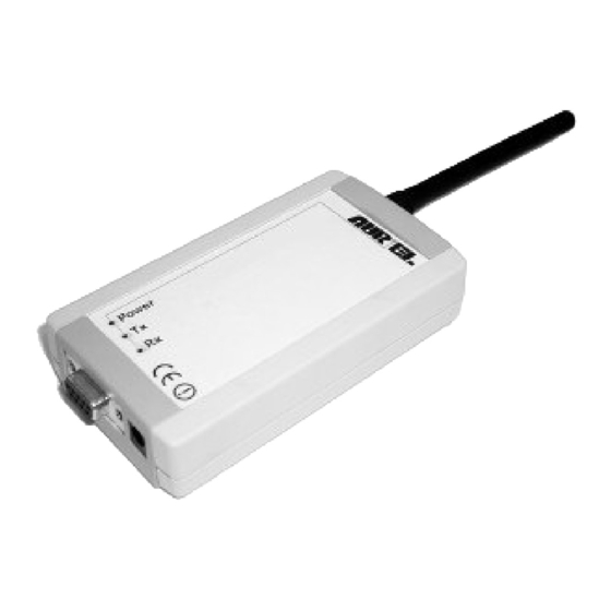
Single channel data transceiver module WIZ2-434
Available models:
WIZ2-434-RS: data input by RS232 (±12V) logic, 9-15V supply
•
WIZ2-434-RSB: same as above , but in a plastic shell.
•
The WIZ2-434-x modules are intelligent transceivers that support a digital data packet transfer of any length
(1-96 bytes).
The data transferred to the remote unit are error-free since, at the arrival, are verified and confirmed.
Half-duplex serial connection with RS232 protocol, with a speed range programmable (9600, 19200,
•
57600, 115200 b/s)
Data's packet length: 1-96 bytes
•
Packet validity control at the reception
•
RF connection through a 433.92 MHz band
•
2FSK modulation
•
Status LED (Power ON, TX, RX)
•
It complies with ETSI 300-220 regulations
•
9-15 V power supply
•
Technical features are subject to change without notice. AUR°EL S.p.A does not assume responsibilities for any damage caused by the device's misuse.
AUR°EL S.p.A. Via Foro dei Tigli, 4 - 47015 Modigliana [FC] – ITALY
Tel.: +390546941124 – Fax: +390546941660
http://www.aurel.it
- email:
lab-el@aurel.it
WIZ2-434
Instruction Manual
Rev. D, 31-01-2003
Page 1 of 14
Advertisement
Table of Contents

Related Manuals for AUREL WIZ2-434


Summary of Contents for AUREL WIZ2-434
- Page 1 WIZ2-434-RSB: same as above , but in a plastic shell. • The WIZ2-434-x modules are intelligent transceivers that support a digital data packet transfer of any length (1-96 bytes). The data transferred to the remote unit are error-free since, at the arrival, are verified and confirmed.
-
Page 2: Table Of Contents
WIZ2-434 Instruction Manual TABLE OF CONTENTS INTRODUCTION • 1. WIZ2-434-RS MODULES LAYOUTS • 2. ADDRESSING • 2.1 CONVERSATION ADMINISTRATION BETWEEN UNITS. • 2.2 MASTER AND SLAVE MODULES: SUMMARY • 3. PROGRAMMING • 3.1 WRITE • 3.2 READ • 3.3 PROGRAMMING PROCEDURE •... - Page 3 Instruction Manual Introduction WIZ2-434-x modules allow to connect, via radio, two or more units; they supply a complete radio frequency system, by integrating receiver, transmitter and antenna and by indipendently administrating a low level packaging of the data sent from a control unit (for instance a Personal Computer), and the managing functions of the radio link interconnection.
- Page 4 WIZ2-434 Instruction Manual 1. Lay-out The WIZ2-434-RS model foresees a 9-15V voltage range, supplied to the DC (1) connector and signals in RS232 logic on the female, 9 pins D (2) connector. WIZ2-434-RS XTR-434 9-15V DC supply connector (internal Vcc,...
-
Page 5: Addressing
WIZ2-434 Instruction Manual 2. Addressing The WIZ2 modules are conceived to be applied in a master–slave system (255 maximum slave number). The distinction between master and slave units is of software type, according to the address contained in the ADDRESS register: ADDRESS = 0: system’s MASTER module;... -
Page 6: Conversation Administration Between Units
WIZ2-434 Instruction Manual 2.1 Conversation administration betw een units Illustrated here below is the addresses management procedure in a master–slave conversation. In this specific example reference is made to slave module with 8 address: SLAVE MASTER 8,<H→R <H→R 8,<H→R MASTER SLAVE 8,<H←R... - Page 7 WIZ2-434 Instruction Manual This procedure is good for WIZ2 modules’ use in the industry, where PLCs can be instructed to operate on machines or questioned to monitor sizes. Being not equipped with the adequate logic, in order to handle the...
-
Page 8: Master And Slave Modules: Summary
WIZ2-434 Instruction Manual 2.3 MASTER AND SLAVE MODULES: ( SUMMARY) MASTER SLAVE It places the address at the head of the data packet → → RF It removes the address from the data packet head → → RS232 It verifies the destination address... -
Page 9: Read
3.4 REGI STERS Here below is reported the list of the registers utilized for the WIZ2-434-x modules and their functions. Technical features are subject to change without notice. AUR°EL S.p.A does not assume responsibilities for any damage caused by the device’s misuse. -
Page 10: Address ($00)
WIZ2-434 Instruction Manual 3.4.1 ADDRESS ( $00) The ADDRESS module contains the WIZ2 module’s address. It corresponds to the location $00 of the EEPROM memory of the microcontroller. The values contained in the register could be: 0: the unity is the MASTER of the system •... - Page 11 WIZ2-434 Instruction Manual The register’s contents may be changed by entering the command: # 3 <new_value> To read the register’s contents the command sequence is: For the programming procedures please refer to para.: 3.3 Note It is suggested to verify, in advance, the RS232 characteristics of the unity connected to the WIZ2 module and to adequately programme such register.
-
Page 12: Programming Jumper
WIZ2-434 Instruction Manual 4. Programming Jumpers To reach the 3 programming jumpers carefully remove the front cover of the box (RSB model). Programming jumpers By closing JP3 from DATA MODE (data transreceiving ) the system switches to PROGRAMMING MODE. Data speed... -
Page 13: Appendix A: Connections
WIZ2-434 Instruction Manual APPENDIX A: CONNECTIONS A.1 RS232 SERI AL CONNECTI ON The WIZ2 modules converse with external devices through a 9 pins RS232 serial interface. The handshaking signals between connected units, with an RS232 protocol, are not utilized by WIZ2 modules. - Page 14 WIZ2-434 Instruction Manual APPENDI X B: MASTER AND SLAVE MODULES; THEIR USE IN A POLLI NG TYPE QUESTIONING SYSTEM SLAVE 1 MASTER . . . n SLAVES In a polling system the unity connected to the master module administrates the slaves’ questioning sequence, deciding the timing and the addresses of the remote units to be monitored.
Need help?
Do you have a question about the WIZ2-434 and is the answer not in the manual?
Questions and answers