Table of Contents
Advertisement
Available languages
Available languages
Quick Links
Advertisement
Table of Contents

Related Manuals for Blain Hydraulics SEV


Summary of Contents for Blain Hydraulics SEV
- Page 1 Smart Servo Electronic Valve Handbuch...
- Page 2 Blain Hydraulics. Moreover, Blain Hydraulics reserves the right to change the information contained in this manual without any notice Every precaution has been taken in the preparation of this manual. Nevertheless, Blain Hydraulics assumes...
-
Page 3: Table Of Contents
INHANLTSVERZEICHNIS Allgemeine informationen ..........................4 Sicherheits- und allgemeine Hinweise ....................4 Einleitung zum Produkt ........................4 Garantieinformationen ........................4 SEV Karte ..............................5 Erklärungen zu den LEDs ........................6 SEV Ventil ..............................7 Ventilerläuterungen .......................... 10 Eletrische Installation ..........................12 Ventileinstellungen ............................ -
Page 4: Allgemeine Informationen
1.3 GARANTIEINFORMATIONEN Blain's SEV User Manual is provided for qualified personnel, who are competent in installing, adjusting and servicing of hydraulic elevators. Blain Hydraulics assumes no liability for any personal injury, property damage, losses or claims arising from in appropriate use of its product or incompetence of the installer. -
Page 5: Sev Karte
SEV User Manual 2. SEV KARTE DIP-Schlalter (für Modus) Eingangssignale Speicherkarte Ausgangssignale Jumper für Software-Update Fehlerrelais-Ausgang Seriennummer Karte (auf Rückseite) Versorgungsspannung 24 V DC / 18 V AC Durchfluss-Sensoreinstellung Fehler-LED (rot) / Warnungs-LED (orange) Temperatursensor-Anschluß Power LED (grün) Drucksensor-Anschluß Bestätigungs- oder OK-Button Durchfluss-Anschluß... -
Page 6: Erklärungen Zu Den Leds
SEV User Manual 2.1 ERKLÄRUNGEN ZU DEN LEDS STATE LED The orange state LED flashes slowly. Any other behaviour is related communication WLAN LED problems and reflects a defect. Green Wenn DIP- Schalter “1” eingeschalten ist, blinkt die blaue LED. -
Page 7: Sev Ventil
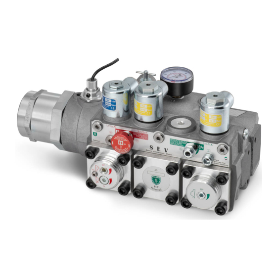
SEV User Manual 3. SEV VENTIL The Blain Servo Electronic Valve (SEV) is controlled by closed loop digital electronics, providing consistent acceleration and deceleration of hydraulic elevators largely independent of load and oil temperature. An electronic card regulates the performance of the car via proportional solenoid valves. - Page 8 SEV User Manual 1” SEV 1½” SEV 2” SEV Figure 3: SEV Ventilabmessungen Optionales Zubehör Notstromspule Überlast-Schalter CSA Spule Minderdruckschalter Schlaffseilverhinderung Kugelhahn Handpumpe Figure 4: Hydraulikschema Steuerelemente Senkeinstellungen Magnetventil - Senkfahrt U Umlaufkolben 7 Begrenzung: max. Senkgeschw. Magnetventil - Hauptsenkfreigabe V Rückschlagnemtil...
- Page 9 SEV User Manual Figure 5: Schnittansicht SEV Ventil Kabine Zylinder Anschlüsse Pumpe Tank Zylinder Horizontaler Schnitt Pilotdruck-Kammern Senkrechter UC Umlaufkammer Schnitt XC Senkventilkammer Einstellung “AUF” AT Hubtrim (Seite 13) Einstellung “AB” CT Senktrim (Seite 13) Begrenzung: max. Senkgeschw. Notablass-Geschwindigkeit Steuerelemente...
-
Page 10: Ventilerläuterungen
SEV User Manual 3.1 VENTILERLÄUTERUNGEN Hubfahrt With an Up signal, the pump-motor is energized and the electronic card´s Up program starts simultaneously. Oil flows through orifice 2 into the bypass pilot chamber UC. Coil A is energized and solenoid A (normally open) from the card and partially closes, reducing the volume of pilot oil flowing out from the bypass pilot chamber. - Page 11 Up and down inspection speeds can be independently adjusted between 0.05 m/s and 0.30 m/s. SEV-Ventile sind bereits getestet und eingestellt. Bitte alle elektrischen Verbindungen prüfen, ehe Daten der Karte geändert werden. Test that the correct coil is energized by removing the nut and raising the coil slightly to feel magnetic pull.
-
Page 12: Eletrische Installation
SEV User Manual ELETRISCHE INSTALLATION Schaltschrank SEV Karte Spann- ung für D-Spule Internes Fehlerrelais Senkschleich (Spule D) 11 12 13 16 17 18 19 20 4 5 6 7 8 9 10 1 2 3 Senkschleich Senkvoll Hubvoll Hubschleich 24 V DC... -
Page 13: Ventileinstellungen
Installation of the SEV Card into the Controller The SEV Card can be connected into any standard type hydraulic elevator controller. The power to coils A and C is supplied from the card. Power to coil D is directly provided by the main controller. Page 11, shows the detailed wiring diagram for connecting the SEV card to the elevator controller. -
Page 14: Durchfluß Sensor Und Magnetventileinstellung
SEV User Manual DURCHFLUß SENSOR UND MAGNETVENTILEINSTELLUNG Einstellung der Magnetventile A und C (werksseitig bereits eingestellt) Ein Einstellen der Magnetventils ist notwendig, falls Teile des Magnetventils beim Service gewechselt wurden. Das Einstellen ist notwendig, damit das Losfahren der Kabine zügig und ruckfrei erfolgt. Die Fahrtrichtung wird durch die Farbe der LEDs angezeigt. - Page 15 SEV User Manual For radial adjustment of the sensor loosen the bushing lock (3mm Allen key) nut (4), without turning the sensor bushing (2). Operate the Bushing lock nut elevator to run Up and Down at leveling speed. Measure [32 mm (1 1/4”) spanner] the speed with stop watch or tachometer.
-
Page 16: Wlan Verbindungen & Sicherheit
SEV User Manual 7. WLAN VERBINDUNGEN & SICHERHEIT Die Elektronik Karte des SEV nutzt das Verbindungsprotokoll IEEE Standard 2.4GHz, 802.11 b/g/n. Generell können alle modernen Smart Geräte (Telefon/Tablet/Laptop) mit dem WLAN ACCESS Point der Karte mittels diesem Protokolls kommunizieren. Im Auslieferungszustand wird die SEV Karte wie im Bild unten ausgeliefert. -
Page 17: Installation
SEV User Manual 8. INSTALLATION 8.1 MENÜSTRUKTUR DER SOFTWARE Ⅱ Ⅰ Ⅲ Sprache Einstellungen Status Meldungen Datum/Uhrzeit 1. Datum / Uhrzeit 1. Deutsch einstellen Metrisch 1. Status 2. Einheiten Imperial 2. Englisch Verstäkungsfaktor 2. Meldungen Dither Verstärker 3. Ventil- Geschwindigkeits einstellungen 3. -
Page 18: Hauptmenü
“Data collection”, “Settings” and “State / Notifications” will be explained in detail. As the software for interacting with the SEV card resides on the webserver and on the card itself, no additional software installation on the smart device is necessary. This unique feature allows the user to use any smart device;... - Page 19 SEV User Manual The “MAIN MENU” allows access to the “Install wizard”, the “Data collection”, the “Settings” and the “State/notifications” sub menus. The “Install wizard” is being used to assist during valve setup and serves as a step by step guide to help users entering the complete and correct necessary elevator data.
- Page 20 Furthermore some flow is needed by the SEV to regulate and provide constant speed and travel time. 90 % efficiency is an approximated value.
- Page 21 ←Links Im Menüpunkt “Datensammlung” werden in verschiedenen Untermenüs die eingestellten Daten der SEV-Karte zum Editieren angezeigt. Die Daten können durch anklicken von “Aufzugsdaten” oder “Fahrdaten” geändert werden. Zusätzlich ist hier der Zugang zur Funktion “Lernfahrt”, zum “Log- buch”...
- Page 22 SEV User Manual ←Links Im Bereich “Fahrdaten” können die Parameter zu den Geschwindig- keiten, Beschleunigungen sowie Abbremsungen für Hub- und Senkrichtung eingesehen bzw. geändert werden. Recht→ Die Funktion “Lernfahrt” kann für eine genauere Anzeige der gefahrenen Geschwindigkeit verwendet werden. Die jeweilige Geschwindigkeit und Richtung der letzten Fahrt ist auswählbar.
- Page 23 Looking at the travel graph section there are three different views to choose from. Travel graphs give the customer and the Blain Hydraulics tech support the possibility to run system diagnostics and check for possible problems. On the left there are two examples of travel graphs in this so called “View 1”.
- Page 24 SEV User Manual ←Links III.1 III.2 In diesem Menüpunkt werden die aktuellen Status verschiedener Daten angezeigt. Die Sensorwerte für Druck und Temperatur, sowie die Eingangs- (A, B, C, D, I) und Ausgangssingnale (Hub und Snek). Der Spulenwert sollte etwa 2100 digits während der Konstantfahrt in Voll- oder Schleichfahrt betragen.
- Page 25 ID in reference to their elevator system. “Sensor calibration” and “Sensor table” as well as “Hardware ID” are for Blain Hydraulics only when setting up the valve for customers. Version: 07/2020...
-
Page 26: Update
SEV User Manual 8.3 UPDATE The jumper on the SEV card should bet set to Alternatively the software can be updated by bridged mode to allow the electronic card to be pressing the update button in the status menu flashed with new firmware. A micro SD card with new without disconnecting the power supply. -
Page 27: Fehler
Card Internal Relay R1 - Evacuation of passengers Important If there is a major fault interfering with the normal operation of the SEV card when travelling between floors, power supply to coil A or C will automatically be interrupted. During Up travel the motor and during Down travel coil D (Down start/stop) remain energised unless the SEV relay R1 signals otherwise. -
Page 28: Monitoring
Ansichten zur Begutachtung zur Verfügung. Ansicht 1 ist die gebräuchlichste und wird vom Anwender und Blain Hydraulics genutzt um die Fahreingenschaften des Aufzugs zu anylysieren. Angezeigt werden die Soll- und Ist-Geschwindigkeit für Hub- und Senkfahrt, die Leistung der Magnetspulen und die Beschleunigungswerte. - Page 29 SEV User Manual 4 – nach Links / Reinzoomen 5 – Wechsel zw. Fadenkreuz und Lupe 6 – nach Rechts / Rauszoomen 7 – Kanal wechseln Abhängig vom ausgewählten Kanal (1) paßt sich die Skalierung (2) automatisch an. Werte der Y-Achse hängen vom auswählten Maßsyststem des Menüpunkts “Einstellungen”...
-
Page 30: Auswahldiagramme - Einsatzgrößen
SEV User Manual AUSWAHLDIAGRAMME – EINSATZGRÖßEN Flow ring R selection Data required when ordering: P, T, Z l/min US gpm Ring size Pump data ports Static pressure empty car 40 – 75 10 – 20 1” G Static pressure with full load ... -
Page 31: Troubleshooting
5. Pressure- Connection problem. temperature sensor SEV card. Change sensor if necessary. not functioning or no Flip switch Nr. 2 on SEV card to use reading on main Sensor defect. SEV valve without p-T sensor. Change menu. sensor (middle flange). -
Page 32: Hubfahrt
Short delay valve is not closing. Change short delay valve. Bypass flow guide 'U' too small. Insert larger bypass flow guide. O-Ring 'UO' on bypass flow guide 'U' is Change O-Ring → look at SEV spare 2. UP start is too leaking. parts list. hard. -
Page 33: Senkfahrt
Change O-Ring → SEV spare parts list. to inner leakage O-Ring 'WO' of check valve 'V' leaking. Change O-Ring → SEV spare parts list. Inner O-Ring 'FO' in flange '4F' leaking. Change O-Ring → SEV spare parts list. O-Ring 'HO' of manual lowering 'H' Change O-Ring 'HO' or change manual leaking. -
Page 34: Durchfluß Zu Geschwindigkeit, Druck Zu Gewicht
SEV User Manual DURCHFLUß ZU GESCHWINDIGKEIT, DRUCK ZU GEWICHT Version: 07/2020... - Page 35 SEV User Manual Version: 07/2020...
- Page 36 SEV User Manual Version: 07/2020...
Need help?
Do you have a question about the SEV and is the answer not in the manual?
Questions and answers