Table of Contents
Advertisement
Quick Links
Advertisement
Table of Contents

Subscribe to Our Youtube Channel
Related Manuals for Blain Hydraulics SEV07


Summary of Contents for Blain Hydraulics SEV07
- Page 2 Blain Hydraulics. Moreover, Blain Hydraulics reserves the right to change the information contained in this manual without any notice Every precaution has been taken in the preparation of this manual. Nevertheless, Blain Hydraulics assumes...
-
Page 3: Table Of Contents
SEV User Manual TABLE OF CONTENTS General information ............................. 4 Safety precautions & general warnings ....................4 Product introduction ..........................4 Warranty information .......................... 4 The SEV card .............................. 5 LED Diagnostics ..........................6 The SEV valve ............................. 7 Valve operation ..........................10 Electrical installation .......................... -
Page 4: General Information
Blain's SEV User Manual is provided for qualified personnel, who are competent in installing, adjusting and servicing of hydraulic elevators. Blain Hydraulics assumes no liability for any personal injury, property damage, losses or claims arising from in appropriate use of its product or incompetence of the installer. -
Page 5: The Sev Card
SEV User Manual 2. THE SEV CARD Mode switch Input signals Memory card slot Output signals Jumper for data upload Error relay Type plate Power supply 24 V DC / 18 V AC Flow sensor adjustment feedback Error LED (red) / warning LED (orange) Temperature sensor connection Power LED (green) Pressure sensor connection... -
Page 6: Led Diagnostics
SEV User Manual 2.1 LED DIAGNOSTICS STATE LED SWITCH LED The orange state LED flashes When switch “1” is set slowly. Any other behaviour is „ON“, related communication flashes slowly. As soon problems and reflects a defect. as a WiFi connection to Green smart device... -
Page 7: The Sev Valve
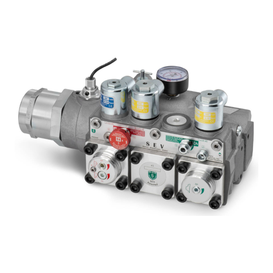
SEV User Manual 3. THE SEV VALVE The smart Servo Electronic Valve (SEV) is controlled by closed loop digital electronics, providing consistent travel characteristics elevators irrespective of load and oil temperature variations. An electronic card regulates the performance of the car via proportional solenoid valves. The elevator operation can be monitored, recorded and adjusted by a smart device using Wi-Fi connectivity. - Page 8 SEV User Manual 1” SEV 1½” SEV 2” SEV Figure 2: SEV valve dimensions Optional Equipment Emergency coil High pressure switch CSA coils Low pressure switch Slack rope valve Ball valve Hand pump HX/MX Auxiliary down valve Hydraulic circuit SEV 07 SEV 05 Control Elements Down adjustments...
- Page 9 SEV User Manual Cut section view of the SEV valve SEV 05 SEV 07 Cabin Cylinder Connections Pump port Tank port Cylinder port Horizontal section Pilot pressure chambers Vertical UC Bypass chamber section XC Down valve chamber Adjustment UP AT Up trim (page 13) Adjustments DOWN CT Down trim (page 13) Full speed limitation...
-
Page 10: Valve Operation
SEV User Manual Control elements Solenoid Up control Pressure-temp.-sensor Check valve Solenoid Down control Flow meter Down valve Solenoid Down start/stop Flow ring Manual lowering valve Early start valve Pressure relief valve Pilot orifice Up Manual lowering Bypass valve Pilot orifice Down Flow sensor 3.1 VALVE OPERATION UP operation... - Page 11 SEV User Manual INSPECTION Speed Besides full speed and levelling speed, an optional inspection speed is available by the SEV system. Up and down inspection speeds can be independently adjusted between 0.05 m/s and 0.30 m/s. Initial Operations Valves are already adjusted and tested. Check electrical operation before changing valve settings. Test that the correct coil is energized by using metal parts to feel magnetic pull.
- Page 12 SEV User Manual SEV adjustments and explosion drawing SEV 07 SEV 05 Adjustments Highlighted valve parts Trim solenoid C Manual lowering Pressure relief valve Down valve Trim solenoid A Down levelling valve Slack rope valve (optional) Check valve Manual lowering speed Bypass valve Maximum speed limitation Bypass adjustment...
-
Page 13: Electrical Installation
SEV User Manual 4. ELECTRICAL INSTALLATION Lift Controller SEV card Power supply coil D SEV 07 only Card internal relay 11 12 13 16 17 18 19 20 Down levelling (coil D) 1 2 3 4 5 6 7 8 9 10 Down levelling Down full speed Up full speed... -
Page 14: Control Valve Installation
SEV User Manual 5. CONTROL VALVE INSTALLATION Check the following: 1. The flow on the data plate of the valve complies with the flow rate of the pump (±10 %). 2. The minimum and maximum static pressures on the valve data plate is in accordance with those of the elevator. -
Page 15: Flow Sensor And Solenoid Adjustments
SEV User Manual 6. FLOW SENSOR AND SOLENOID ADJUSTMENTS Adjustment of solenoid power levels A and C (already factory adjusted) The adjustment of the solenoid power level is necessary if parts of the solenoids have been changed during servicing. Solenoid power level has to be adjusted to ensure the valves best possible performance and to produce a quick and smooth initial movement of the car away from the floor. -
Page 16: Wi-Fi Connectivity & Security
SEV-05 valves. The ON position is to be used when using SEV-07 valves with pressure and temperature sensors. Switch 3 – Reserved for Blain Hydraulics. Switch 4 – not in use for the time being To connect with the SEV card using your smart device, In order to safeguard unauthorized access to the ensure the switch 1 to be in ON position. -
Page 17: Setup Procedure
SEV User Manual 8. SETUP PROCEDURE 8.1 SOFTWARE MENU OVERVIEW Ⅲ Ⅴ Ⅰ Language Settings State Notifications 1. Date / Time Set date and time 1. German 2. Units SI / Imperial Gain value 1. State Dither amplifier 2. English 3. -
Page 18: Main Menu
SEV User Manual 8.2 MAIN MENU Main Menu button The language of the software can be changed by Once the preferred language has been selected, go pressing the flag in the upper left corner. From the to “Settings” to set the date and time and choose main menu the easy to use “Install wizard”... - Page 19 SEV User Manual The “MAIN MENU” allows access to the “Install wizard”, the “Data collection”, the “Settings” and the “State/notifications” sub menus. The “Install wizard” is being used to assist during valve setup and serves as a step by step guide to help users entering the complete and correct necessary elevator data.
- Page 20 SEV User Manual II.3 II.4 ←Left Enter the pump performance data provided by the manufacturer. Due to changes in load and oil viscosity the pump will not always deliver its full flow. Furthermore some flow is needed by the SEV to regulate and provide constant speed and travel time.
- Page 21 Warning: Adjustments for Gain and Dither should only be done once Blain Hydraulics tech support has been consulted. Speed mode can be either set to Constant Speed Mode or Energy Saving Mode. The...
- Page 22 From this menu you can reset different data you previously entered and reset everything to factory settings. The factory settings are set by the customers themselves or Blain Hydraulics according to customer data. Additionally settings can be uploaded to and downloaded from the SD card.
- Page 23 SEV User Manual ←Left III.6b III.6b Before the “rupture valve test” is carried out, a warning is shown. After the warning perception there is a short briefing before the screen on the right appears. This test should only be performed by qualified personnel! Right→...
- Page 24 SEV User Manual ←Left IV.3 IV.4 The “Travel data” section provides an overview about the selected speeds and accelerations for Up, Down and Inspection travel. Values can be changed according to customer´s wishes. Right→ The “log book” offers information about the runs made. Each run can be identified by date and time and selected to inspect its travel graph.
- Page 25 SEV User Manual ←Links IV.5 IV.5a The „trouble shooting“ gives hints and advice on how to handle most common errors in Up and Down travels. The full list can be found in section 12. Rechts→ Errors always have corresponding symptoms, which can be caused by the control valve.
-
Page 26: Update
SEV User Manual 8.3 UPDATE To perform an update, a micro SD card with a new software version is required. During the update, the green LED of the boot loader flashes very quickly. The process usually takes one to two minutes. As soon as the process is complete, the green and red Boot Loader LEDs are flashing slowly alternately. -
Page 27: Monitoring
Up and Down directions as well as the solenoid power level and the acceleration values are displayed. Examples are given below. View 2 gives a more detailed look into values of the PID controller and will be used mainly by Blain Hydraulics technical support for system diagnostics. - Page 28 SEV User Manual Depending on which channel is chosen (1) the scaling (2) will change automatically. Values shown on the Y- axis relate to the SI or Imperial units selected in the “Settings” accessible form the “MAIN MENU”. Pressing the “Back” button (3) results in a return to the view selection. If a cross-sign can be seen at position number 5, then left (4) and right (6) arrows allow to move along the time axis of the graph.
-
Page 29: Errors
SEV User Manual ERRORS Card Internal Relay R1 - Evacuation of passengers Important If there is a major fault interfering with the normal operation of the SEV card when travelling between floors, power supply to coil A or C will automatically be interrupted. During Up travel the motor and during Down travel coil D (Down start/stop) remain energised unless the SEV relay R1 signals otherwise. -
Page 30: Selection Charts - Valve Inserts
SEV User Manual SELECTION CHARTS – VALVE INSERTS Flow ring R selection Data required when ordering: P, T, Z l/min US gpm Ring size Pump data ports Static pressure empty car 40 – 75 10 – 20 1” G Static pressure with full load ... -
Page 31: Troubleshooting
SEV User Manual TROUBLESHOOTING 12.1 GENERAL ERRORS Valves are already adjusted and tested. Check electrical operation before changing valve settings. Test that the correct coil is energized by using metal parts to feel magnetic pull. Once system is installed correctly, it is ready for operation. Make sure, that all parts are properly mounted after servicing the valve. -
Page 32: Up Direction Travel
SEV User Manual 12.2 UP DIRECTION TRAVEL Problem Cause Recommended Coil 'A' not energized, voltage too low. Lift coil to check magnetic force. Insufficient voltage supplied to SEV Supplied Voltage to SEV card has to be card. 24 V DC. Run elevator with leveling speed in UP Spring preload of solenoid 'A' not direction and set digital value of... -
Page 33: Down Direction Travel
SEV User Manual 12.3 DOWN DIRECTION TRAVEL Problem Cause Recommended Coil 'D' not energized, voltage too low. Lift coil to check magnetic force. Insufficient voltage supplied to SEV Voltage supplied to SEV card is 1. No DOWN start. card. 24 V DC. O-Ring 'UO' of down valve 'X' leaking. -
Page 34: Flow - Pressure Chart (Metric & Imperial)
SEV User Manual FLOW – PRESSURE CHART (METRIC & IMPERIAL) Version: 02/05/2021... - Page 35 SEV User Manual Version: 02/05/2021...
- Page 36 SEV User Manual Version: 02/05/2021...
- Page 37 SEV User Manual Notes: ……………………………………………………………………………………………………………………………. ……………………………………………………………………………………………………………………………. ……………………………………………………………………………………………………………………………. ……………………………………………………………………………………………………………………………. ……………………………………………………………………………………………………………………………. ……………………………………………………………………………………………………………………………. ……………………………………………………………………………………………………………………………. ……………………………………………………………………………………………………………………………. ……………………………………………………………………………………………………………………………. ……………………………………………………………………………………………………………………………. ……………………………………………………………………………………………………………………………. ……………………………………………………………………………………………………………………………. ……………………………………………………………………………………………………………………………. ……………………………………………………………………………………………………………………………. ……………………………………………………………………………………………………………………………. ……………………………………………………………………………………………………………………………. ……………………………………………………………………………………………………………………………. ……………………………………………………………………………………………………………………………. ……………………………………………………………………………………………………………………………. ……………………………………………………………………………………………………………………………. ……………………………………………………………………………………………………………………………. ……………………………………………………………………………………………………………………………. ……………………………………………………………………………………………………………………………. ……………………………………………………………………………………………………………………………. ……………………………………………………………………………………………………………………………. Version: 02/05/2021...
- Page 38 SEV User Manual Notes: ……………………………………………………………………………………………………………………………. ……………………………………………………………………………………………………………………………. ……………………………………………………………………………………………………………………………. ……………………………………………………………………………………………………………………………. ……………………………………………………………………………………………………………………………. ……………………………………………………………………………………………………………………………. ……………………………………………………………………………………………………………………………. ……………………………………………………………………………………………………………………………. ……………………………………………………………………………………………………………………………. ……………………………………………………………………………………………………………………………. ……………………………………………………………………………………………………………………………. ……………………………………………………………………………………………………………………………. ……………………………………………………………………………………………………………………………. ……………………………………………………………………………………………………………………………. ……………………………………………………………………………………………………………………………. ……………………………………………………………………………………………………………………………. ……………………………………………………………………………………………………………………………. ……………………………………………………………………………………………………………………………. ……………………………………………………………………………………………………………………………. ……………………………………………………………………………………………………………………………. ……………………………………………………………………………………………………………………………. ……………………………………………………………………………………………………………………………. ……………………………………………………………………………………………………………………………. ……………………………………………………………………………………………………………………………. ……………………………………………………………………………………………………………………………. Version: 02/05/2021...
- Page 39 SEV User Manual Notes: ……………………………………………………………………………………………………………………………. ……………………………………………………………………………………………………………………………. ……………………………………………………………………………………………………………………………. ……………………………………………………………………………………………………………………………. ……………………………………………………………………………………………………………………………. ……………………………………………………………………………………………………………………………. ……………………………………………………………………………………………………………………………. ……………………………………………………………………………………………………………………………. ……………………………………………………………………………………………………………………………. ……………………………………………………………………………………………………………………………. ……………………………………………………………………………………………………………………………. ……………………………………………………………………………………………………………………………. ……………………………………………………………………………………………………………………………. ……………………………………………………………………………………………………………………………. ……………………………………………………………………………………………………………………………. ……………………………………………………………………………………………………………………………. ……………………………………………………………………………………………………………………………. ……………………………………………………………………………………………………………………………. ……………………………………………………………………………………………………………………………. ……………………………………………………………………………………………………………………………. ……………………………………………………………………………………………………………………………. ……………………………………………………………………………………………………………………………. ……………………………………………………………………………………………………………………………. ……………………………………………………………………………………………………………………………. ……………………………………………………………………………………………………………………………. Version: 02/05/2021...
Need help?
Do you have a question about the SEV07 and is the answer not in the manual?
Questions and answers