Table of Contents
Advertisement
Quick Links
Advertisement
Table of Contents

Related Manuals for Blain Hydraulics SEV


Summary of Contents for Blain Hydraulics SEV
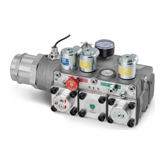
- Page 1 Smart Servo Electronic Valve manual...
- Page 2 Blain Hydraulics. Moreover, Blain Hydraulics reserves the right to change the information contained in this manual without any notice Every precaution has been taken in the preparation of this manual. Nevertheless, Blain Hydraulics assumes...
-
Page 3: Table Of Contents
General information ............................. 4 Safety precautions & general warnings ....................4 Product introduction ..........................4 Waranty information ........................... 4 The SEV card .............................. 5 LED Diagnostics ..........................6 The SEV valve ............................. 7 Valve operation ..........................10 Electrical installation ..........................12 Control valve installation ........................... -
Page 4: General Information
1.3 WARANTY INFORMATION Blain's SEV User Manual is provided for qualified personnel, who are competent in installing, adjusting and servicing of hydraulic elevators. Blain Hydraulics assumes no liability for any personal injury, property damage, losses or claims arising from in appropriate use of its product or incompetence of the installer. -
Page 5: The Sev Card
SEV User Manual 2. THE SEV CARD Mode switch Input signals Memory card slot Output signals Jumper for data upload Error relay Type plate Power supply 24 V DC / 18 V AC Flow sensor adjustment feedback Error / warning LED... -
Page 6: Led Diagnostics
SEV User Manual 2.1 LED DIAGNOSTICS STATE LED The orange state LED flashes slowly. Any other behaviour is related communication SWITCH LED problems and reflects a defect. Green If switch “1” is in „ON“- position, the LED will flash slowly. Once a... -
Page 7: The Sev Valve
SEV User Manual 3. THE SEV VALVE The Blain Servo Electronic Valve (SEV) is controlled by closed loop digital electronics, providing consistent acceleration and deceleration of hydraulic elevators largely independent of load and oil temperature. An electronic card regulates the performance of the car via proportional solenoid valves. - Page 8 SEV User Manual 1” SEV 1½” SEV 2” SEV Figure 3: SEV valve dimensions Optional Equipment Emergency coil High pressure switch CSA coils Low pressure switch Slack rope valve Ball valve Hand pump HX/MX Auxiliary down valve Figure 4: Hydraulic circuit...
- Page 9 SEV User Manual Figure 5: Cut section view of the SEV valve Cabin Cylinder Connections Pump port Tank port Cylinder port Horizontal section Pilot pressure chambers Vertical UC Bypass chamber section XC Down valve chamber Adjustment UP AT Up trim (page 13)
-
Page 10: Valve Operation
Up operation of the elevator. DOWN operation (Caution! Voltage for coil D comes directly from the elevator´s controller, not from the SEV card) With a Down signal, coil D is energized, solenoid D (normally closed) opens and the electronic card´s Down program starts simultaneously. - Page 11 To adjust, turn K all the way ‘in’, then turn K ‘out’ until the empty car just begins to descend, then turn out another half a turn to ensure that with cold oil the empty car can be lowered as required. Figure 6: SEV adjustments and explosion drawing Adjustments...
-
Page 12: Electrical Installation
SEV User Manual 4. ELECTRICAL INSTALLATION Lift Controller SEV card Voltage coil D Card internal relay 11 12 13 16 17 18 19 20 Down levelling (coil D) 1 2 3 4 5 6 7 8 9 10 Down levelling... -
Page 13: Control Valve Installation
Installation of the SEV Card into the Controller The SEV Card can be connected into any standard type hydraulic elevator controller. The power to coils A and C is supplied from the card. Power to coil D is directly provided by the main controller. Page 11, shows the detailed wiring diagram for connecting the SEV card to the elevator controller. -
Page 14: Flow Sensor And Solenoid Adjustments
SEV User Manual 6. FLOW SENSOR AND SOLENOID ADJUSTMENTS Adjustment of solenoid power levels A and C (already factory adjusted) The adjustment of the solenoid power level is necessary if parts of the solenoids have been changed during servicing. Solenoid power level has to be adjusted to ensure the valves best possible performance and to produce a quick and smooth initial movement of the car away from the floor. -
Page 15: Wi-Fi Connectivity & Security
(phone/tablet/laptop) can communicate with the Wi-Fi access point on the card using these protocols. The SEV card is delivered using the default settings as shown in the picture below. Switch 1 - The Wi-Fi switch in ON position allows communication with the electronic card using a smart phone. -
Page 16: Setup Procedure
SEV User Manual 8. SETUP PROCEDURE 8.1 SOFTWARE MENU OVERVIEW Ⅱ Ⅰ Ⅲ Language Settings State Notifications 1. Date / Time Set date and time 1. German 2. Units Imperial 1. State Gain value 2. English Dither amplifier 3. Valve settings 2. -
Page 17: Main Menu
“Data collection”, “Settings” and “State / Notifications” will be explained in detail. As the software for interacting with the SEV card resides on the webserver and on the card itself, no additional software installation on the smart device is necessary. This unique feature allows the user to use any smart device;... - Page 18 SEV User Manual The “MAIN MENU” allows access to the “Install wizard”, the “Data collection”, the “Settings” and the “State/notifications” sub menus. The “Install wizard” is being used to assist during valve setup and serves as a step by step guide to help users entering the complete and correct necessary elevator data.
- Page 19 Furthermore some flow is needed by the SEV to regulate and provide constant speed and travel time. 90 % efficiency is an approximated value.
- Page 20 SEV User Manual ← Left IV.7 IV.8 The inspection travel speed for Up and for Down direction can be set here. Inspection speed is sometimes referred to as the second slow speed, which can be used for inspections or short floor distances.
- Page 21 SEV User Manual ←Left The “Travel data” section provides an overview about the selected speeds and accelerations for Up, Down and Inspection travel. Values can be changed according to customer´s wishes. Right→ The “Teach run” function provides an option to fine-tune the Up and...
- Page 22 Looking at the travel graph section there are three different views to choose from. Travel graphs give the customer and the Blain Hydraulics tech support the possibility to run system diagnostics and check for possible problems. On the left there are two examples of travel graphs in this so called “View 1”.
- Page 23 SEV User Manual ←Left III.1 III.2 In this menu you will find the actual state of the elevator. The sensor values for pressure and temperature are displayed as well as input (A, B, C, D, I) and output (Up, Down) signals. The coil value...
- Page 24 IP address. While the IP address is fixed, SSID and password can be changed to your liking, making it possible to customize your SEV so only you can connect and communicate. Right→ The “Pro” menu is reserved for OEM´s and Blain Hydraulics, since...
-
Page 25: Update
SEV User Manual 8.3 UPDATE The jumper on the SEV card should bet set to Alternatively the software can be updated by bridged mode to allow the electronic card to be pressing the update button in the status menu flashed with new firmware. A micro SD card with new without disconnecting the power supply. -
Page 26: Errors
Elevator surpasses the floor level. Errors 3-7 do not have influence on the operation of the elevator. As long as the power supply to the SEV card is maintained, errors will be saved and the red LED will remain illuminated. The error indication can be cancelled one after the other in reversed order of occurrence (last error first) by pressing OK button on the SEV card or by erasing the error messages within the “notifications”... -
Page 27: Monitoring
View 2 gives a more detailed look into values of the PID Figure 10.3 controller and will be used mainly by Blain Hydraulics tech support for system diagnostics. View 3 shows the pressure and temperature changes during the travel. Each view has the same basic layout and buttons to fulfil the same functions. - Page 28 SEV User Manual Depending on which channel is chosen (1) the scaling (2) will change automatically. Values shown on the Y- axis relate to the SI or Imperial units selected in the “Settings” accessible form the “MAIN MENU”. Pressing the “Back” button (3) results in a return to the view selection. If a cross-sign can be seen at position number 5, then left (4) and right (6) arrows allow to move along the time axis of the graph.
-
Page 29: Selection Charts - Valve Inserts
SEV User Manual SELECTION CHARTS – VALVE INSERTS Flow ring R selection Data required when ordering: P, T, Z l/min US gpm Ring size Pump data ports Static pressure empty car 40 – 75 10 – 20 1” G Static pressure with full load ... -
Page 30: Troubleshooting
5. Pressure- Connection problem. temperature sensor SEV card. Change sensor if necessary. not functioning or no Flip switch Nr. 2 on SEV card to use reading on main Sensor defect. SEV valve without p-T sensor. Change menu. sensor (middle flange). -
Page 31: Up Direction Travel
Short delay valve is not closing. Change short delay valve. Bypass flow guide 'U' too small. Insert larger bypass flow guide. O-Ring 'UO' on bypass flow guide 'U' is Change O-Ring → look at SEV spare 2. UP start is too leaking. parts list. hard. -
Page 32: Down Direction Travel
Change O-Ring → SEV spare parts list. to inner leakage O-Ring 'WO' of check valve 'V' leaking. Change O-Ring → SEV spare parts list. Inner O-Ring 'FO' in flange '4F' leaking. Change O-Ring → SEV spare parts list. O-Ring 'HO' of manual lowering 'H' Change O-Ring 'HO' or change manual leaking. -
Page 33: Flow - Pressure Chart (Metric & Imperial)
SEV User Manual FLOW – PRESSURE CHART (METRIC & IMPERIAL) Version: 02/2020... - Page 34 SEV User Manual Version: 02/2020...
- Page 35 SEV User Manual Version: 02/2020...
Need help?
Do you have a question about the SEV and is the answer not in the manual?
Questions and answers