Table of Contents
Advertisement
Quick Links
EA200A
Generator Automatic Voltage Regulator
Operation Manual
200 Amp Automatic Voltage Regulator
Compatible with Self Excited Carbon Brush Type Generators
Full Wave & Half Wave Version Selectable
KUTAI ELECTRONICS INDUSTRY CO., LTD.
TEL : +886-7-8121771
FAX : +886-7-8121775
Website :
www.kutai.com.tw
Headquarters : No.3, Ln. 201, Qianfu St., Qianzhen Dist., Kaohsiung City 806037, Taiwan
Advertisement
Table of Contents

Subscribe to Our Youtube Channel
Related Manuals for Kutai electronics EA200A


Summary of Contents for Kutai electronics EA200A
- Page 1 Generator Automatic Voltage Regulator Operation Manual 200 Amp Automatic Voltage Regulator Compatible with Self Excited Carbon Brush Type Generators Full Wave & Half Wave Version Selectable KUTAI ELECTRONICS INDUSTRY CO., LTD. TEL : +886-7-8121771 FAX : +886-7-8121775 Website : www.kutai.com.tw...
-
Page 2: Table Of Contents
SECTION 7:OVER TEMPERATURE PROTECTION ..................14 SECTION 8:EXTERNAL EMERGENCY STOP POWER GENERATION ............14 SECTION 9:WIRING DIAGRAM........................15 SECTION 10:TROUBLE SHOOTING ....................... 16 SECTION 11:APPENDIX ........................... 17 11.1 Internal drawing............................17 11.2 EP4-1 Operation Manual ........................18 11.3 Internal wiring diagram ..........................20 ___________________________________________________________________________________________ EA200A... -
Page 3: Section 1:Specification
※ This Automatic Voltage Regulator is not equipped with loss-Sensing Protection function / Over Excitation Protection. An additional Over-Voltage Protection device for load may be required to avoid possible damage to the equipment or severe personal injury or death. ※ All AC voltage readings are average value only. ___________________________________________________________________________________________ EA200A... -
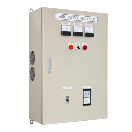
Page 4: Section 2:Outline Drawing
(Figure 1), avoid high temperature, moisture, and location where AVR cannot be easily reached. ※ AVR heat sink may reach a high temperature (above 60 ˚C) when AVR is powered, do not touch or ground AVR heat sink. ___________________________________________________________________________________________ EA200A... -
Page 5: Section 3:Internal Specification
Field voltage meter Generator voltage meter (Sensing voltage) Over temperature alarm indicator Auto / Manual Field Flash selector Over temperature shutdown indicator Power input MCCB EA45AF-2 Control Module 50 Hz / 60Hz Frequency Selector Half Wave / Full Wave selector ___________________________________________________________________________________________ EA200A... - Page 6 SCR 1 and Heatsink Terminal TB4 (for internal wiring) Terminal TB5 (for sensing voltage and voltage selector for Fan) Terminal TB1 (for Excitation output) Power input MCCB Terminal TB2 Terminal TB3 Sensing voltage / Fan Power Transformer (under the iron frame) ___________________________________________________________________________________________ EA200A...
-
Page 7: Section 4:Terminal
Oil Pressure Switch for Automatic Flashing Unit (Refer to Section 6) External Emergency Stop Switch to Stop Power Output to Generation EMERGENCY OPEN ː Normal Operation, CLOSE ː STOP Power Output to Generation SHUTDOWN (Refer to Section 8) ___________________________________________________________________________________________ EA200A... -
Page 8: Tb3 Signal Input / Output Terminal
※ The A1 and A2 signal must be isolated from the power. ※ All the power of EA200A protection system were supplied by 24Vdc, the B+ and B- terminal must be connected correctly, otherwise all the protection, Self-Excited, and the Field Current meter cannot be used. -
Page 9: Section 5:Setting And Adjustment Before Operate
※ SENSING VOLT must be selected to the closest voltage on S1 & S2 ATTENTION ※ The factory preset FAN VOLT is 277Vac, SENSING VOLT factory preset is 110Vac. Make adjustment before operation on the first time installation. ___________________________________________________________________________________________ EA200A... -
Page 10: Ea45Af Adjustment
Adjust the generator frequency to normal speed. ATTENTION ※ Improper setting of under-frequency protection could cause the output voltage of the unit to drop or become unstable under with changes in load. Avoid making any changes to the U/F setting unless necessary. ___________________________________________________________________________________________ EA200A... - Page 11 If generator excitation voltage is greater than 60Vdc in Full load, must select Full Wave output. If generator excitation voltage is less than 30Vdc, must select Half Wave output. ATTENTION ※ Do not change the Under Frequency setting or Half Wave / Full Wave setting when generator is running. ___________________________________________________________________________________________ EA200A...
-
Page 12: Ea45C Adjustment
The TRIM knob is used to adjust the influence ratio of the DC input voltage to the generator voltage, the counterclockwise to the end is 0, and clockwise to the end is +/-10% (Max.). ATTENTION ※ The A1 and A2 signal must be isolated from the power. ___________________________________________________________________________________________ EA200A... -
Page 13: Eb500 Adjustment
EP4-1 is a DC voltage abnormal warning relay Factory Preset Value Under volt:20V Over volt:28V Under voltage delay time:5s Over voltage delay time:5s DIP SW:1 – OFF、2 – OFF、3 – ON、4 – ON Volt Time Over Under Over Under Test Reset Figure 11 ___________________________________________________________________________________________ EA200A... -
Page 14: Section 6:Field Flashing
AVR will terminated excitation field output. Until the EMERGENCY SHUTDOWN terminal is opened, the AVR will resume output to field. ATTENTION ※ All the power of EA200A protection system were supplied by 24Vdc, the B+ and B- terminal must be connected correctly, otherwise all the protection, Self-Excited, and the Field Current meter cannot be used. -
Page 15: Section 9:Wiring Diagram
FIELD CT N:5A CT N:5A AUXILIARY WINDING AC1 AC2 FIELD POWER SENSING OUTPUT INPUT INPUT INPUT AC1 AC2 FIELD POWER SENSING EA200A OUTPUT INPUT INPUT INPUT EA200A BATTER EXT. ANALOG INPUT SWITCH INPUT BATTER EXT. ANALOG OIL OIL VR1 VR2... -
Page 16: Section 10:Trouble Shooting
Select correct Fan voltage on FAN VOLT transformer Cooling Fan is FAN VOLT transformer no action The fan is stuck Clean or replace the fan ※ Appearance and specifications of products are subject to change for improvement without prior notice. ___________________________________________________________________________________________ EA200A... -
Page 17: Section 11:Appendix
SECTION 11 : APPENDIX 11.1 EA200A Internal drawing EA45C EB500 R1 R2 R3 F1 EP4-1 TEMP TEMP 277V 245V 220V 190V COM1 HALL 480V 440V 380V 220V SCR2 SCR1 110V COM2 ___________________________________________________________________________________________ EA200A... -
Page 18: Ep4-1 Operation Manual
EP4-1 Function settings Altitude MAX 2000m Weight Approx. 130g SETTING PROCEDURE DISPLAY Volt Tim e Over Under Over Under NO INPUT Volt Tim e Over Under Over Under DIMENSIONS 56.6 39.5 Unbal. Auto Rev. REV. UNBAL. AUTO 5S/1S ___________________________________________________________________________________________ EA200A... - Page 19 N.C. (15-16, 25-26) N.O. (15-18) Fault N.C. (15-16) N.O. (15-18) Unde r No-Fault N.C. (15-16) N.O. (25-28) Over No-Fault N.C. (25-26) N.O. (15-18) Unde r Fault N.C. (15-16) N.O. (25-28) Over Fault N.C. (25-26) N.O. (25-28) Inst. N.C. (25-26) ___________________________________________________________________________________________ EA200A...
-
Page 20: Internal Wiring Diagram
11.3 Internal wiring diagram Fan Transformer EB500 Sensing Transformer Generator Field Voltage Meter Hall current sensor ___________________________________________________________________________________________ EA200A...
Need help?
Do you have a question about the EA200A and is the answer not in the manual?
Questions and answers