Table of Contents
Advertisement
Quick Links
TM
ISOFACE
Galvanic Isolated Interfaces
ISO2H823V2 Evaluation Board Guide
ISO2H823V2 Evaluation Board Revision 1.1
EVAL ISO2H823V2.5
SP001328752
Application Note
About this document
Scope and purpose
This document describes the features and hardware details of the ISO2H823V2.5 Evaluation Board to experience
the features of the innovative isolated 8 channel high side driver ISO2H823V2.5.
Abstract
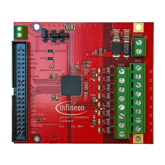
The Evaluation Board Revision 1.1 houses the ISOFACE™ ISO2H823V2.5 and a 40 pin header for an easy
Microcontroller or BUS-ASIC connection either per parallel or serial interface. At the process or factory side
different kind of loads can be connected at a 2 row 8 output terminal connector. The board is intended to
demonstrate the capabilities of the ISO2H823V2.5.
Internet Presence
http://www.infineon.com/isoface
Order Information
EVAL ISO2H823V2.5
Attention: The focus is safe operation under evaluation conditions. The board is neither cost nor size
optimized and does not serve as a reference design.
1
Overview . . . . . . . . . . . . . . . . . . . . . . . . . . . . . . . . . . . . . . . . . . . . . . . . . . . . . . . . . . . . . . . . . . . . . . 3
1.1
Board Overview . . . . . . . . . . . . . . . . . . . . . . . . . . . . . . . . . . . . . . . . . . . . . . . . . . . . . . . . . . . . . . . . . . . . . . . . . . . 4
2
Functional Description . . . . . . . . . . . . . . . . . . . . . . . . . . . . . . . . . . . . . . . . . . . . . . . . . . . . . . . . . . . 5
2.1
Power Supply . . . . . . . . . . . . . . . . . . . . . . . . . . . . . . . . . . . . . . . . . . . . . . . . . . . . . . . . . . . . . . . . . . . . . . . . . . . . . 5
2.2
Microcontroller Interface . . . . . . . . . . . . . . . . . . . . . . . . . . . . . . . . . . . . . . . . . . . . . . . . . . . . . . . . . . . . . . . . . . 5
2.2.1
Parallel Interface Mode . . . . . . . . . . . . . . . . . . . . . . . . . . . . . . . . . . . . . . . . . . . . . . . . . . . . . . . . . . . . . . . . . . 6
2.2.2
Serial Interface Mode . . . . . . . . . . . . . . . . . . . . . . . . . . . . . . . . . . . . . . . . . . . . . . . . . . . . . . . . . . . . . . . . . . . 10
2.3
Process Side . . . . . . . . . . . . . . . . . . . . . . . . . . . . . . . . . . . . . . . . . . . . . . . . . . . . . . . . . . . . . . . . . . . . . . . . . . . . . 12
2.3.1
Output Stage . . . . . . . . . . . . . . . . . . . . . . . . . . . . . . . . . . . . . . . . . . . . . . . . . . . . . . . . . . . . . . . . . . . . . . . . . . 12
3
Getting Started . . . . . . . . . . . . . . . . . . . . . . . . . . . . . . . . . . . . . . . . . . . . . . . . . . . . . . . . . . . . . . . . 16
3.1
Setting up the board for the parallel mode . . . . . . . . . . . . . . . . . . . . . . . . . . . . . . . . . . . . . . . . . . . . . . . . . 16
3.2
Setting up the board for the parallel direct mode . . . . . . . . . . . . . . . . . . . . . . . . . . . . . . . . . . . . . . . . . . . 17
3.3
Setting up the board for the serial mode . . . . . . . . . . . . . . . . . . . . . . . . . . . . . . . . . . . . . . . . . . . . . . . . . . . 18
4
Connectors . . . . . . . . . . . . . . . . . . . . . . . . . . . . . . . . . . . . . . . . . . . . . . . . . . . . . . . . . . . . . . . . . . . . 20
5
Production Data . . . . . . . . . . . . . . . . . . . . . . . . . . . . . . . . . . . . . . . . . . . . . . . . . . . . . . . . . . . . . . . 22
1
2015-02-11
Advertisement
Table of Contents

Related Manuals for Infineon ISOFACE ISO2H823V2


Summary of Contents for Infineon ISOFACE ISO2H823V2
-
Page 1: Table Of Contents
2 row 8 output terminal connector. The board is intended to demonstrate the capabilities of the ISO2H823V2.5. Internet Presence http://www.infineon.com/isoface Order Information EVAL ISO2H823V2.5 Attention: The focus is safe operation under evaluation conditions. The board is neither cost nor size optimized and does not serve as a reference design. - Page 2 ISO2H823V2.5 Evaluation Board Board Manual About this document Schematic ................22 Components Placement .
-
Page 3: Overview
CORE have to be buffered externally. The ISOFACE ISO2H823V2.5 includes 8 high-side power switches that are controlled by means of the integrated parallel/serial interface. The interface is 8-bit µController compatible. Furthermore a direct control mode can be selected that allows the direct control of the outputs OUT0 … OUT7 (power chip) by means of the inputs AD0 …... -
Page 4: Board Overview
ISO2H823V2.5 Evaluation Board Board Manual Overview Board Overview Figure 2 shows the main components of the ISO2H823V2.5 Evaluation Board and their interconnections. There are the following main building blocks: • ISO2H823V2.5 in a 12x12 mm PG-VQFN70-2 package • Supply connector 3V3 V •... -
Page 5: Functional Description
See Legal Disclaimer and Warnings for further restrictions on Infineon’s warranty and liability. Power Supply The Evaluation board can be powered on the connector X1 or via the connector SV1 with 3.3V. The process side can be powered via the 2 pin terminal X2 with 24V nominal. -
Page 6: Parallel Interface Mode
ISO2H823V2.5 Evaluation Board Board Manual Functional Description ODIS (Output Disable) The low active ODIS signal immediately switches off the output channels OUT0-OUT7. This pin has an internal Pull-Down resistor. In normal operation the signal ODIS is high. Setting ODIS to Low clears the DRIVE register as well. - Page 7 ISO2H823V2.5 Evaluation Board Board Manual Functional Description parallel _interface_iso2h823.vsd Figure 3 Bus Configuration for parallel mode Figure 4 Figure 5 The timing requirements for the parallel interface are shown in (Read), (Write) and inside the ISO2H823V2.5 chapter electrical characteristics in the datasheet.
- Page 8 ISO2H823V2.5 Evaluation Board Board Manual Functional Description WR_su ALE_high WRlow WRhigh WR_hd CS_ALE AD_su AD_hd AD_su AD_hd AD[7:0] DRIVE address (80h) DRIVE data (0Fh) DRIVE data (0Ah) DRIVE OUT[7:0] wr_timing_ifx - uc _parallel Figure 5 Timing by Parallel Write Access (e.g. DRIVE Register) For a writing access to internal registers the MSB of the address register has to be set to “1”.
- Page 9 ISO2H823V2.5 Evaluation Board Board Manual Functional Description 2.2.1.1 Parallel Direct Mode The parallel interface can be also used in a direct mode that allows direct changes of the output OUT0...OUT7 by means of the corresponding inputs AD0-AD7 without additional logic signals. To activate the parallel direct mode Figure 6 CS, WR and ALE pins have to be wired to ground and RD has to be wired to V as shown in the...
-
Page 10: Serial Interface Mode
ISO2H823V2.5 Evaluation Board Board Manual Functional Description 2.2.2 Serial Interface Mode ISO2H823V2.5 device contains a serial interface that can be activated by pulling the SEL pin to logic high state. The interface can be directly controlled by the µController output ports. The output pin SDO is in state “Z” as long as CS=1. - Page 11 ISO2H823V2.5 Evaluation Board Board Manual Functional Description SCLK B it15 B it8 B it7 B it 0 MS B LS B MS B LS B DR4 DR3 Channel-Values (Drive Information ) Checksum CD1 CD0 Collective Diagnosis Diagnosis / Checksum uc_spi_mode1.vsd Figure 9 SPI Mode 1, MS0 = 1, MS1 = 0, Daisy Chain Supported SCLK...
-
Page 12: Process Side
ISO2H823V2.5 Evaluation Board Board Manual Functional Description SCLK READ B it23 B it16 B it15 B it8 B it7 B it0 MS B LS B MS B LS B MS B LS B Register -Address (R/W) Value „Zero“ for CRC Checksum Read=0 Collective Diagnosis... - Page 13 ISO2H823V2.5 Evaluation Board Board Manual Functional Description The thermal hysteresis is reset during inactive mode. Therefore when switching to the active mode the power transistor is first switched on if the junction temperature is below 150°C. Current Sense and Limitation To achieve an excellent accuracy for the current limitation and current referred diagnostic (OCLx) an external reference resistor is used.
- Page 14 ISO2H823V2.5 Evaluation Board Board Manual Functional Description Monitoring GLERR Under Voltage Detection Missing Voltage Detection Reset Voltage Output Driver Control Unit Driver Protection Unit COLDIAG OUTx Zener Clamping (Demag. of Induct. Loads) Temperature Sensor IADJ Current Limitation Diagnostic Unit DIAGx Overload Detection Over Temperature Detection OLADJ...
- Page 15 ISO2H823V2.5 Evaluation Board Board Manual Functional Description 2.3.1.3 Power Supply The startup procedure of the power chip is explained in Figure 13. Voltage VBBuvoff VBBuvhys VBBuvon VBBmvoff VBBmvhys VBBmvon VBBon RESET VBBhys VBBoff Time por_uv_mv_events .vsd Figure 13 Start Up Procedure of the Power Chip During UVLO, all registers of the power chip are reset to their reset values as specified in the register description (Chapter 6 inside the datasheet).
-
Page 16: Getting Started
ISO2H823V2.5 Evaluation Board Board Manual Getting Started Getting Started In general to have a quick start, it is recommended either to use the parallel setup, serial mode 0 or serial mode 2. For a quick check of the switching perfomance the parallel direct mode will be the first choice. Setting up the board for the parallel mode Follow the steps before powering up the board •... -
Page 17: Setting Up The Board For The Parallel Direct Mode
ISO2H823V2.5 Evaluation Board Board Manual Getting Started Setting up the board for the parallel direct mode Follow the steps before powering up the board • Connect Jumper JP3 to GND (Connection 2-3). • Remove Jumper on JP1 and JP2, if present. •... -
Page 18: Setting Up The Board For The Serial Mode
ISO2H823V2.5 Evaluation Board Board Manual Getting Started Setting up the board for the serial mode Follow the steps before powering up the board • Connect Jumper JP3 to VCC (Connection 2-3). • Remove Jumper on JP1 and JP2, if you are planing to externally control the serial mode. •... - Page 19 ISO2H823V2.5 Evaluation Board Board Manual Getting Started Mode Selection Jumper Serial_Mode2.emf Figure 16 Jumper setting for serial mode 2 Application Note 2015-02-11 Revision 1.0...
-
Page 20: Connectors
ISO2H823V2.5 Evaluation Board Board Manual Connectors Connectors Connector SV1 !ODIS SYNC ALE / RST 10 n.c. n.c. n.c. n.c. n.c. !ERR MS0 / !RD 38 (Top View) Figure 17 Connector SV1 Signal Mapping Top View Application Note 2015-02-11 Revision 1.0... - Page 21 ISO2H823V2.5 Evaluation Board Board Manual Connectors Table 4 Connector SV1 Mapping per Mode Serial Mode Parallel Mode Comment ODIS ODIS SYNC SYNC CRCERR SCLK Table 5 Connector X3 Mapping Top Row Lower Row Comment OUT0 OUT1 OUT2 OUT3 OUT4 OUT5 OUT6 OUT7 Application Note...
-
Page 22: Production Data
ISO2H823V2.5 Evaluation Board Board Manual Production Data Production Data Schematic Figure 18 Schematic Application Note 2015-02-11 Revision 1.0... -
Page 23: Components Placement
ISO2H823V2.5 Evaluation Board Board Manual Production Data Components Placement Figure 19 Component Placement Application Note 2015-02-11 Revision 1.0... -
Page 24: Layout
ISO2H823V2.5 Evaluation Board Board Manual Production Data Layout Figure 20 Top Layer L1 Figure 21 Inner Layer L2 Application Note 2015-02-11 Revision 1.0... - Page 25 ISO2H823V2.5 Evaluation Board Board Manual Production Data Figure 22 Inner Layer L3 Figure 23 Bottom Layer L4 Application Note 2015-02-11 Revision 1.0...
-
Page 26: Bill Of Material
ISO2H823V2.5 Evaluation Board Board Manual Production Data Bill of Material The list of material is valid for the ISOFACE ISO2H823V2 Board V1.1 Revision July 2014. Table 6 Bill of Material Reference Value Device Package Designator C1, C3 1uF/ 16V C0805... - Page 27 Due to technical requirements, components may ANY DESCRIPTION OR WARRANTY OF A CERTAIN contain dangerous substances. For information on the © 2014 Infineon Technologies AG. FUNCTIONALITY, CONDITION OR QUALITY OF THE types in question, please contact the nearest Infineon All Rights Reserved. INFINEON TECHNOLOGIES COMPONENT.
- Page 28 Mouser Electronics Authorized Distributor Click to View Pricing, Inventory, Delivery & Lifecycle Information: Infineon EVALISO2H823V25TOBO1...
Need help?
Do you have a question about the ISOFACE ISO2H823V2 and is the answer not in the manual?
Questions and answers