Table of Contents
Advertisement
Quick Links
AN2016-19 Application Note
Control Integrated POwer System (CIPOS™)
3-Phase Interleaved PFC IPM (IFCMxxU65yz) Reference Board
About this document
Scope and Purpose
The scope of this application note is to describe the product reference board of the CIPOS™ Mini 3-phase
interleaved PFC IPM and the basic requirements for operating the product in a recommended mode.
Environmental conditions were considered in the design of the reference board. The design was tested as
described in this document but not qualified regarding safety requirements or manufacturing and operation
over the whole operating temperature range or lifetime. The boards provided by Infineon are subject to
functional testing only.
Reference boards are not subject to the same procedures as regular products regarding Returned Material
Analysis (RMA), Process Change notification (PCN) and Product Discontinuation (PD). Reference boards are
intended to be used under laboratory conditions by specialists only.
Intended Audience
Power electronics engineers who want to evaluate the CIPOS™ Mini 3-phase interleaved PFC IPM.
Table of Contents
1
Introduction .................................................................................................................. 3
2
Schematic ..................................................................................................................... 4
3
External Connection....................................................................................................... 5
3.1
Signal Connector ..................................................................................................................................... 5
3.2
Current Sensing Connector ..................................................................................................................... 5
3.3
ITRIP Connector....................................................................................................................................... 5
3.4
Power Terminals ..................................................................................................................................... 5
4
Key Parameters Setting .................................................................................................. 6
4.1
Circuit of Input Signals (LINx) ................................................................................................................. 6
4.2
Over Current Protection .......................................................................................................................... 6
4.2.1
Current Sensing Resistor Selection ................................................................................................... 7
4.2.2
Delay Time .......................................................................................................................................... 8
4.3
Temperature Monitor and Thermal Protection ..................................................................................... 9
5
Boost PFC Circuit Setting ............................................................................................... 11
5.1
Target Specification .............................................................................................................................. 11
5.2
Boost Inductor ....................................................................................................................................... 11
5.3
Output Capacitor ................................................................................................................................... 12
6
Part List ....................................................................................................................... 13
7
PCB Design Guide .......................................................................................................... 14
7.1
Layout of Reference Board.................................................................................................................... 14
8
Peripheral Components Connection................................................................................ 16
9
Evaluation Example of Reference Board .......................................................................... 17
9.1
Evaluation Results ................................................................................................................................. 17
AN2016-19 Application Note
www.infineon.com
Please read the Important Notice and Warnings at the end of this document
<Revision 2.0>
<2018-02-06>
Advertisement
Table of Contents

Related Manuals for Infineon CIPOS IFCMxxU65 Series


Summary of Contents for Infineon CIPOS IFCMxxU65 Series
-
Page 1: Table Of Contents
Environmental conditions were considered in the design of the reference board. The design was tested as described in this document but not qualified regarding safety requirements or manufacturing and operation over the whole operating temperature range or lifetime. The boards provided by Infineon are subject to functional testing only. - Page 2 Control Integrated POwer System (CIPOS™) 3-Phase Interleaved PFC IPM (IFCMxxU65yz) Reference Board Table of Contents Reference ........................18 AN2016-19 Application Note <Revision 2.0> <2018-02-06>...
-
Page 3: Introduction
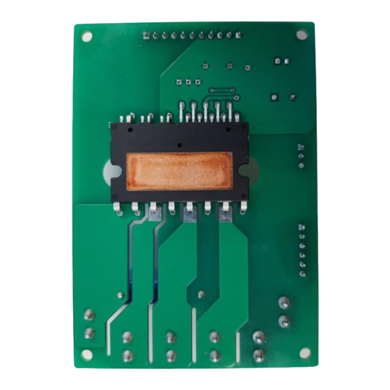
Control Integrated POwer System (CIPOS™) 3-Phase Interleaved PFC IPM (IFCMxxU65yz) Reference Board Introduction Introduction This reference board is composed of IFCM20U65GD, minimum peripheral components and three current sensing resistors. It is designed for customers to evaluate the performance of the CIPOS™ Mini 3-phase interleaved PFC IPM with simple connections of control signals and power wires. -
Page 4: Schematic
Control Integrated POwer System (CIPOS™) 3-Phase Interleaved PFC IPM (IFCMxxU65yz) Reference Board Schematic Schematic Figure 3 shows a circuitry of the reference board. The reference board consists of interface circuit, snubber capacitor, Over Current (OC) protection circuit, fault output circuit, current sensing resistors and passive parts etc. Figure 3 Circuit of the reference board Note: The “VDD5V”... -
Page 5: External Connection
Control Integrated POwer System (CIPOS™) 3-Phase Interleaved PFC IPM (IFCMxxU65yz) Reference Board External Connection External Connection Signal Connector Table 1 Pin description of the signal connector (CN1, 11-pin, 2.5mm pin pitch) Pin No. Name Description 1 ~ 3 No connection LIN(X) Control signal input for phase X IGBT LIN(Y) -
Page 6: Key Parameters Setting
Control Integrated POwer System (CIPOS™) 3-Phase Interleaved PFC IPM (IFCMxxU65yz) Reference Board Key Parameters Setting Key Parameters Setting Circuit of Input Signals (LINx) The input signals are compatible with either TTL or CMOS levels. The logic level can go down to 3.3V. The maximum input voltage of the input signal pin is clamped to 10.5V by the internal Zener diode. -
Page 7: Current Sensing Resistor Selection
Control Integrated POwer System (CIPOS™) 3-Phase Interleaved PFC IPM (IFCMxxU65yz) Reference Board Key Parameters Setting Figure 5 Timing chart of OC protection 4.2.1 Current Sensing Resistor Selection The value of the current sensing resistor can be calculated with the following equation. ... -
Page 8: Delay Time
Control Integrated POwer System (CIPOS™) 3-Phase Interleaved PFC IPM (IFCMxxU65yz) Reference Board Key Parameters Setting Based on the equation, condition and calculation method above, some example values of minimum current sensing resistance and required resistor power rating are introduced as shown in below Table 5 for CIPOS™ Mini 3-phase interleaved PFC IPM products. -
Page 9: Temperature Monitor And Thermal Protection
Control Integrated POwer System (CIPOS™) 3-Phase Interleaved PFC IPM (IFCMxxU65yz) Reference Board Key Parameters Setting Temperature Monitor and Thermal Protection In case of the CIPOS™ Mini 3-phase interleaved PFC IPM, a built-in thermistor (85kΩ at 25°C) is connected between NTC and VSS pins. The typical application circuit looks like Figure 6 where the NTC pin is used for thermistor temperature sensing and the VFO pin is used for fault flag. - Page 10 Control Integrated POwer System (CIPOS™) 3-Phase Interleaved PFC IPM (IFCMxxU65yz) Reference Board Key Parameters Setting Figure 7 Voltage variation of the NTC pin along with the NTC thermistor temperature change AN2016-19 Application Note <Revision 2.0> <2018-02-06>...
-
Page 11: Boost Pfc Circuit Setting
Control Integrated POwer System (CIPOS™) 3-Phase Interleaved PFC IPM (IFCMxxU65yz) Reference Board Boost PFC Circuit Setting Boost PFC Circuit Setting Target Specification Table 8 below shows a target specification example for the CIPOS™ Mini 3-phase interleaved PFC IPM reference board. Table 8 Design parameters for the proposed target specification Design parameter... -
Page 12: Output Capacitor
Control Integrated POwer System (CIPOS™) 3-Phase Interleaved PFC IPM (IFCMxxU65yz) Reference Board Boost PFC Circuit Setting The peak current passing through the inductor is, The on-duty of the transistor switch in a boost converter operating under CCM at minimum AC input RMS voltage is, The boost choke inductor value is, Calculating the equation above with the value of D... -
Page 13: Part List
11-pin connector for signal and power supply Yeonho SMW250-6P 6-pin connector for current sensing signal Yeonho SMW250-3P 3-pin connector for current sensing signal Yeonho J1 ~ J6 Fasten Tap Power terminals Infineon IFCM20U65GD CIPOS™ Mini 3-phase interleaved PFC IPM Technologies AN2016-19 Application Note <Revision 2.0> <2018-02-06>... -
Page 14: Pcb Design Guide
Control Integrated POwer System (CIPOS™) 3-Phase Interleaved PFC IPM (IFCMxxU65yz) Reference Board PCB Design Guide PCB Design Guide In general, there are several issues to be considered when designing a switching power supply application. Low stray inductive connection Isolation distance ... - Page 15 Control Integrated POwer System (CIPOS™) 3-Phase Interleaved PFC IPM (IFCMxxU65yz) Reference Board PCB Design Guide The connection between emitters of CIPOS™ Mini 3-phase interleaved PFC IPM (NX, NY and NZ) and current sensing resistors should be as short and as wide as possible. It is recommended that the ground pin of the micro-controller should be directly connected to the VSS pin.
-
Page 16: Peripheral Components Connection
Control Integrated POwer System (CIPOS™) 3-Phase Interleaved PFC IPM (IFCMxxU65yz) Reference Board Peripheral Components Connection Peripheral Components Connection This reference board is composed of IFCM20U65GD, minimum peripheral components and three current sensing resistors. So, in order to operate the reference board by 3-phase interleaved PFC topology, users need to set up additional external system and components such as bridge rectifier, boost inductor, main DC link capacitor, power supply, PFC control system, and resistive load. -
Page 17: Evaluation Example Of Reference Board
Control Integrated POwer System (CIPOS™) 3-Phase Interleaved PFC IPM (IFCMxxU65yz) Reference Board Evaluation Example of Reference Board Evaluation Example of Reference Board Evaluation Results Table 1 Evaluation Setup [DUT: IFCM20U65GD] Design parameter Parameter name Value Input voltage 220 [Vac] Line frequency 60 [Hz] Output voltage 400 [VDC]... - Page 18 3-Phase Interleaved PFC IPM (IFCMxxU65yz) Reference Board Reference Reference [1] Infineon Power Semitech: CIPOS™ IFCM20U65GD; Datasheet Ver1.0; Infineon Power Semitech, 2016 [2] Infineon Power Semitech: Design Guide for Boost Type CCM PFC with ICE2PCSxx, 2008 AN2016-19 Application Note <Revision 2.0> <2018-02-06>...
- Page 19 The data contained in this document is exclusively Email: erratum@infineon.com intended for technically trained staff. It is the Except as otherwise explicitly approved by Infineon responsibility of customer’s technical departments Technologies in a written document signed by Document reference to evaluate the suitability of the product for the...
Need help?
Do you have a question about the CIPOS IFCMxxU65 Series and is the answer not in the manual?
Questions and answers