Table of Contents
Advertisement
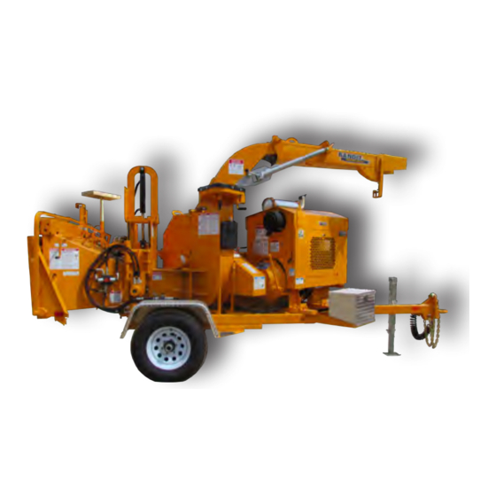
OPERATING & PARTS MANUAL
MODEL 200UC
Depending on what replacement parts you are ordering, we will need the following information:
MACHINE COMPONENTS
Serial Number
Model Number of Machine
MANUFACTURED BY BANDIT INDUSTRIES, INC
6750 MILLBROOK RD. • REMUS, MI 49340
PHONE:
989
561-2270
(
)
PHONE:
800
952-0178 IN USA
(
)
FAX:
989
561-2273 ~ SALES DEPT.
(
)
FAX:
989
561-2962 ~ PARTS/SERVICE
(
)
WEBSITE:
WWW.BANDITCHIPPERS.COM
Model No: __________________________
Serial No: __________________________
Engine Make: _______________________
Serial No: __________________________
Clutch Make: ________________________
Model: ___________ S/N _____________
DEALER:
Name: _____________________________
Address: ___________________________
City/State: __________________________
Phone No: __________________________
Delivery Date: _______________________
ATTENTION:
ENGINE COMPONENTS
Brand
Engine Serial Number
Engine Model Number
200UC
Copyright 1/21
CLUTCH COMPONENTS
Brand
Clutch Serial Number
Clutch Model Number
EMPLOYEE-OWNED
EMPLOYEE-OWNED
Advertisement
Table of Contents

Related Manuals for Bandit 200UC


Summary of Contents for Bandit 200UC
- Page 1 Serial Number Brand Brand Model Number of Machine Engine Serial Number Clutch Serial Number Engine Model Number Clutch Model Number MANUFACTURED BY BANDIT INDUSTRIES, INC 6750 MILLBROOK RD. • REMUS, MI 49340 PHONE: 561-2270 EMPLOYEE-OWNED EMPLOYEE-OWNED PHONE: 952-0178 IN USA FAX: 561-2273 ~ SALES DEPT.
- Page 2 CALIFORNIA PROPOSITION 65 WARNING Breathing diesel engine exhaust exposes you to chemicals known to the State of California to cause cancer and birth defects or other reproductive harm. • Always start and operate the engine in a well-ventilated area. • If in an enclosed area, vent the exhaust to the outside.
- Page 3 ACCIDENTS INVOLVING BRUSH CHIPPERS CAN AND SHOULD BE PREVENTED... Operator training and enforcement of safety policies are ESSENTIAL! Bandit Industries, Inc. Safety Booklet...
- Page 4 If you have purchased a Brush Bandit® Chipper second hand, know someone that has, or have resold a Brush Bandit® Chipper - please contact us. Please fax us at (989) 561-2273 or e-mail us at www. banditchippers.com with the chipper model number, chipper serial number, and current owners name, address, etc.
- Page 5 The following safety features have been developed for, and are currently being used on Brush Bandit® Chippers. They are available from your local Bandit® Dealer. Some are new and some have been presented before. We urge you to update your chippers with these devices.
- Page 6 Also supply the inside width dimension of the inlet end of the infeed hopper or existing 18” deep folding infeed pan. Folding infeed pans were optional on Bandit Chippers for many years. The 18” deep infeed pan became standard equipment on Bandit hand-fed chippers in February 1994.
- Page 7 The chipper hood must NEVER be opened, or pushed closed if the disc/drum is turning. When you supply the chipper model and serial number, this kit is available through your local Bandit® dealer. You also need to supply us with the engine make and model, then we will include the electric schematic to wire the device into the engine system.
- Page 8 Have you heard reports or seen your employees bending over and reaching into the infeed hopper, near the feedwheels? Along with the wooden push paddle and the infeed hopper tray, Bandit Industries, Inc. began installing on their mechanical feed hand fed chippers the patented “Last Chance Stop” cable system. This system has been standard on Bandit®...
- Page 9 FEED CONTROL BAR FEED CONTROL BAR R E V E R Brush Bandit® Chippers that are designed to be hand fed have F E E D a simple, easy to reach feed control bar located across the top and A R D F O R W down both sides of the infeed hopper.
- Page 10 Don’t slam the chipper hood open! It damages the hinge! The hinge needs periodic lubrication to properly operate and to avoid excessive wear! The hinge, hood rest, and hood require scheduled inspection. If they are damaged, replace them! Use only a Bandit factory replacement part.
- Page 11 Insert a small branch into the feedwheel(s). If the chips discharge properly, the chipper is clear and normal operation may resume. Bandit Industries, Inc. Safety Booklet viii...
- Page 12 Striped tape can be obtained through your local Bandit® dealer. The striped tape can be ordered by the foot under part number 900-9901-69.
- Page 13 When the need arises to replace a machine component with a decal attached, be sure and replace the decal. Replacement decals are available, and can be purchased from the manufacturer or your Bandit Dealer. Peel back about half of the backer paper on the decal. Position it on the flat, dry, clean surface so it is smooth and secure.
- Page 14 Training is essential! It is extremely important for everyone who operates a wood chipper to be trained. Operating instructions for the chipper are included in Bandit manuals, decals, and training videos with each chipper sold. We also highly recommend that you use the NAA chipper safety video.
- Page 15 11. _____ The customer has received instruction and fully understands that warranty will not apply if the machine is operated with replacement parts or equipment not manufactured or recommended by Bandit Industries, Inc. 12. _____ The customer has received, been advised, and understands the manuals, and the Safety/Service video supplied with the chipper.
- Page 16 Copyright 2-17 FORM #Q-111 DATE PURCHASE: ______________________ TO BE RETURNED AFTER THIRTY (30) DAYS OF OPERATION MODEL: ________________________________ SERIAL NUMBER: _______________________ Please return to: Customer Data Department 6750 Millbrook Road DEALER NAME: ________________________ Remus, MI 49340 _______________________________________ Phone: (800) 952-0178 in USA Phone: (989) 561-2270 Fax: (989) 561-2273...
-
Page 17: Table Of Contents
Chipper Assembly .....................72 Chipper Knife & Hardware ................74 Anvil & Hardware ....................75 Discharge Assemblies ................76 - 77 Hydraulics ....................78 - 85 Frame Assembly ....................86 Hyudraulic & Fuel Tank Assemblies ..............88 Optional Components ................90 - 94 Service Record ......................95 Bandit... - Page 19 WORK ORDER NUMBER LOCATIONS NOTICE 1. Serial Number on side of frame 2. Work Order Number on the side of tongue The engine information is located on the engine block. The clutch information is located on the clutch plate (if equipped). Bandit...
- Page 20 Improper use of the product can result in severe maintenance and repair of this BANDIT product. As personal injury. Personnel using the equipment must with any piece of equipment, safety should always...
-
Page 21: Safety Procedures
DANGER guidelines. If something is not fully understood, contact the nearest dealer or Bandit Industries for more training. Torn or loose clothing is more likely to get caught in moving machinery parts. Keep such items as long There must be at least two qualified and hair, shirt sleeves, and shirt tails properly contained. - Page 22 MODEL 200 UC SAFETY PROCEDURES SAFETY PROCEDURES DANGER Never sit, stand, lay, climb or ride anywhere on this Do not remove the hood pin until the chipper disc machine while it is running, operating, or in transit. has come to a complete stop. The chipper disc will You will be injured.
- Page 23 Failure to do this will cause serious injury. Bandit...
- Page 24 All nuts and bolts equipment unless specifically recommended or should be checked daily, especially the anvil and requested by Bandit Industries Inc. knife nuts and bolts for torque and fi t. This chipper is designed to be hand fed only. Do...
-
Page 25: Equipment Specifications
(Dimensions & weights will vary depending on optional equipment) Model 200 UC Length 198” (5.0 m) Width 68 1/2” (1.7 m) Height 94” (2.4 m) Weight 5200 lbs. (2360 kg) Fuel Capacity 24 1/2 Gal. Hydraulic Fluid Capacity 12 Gal. Bandit... -
Page 26: Machine Orientation Reference
MODEL 200 UC MACHINE ORIENTATION REFERENCE MACHINE ORIENTATION REFERENCE D I S D I A S I D I V E S I D I N F 1/21... - Page 27 Feedwheel control bar should pivot with little eff ort, by hand or with a pull on the “Last Chance” cables. Lubricate pivot points of the feedwheel control bar weekly. Adjust pivot tension with the tightness of inside friction nuts. Secure adjustment with outside jam nuts Bandit...
- Page 28 Discharge end, towards the end of the discharge Autofeed Controls On engine Engine Controls, Adjusters On engine 20 Electric Engine Throttle Adjuster On engine 21 “Bandit” Lever Throttle Adjuster On engine Knives & Hardware On chipper disc (not shown) 18,19,20,21 1/21...
- Page 29 In the event that dirty material is being run through the chipper the feedwheel trap door can be opened. Bandit...
- Page 30 MODEL 200 UC OPERATION CHIPPER HOOD ENGINE DISABLE PLUG This chipper hood engine disable plug is installed NOTICE for safety purposes. It is designed to shut down the The engine disable plug has a circuit fuse. If engine if the hood pin is not properly in place holding the engine will not start or run, check the fuse fi rst the chipper hood in the closed position.
- Page 31 Check the fuel level daily, running out and repriming is time consuming. Do The Bandit throttle system has (2) positions, HIGH not over fi ll the tank, there must be expansion space and LOW. Engine R.P.M. is controlled by moving the in the top of the tank.
-
Page 32: Operation
If something is not fully understood, contact the nearest dealer or Bandit Industries for more training. Never feed any materials that might contain wires, stones, nails, metal objects, or any foreign... - Page 33 Figure 1 Travel Path Turn away from the infeed hopper and keep moving after releasing the limb or log. Release limb or log into chipper Butt end of Travel brush fi rst Path Bandit...
- Page 34 MODEL 200 UC OPERATION MACHINE OPERATION NOTICE A wooden push paddle has been provided to Chippers are not designed to cut chunk wood, assist in feeding smaller material. It is the owner’s dimensional lumber including rail road ties, or end and operator’s responsibility to use and keep a cut logs standing on end.
- Page 35 You can purchase sure the ignition key is in your possession, install the disc lock pin, and disconnect the battery. additional Bandit manuals, decals and videos for a nominal fee. BELT TENSIONER ENGAGED NOTICE...
- Page 36 MODEL 200 UC OPERATION OPTIONAL HYDRAULIC BUMP BAR OPERATION • The optional Hydraulic Bump Bar comes set from DANGER the factory and is non adjustable. The hydraulic bump bar is an optional device • If the Hydraulic Bump Bar is pushed, the which may help prevent accidents.
-
Page 37: Transportation Procedures
Machine must be hauled level and the towing 10. Check tires for correct pressure, abnormal vehicle must be sized to handle hitch weight, towing wear, cuts or damaged rims. weight, and braking requirements. Bandit... - Page 38 MODEL 200 UC TRANSPORTATION PROCEDURES OPTIONAL SLIDING TONGUE The optional sliding tongue is used when the chipper’s tongue is not long enough to hook to the machine to a tow vehicle and have proper clearance when turning or backing up the machine. 1.
-
Page 39: Maintenance
Expensive damage to the machine will occur if and has been properly trained. You can purchase proper preparation is not taken before welding on additional Bandit manuals, decals and videos for a the machine. Be sure to disconnect both battery nominal fee. - Page 40 MODEL 200 UC MAINTENANCE MAINTENANCE How often to check Procedure Daily Weekly Monthly Quarterly Yearly What to Check ü Page # (10 hrs.) (50 hrs.) (200 hrs.) (500 hrs.) (2000 hrs.) Safety procedures reviewed Anvil clearance, 36 - 37 tightness & wear Alternator &...
- Page 41 Check the fan blades, anvil, and a ttaching of the failures related to bearings are diagnosed hardware for the knives and anvil. Replace if as “Contamination”. Contamination is caused by necessary. improper lubrication. Wipe off excess grease. Excessive grease will attract dirt. Bandit...
- Page 42 CHECK & OIL FEEDWHEEL SLIDE BOX tension adjustment, frequently adjust and lubricate Check that the feedwheel slide box is working per PTO clutch manufacturer’s manual. Bandit smoothly and oil with 10W/30 type motor oil. Clean Industries, Inc. does not warranty clutch failures.
- Page 43 3 months or 400 hours. HYDRAULIC SUCTION SCREEN(S) DISCHARGE SWIVEL PLATES Change hydraulic suction screen(s) yearly or Grease swivel plates for discharge as needed. every 2000 hours. FUEL TANK Drain and clean the fuel tank yearly. Bandit...
- Page 44 MAINTENANCE WHAT TO CHECK RESULTS ITEM Sharp knives - Bandit approved new Proper sharpening procedures will pay knives or professionally sharpened dividends! Maintaining your chipper knives will reduce fuel consumption and Proper knife width and angle increase the life of your chipper.
- Page 45 See if they are stuck or full of debris Belts may slip and glaze over that will Refer to the autofeed manual for not be covered under warranty. troubleshooting and the owners manual for additional troubleshooting and information on settings. Bandit...
- Page 46 (Brass) Each knife installed in every new machine at Bandit V I L has the Knife Saver used on it before leaving the Remove brass bar after building up area with hard surface weld factory.
- Page 47 Only Bandit approved knives and hardware are Chipper knives must be kept sharp at all times for recommended for use in your Bandit chippers. Only the ultimate chipper and knife performance. The main then can you be assured of a quality product that fi ts cause of poor cutting performance is dull knives.
- Page 48 Only Bandit approved knives and hardware are recommended for use in your Bandit chippers. Only then can you be assured of a quality product that fits and performs the best to the standards of excellence that is expected from the Bandit chipper.
- Page 49 It is always necessary for your protection to be cracks. If a problem is found, contact your nearest extra careful and wear proper hand protection when dealer or Bandit Industries, Inc. handling knives. Make sure to check both knife pockets.
- Page 50 Use a feeler to 1.6 mm). gauge or the anvil to knife gauge supplied by Bandit 5. Set the closest knife to this distance. to check the clearance of the first knife to the anvil.
- Page 51 View looking from the curb side of the throat area machine at the anvil area Anvil Anvil Anvil Adjuster Knife Bolt Anvil Bolts Torque To Specs Anvil To Anvil Puller Anvil Anvil Adjuster Disc Knife Gauge Block Handle Bolt Bandit...
- Page 52 MODEL 200 UC MAINTENANCE UNPLUGGING THE CHIPPER DANGER If the chipper is properly maintained and operated If the discharge or hood need to be removed, correctly, the chipper should not plug. In the unlikely always use some sort of mechanical device like an event that the chipper becomes plugged, do not overhead hoist, loader, lift truck, etc.
- Page 53 Adjust or Action particular parallel Characteristic and balance particular stops and replace load per to the needed of wide tires. Adjust or load per adjust tire catalog ground fl otation tires replace. tire catalog brakes Bandit...
- Page 54 MODEL 200 UC MAINTENANCE BELT TENSION SAFETY INSTRUCTIONS NOTICE Before attempting any type of maintenance, DO NOT IGNORE THIS MAINTENANCE RULE disengage clutch, wait for the disc to come to a complete New belts stretch very soon and must be adjusted stop, turn off engine, remove the ignition key, make several times in the fi rst few hours of operation.
- Page 55 Pump Drive Belts: 1/4” (6.4 mm) deflection with needed adjustment or replacement. 9 lbs. (4.1 kg) of force. GOOD BELT WORN SHEAVE WORN BELT BELT BELT BELT SPACE SHEAVE SHEAVE SHEAVE Bandit...
- Page 56 MODEL 200 UC MAINTENANCE CLUTCHLESS BELT TENSION SAFETY INSTRUCTIONS NOTICE Before attempting any type of maintenance, Every month, the beltshield needs to be removed disengage clutch, wait for the disc to come to a complete and the belts need to be checked and adjusted. stop, turn off engine, remove the ignition key, make Without starting the engine, it is a good practice to sure the ignition key is in your possession, install the...
- Page 57 ENGINE SHEAVE CHIPPER BELT SHEAVE KEEPER BOTTOM BELTSHIELD MUST HAVE A CLEARANCE OF 1/4” - 3/8” FIGURE 3 Straight Edge Belt tensioner must be parallel with the engine sheave and the chipper sheave CHIPPER BELT ENGINE SHEAVE TENSIONER SHEAVE Bandit...
- Page 58 Do not spend excessive time trying to remove the pin and coupler. If problems occur during pin and coupler removal, contact your nearest dealer or Bandit Industries. 1/21...
- Page 59 MAINTENANCE SERVICING / CHANGING FEEDWHEEL BEARING WITH THE GRIP TIGHT BEARING BEHIND FEEDWHEEL MOTOR Your Bandit Chipper may be equipped with a The machine is set up with one set screw bearing tapered lock style (Grip Tight) feedwheel bearing and one Grip Tight bearing because the one Grip...
- Page 60 50 lbs. (22.7 kg) check for binding of any parts, worn hydraulic valve, or any obstructions. If the required force can not be obtained contact your local dealer or Bandit Industries Inc. NOTICE The hydraulic bump bar valve may trip at diff erent forces, depending on the temperature of the hydraulic fl uid.
- Page 61 8. Crank the jack to lower the yoke and top wheel so the weight is on the yoke lock pin and not the jack. 9. Block and chain the top wheel up before doing any work inside throat 10. After the maintenance is complete, reverse the steps before putting the chipper back to work. Slide Box Style Yoke Pivot Style Yoke Bandit...
- Page 62 MODEL 200 UC MAINTENANCE MAINTENANCE EASY CLIMB FEED SYSTEM ADJUST ACCORDINGLY AS SPRINGS STRETCH SAFETY INSTRUCTIONS MOUNT Before attempting any type of maintenance, disengage clutch, wait for the disc to come to a complete POSITION 4 stop, turn off engine, remove the ignition key, make YOKE sure the ignition key is in your possession, install the disc lock pin, and disconnect the battery.
- Page 63 PAINT & DECAL CARE PAINT CARE DECAL CARE To help keep up the appearance of your Bandit Decals located on your Bandit equipment contain equipment and reduce the possibility of surface rust useful information to assist you in operating your follow these steps: equipment safely.
-
Page 64: Hydraulics
MODEL 200 UC HYDRAULICS HYDRAULICS WARNING SAFETY INSTRUCTIONS Before attempting any type of maintenance, Do not operate this machine unless all hydraulic disengage clutch, wait for the disc to come to a complete control devices operate properly. They must function, stop, turn off engine, remove the ignition key, make shift and position smoothly and accurately at all sure the ignition key is in your possession, install the... -
Page 65: Hydraulic Fluid Requirements
Based on the varying temperatures of the area When choosing a hydraulic fl uid ‑ these maximum where Bandit equipment is used, and the high and minimum specifi cations must be met: demand and loads placed on this equipment,... - Page 66 MODEL 200 UC HYDRAULICS HYDRAULICS TYPICAL HYDRAULIC RELIEF PRESSURE SETTINGS TYPICAL HYDRAULIC FLOWS AND RPM SETTINGS (Approximate, For Reference Only, Engine At Full RPM) NOTICE Do not under any circumstances over-set these After the initial start-up of the machine and after relief pressures, it will cause damage to component any replacement of hydraulic components, fittings parts and hydraulic parts.
- Page 67 HEX HEAD PLUG: Remove to access the relief valve with a 5/8” wrench. MAINTAIN FEEDWHEEL HYDRAULIC PRESSURE AT SPECIFIED PSI (bar) Follow typical hydraulic flow and relief settings on page 52 Follow proper hydraulic oil requirements on page 51 Bandit...
- Page 68 MODEL 200 UC HYDRAULICS HYDRAULIC PRESSURE ADJUSTMENT NO PRESSURE CHECK KIT SAFETY INSTRUCTIONS With the engine shut down, make sure the hydraulic oil is clean and the tank is 7/8 full. Start the engine to allow the hydraulic oil to warm up. Before checking or adjusting the hydraulic pressure settings, make sure the engine is shut off and the ignition key is in your possession.
- Page 69 6. Pressure gauge should read maximum specified readjusted as needed once a month for best PSI (bar). performance. ONLY CLOSE BALL VALVE FOR 4-5 SECONDS TO SET PRESSURE OR YOU MAY DAMAGE HYDRAULICS. MAINTAIN FEEDWHEEL HYDRAULIC PRESSURE AT SPECIFIED PSI (bar). Bandit...
-
Page 70: Hydraulic Pressure Settings
MODEL 200 UC HYDRAULICS HYDRAULIC PRESSURE ADJUSTMENT OPTIONAL COMPONENTS SAFETY INSTRUCTIONS NOTICE Before attempting any hydraulic pressure settings, All optional components may be checked this way. make sure engine is shut off , engine key removed and in your possession, hydraulic oil is clean, hydraulic tank is 7/8 full, and the machine has been pre-run to warm the hydraulic oil. -
Page 71: Control Valve
Place the end of the hose in a clean 5 gallon with Live Hydraulics, for machines without Live (19L) pail. Hydraulics contact your local dealer or Bandit Plug the open port of the control valve or main Industries. relief valve. - Page 72 MODEL 200 UC HYDRAULICS CORRECTING HYDRAULIC PROBLEMS HYDRAULIC PUMP CHECK OUT HYDRAULIC PUMP CHECK WITHOUT USING A FLOW METER To check out the hydraulic pump the mechanic will need a needle type control valve, a pressure gauge capable of reading 5000 psi (344 bar), an in-line 2500 psi (172 bar) relief, and a hose long enough to span between the pump and the hydraulic tank.
- Page 73 Flow Meter (with relief) Hose supplied by First you. component after pump. Flow Direction Outlet Do not exceed Pump 90% of system pressure. Flow Hydraulic Direction Tank Bandit...
-
Page 74: Detent Assembly
MODEL 200 UC HYDRAULICS CONTROL VALVE DETENT ASSEMBLY AND O-RING REPLACEMENT Tools Required: - Small amount of clean hydraulic oil 3/4” Drag Link - Clean working area, free of debris and shop rags Drive Socket - 3/16” Tee handle hex driver - 3/4”... - Page 75 Feedwheels do not Engine not at correct high RPM Raise the engine RPM come on Flow control turned down Turn back up Bad detent in feed valve Replace detent assembly Bandit...
-
Page 76: Electrical
MODEL 200 UC ELECTRICAL TYPICAL ELECTRICAL WIRING DIAGRAMS WIRING FOR STANDARD 6 PRONG PLUG AND 6 WIRE MAIN CABLE POWER TO BREAKAWAY - BLACK WIRE BREAKAWAY SWITCH 6 Wire Main Cable Color Code Red R (Brakes & Breakaway Switch) White W (Ground) RIGHT TURN-GREEN WIRE Green G (Right Turn) LEFT TURN-YELLOW WIRE... -
Page 77: Replacement Parts
Engine Serial Number machine. Engine Spec. Number Bandit Industries Inc. reserves the right to make CLUTCH COMPONENTS changes in models, size, design, installations and Brand applications on any part without notification. -
Page 78: Decals
MODEL 200 UC REPLACEMENT PARTS DECALS Decal locations may vary, these are general locations. 2,18 7,19, 56,57 34,35 50,51,55,58,59 12,21 25,26 27,49,60 24,31,38,39, 6,10,16 40,53,55 2,18 14,30,43 11,19 34,35 20,21 2 8,41,42, 15,17,21 44,48 1/21... - Page 79 (Red/White) Grease Axle Torsion Arm 64 900-8900-32 Basic Safety Decal Kit INST-199 Bushing... Bandit Model 200 UC Logo 65 900-8901-91 Decal Kit NOTICE Optional equipment may require additional decals. Some decals are for optional equipment. Decal locations may vary, these are general locations. If any decals become damaged, replace immediately.
- Page 80 MODEL 200 UC REPLACEMENT PARTS 35” INFEED HOPPER MODELS 200UC TAIL LIGHT ASSEMBLY (PRE 4/16) 1/21...
-
Page 81: Infeed Assembly
Pivot Pin - Drive Side 980-200177 Tail Light Mount - Radiator Side 986-2001-09 Feed Control Bar (Start 9/16) 39 900-2923-53 LED Tail Light 986-3003-33 Feed Control Bar (4/16 - 9/16) 40 980-2002-82 Heavy Duty Tail Light Cover 980-300186 Feed Control Bar (Pre 4/16) Bandit... - Page 82 MODEL 200 UC REPLACEMENT PARTS 45” INFEED HOPPER MODELS 200UC TAIL LIGHT ASSEMBLY (PRE 4/16) 1/21...
- Page 83 Pivot Pin - Drive Side 980-200177 Tail Light Mount - Radiator Side 905-2001-56 Feed Control Bar (Start 9/16) 39 900-2923-53 LED Tail Light 905-2001-12 Feed Control Bar (4/16 - 9/16) 40 980-2002-82 Heavy Duty Tail Light Cover 980-300187 Feed Control Bar (Pre 4/16) Bandit...
- Page 84 MODEL 200 UC REPLACEMENT PARTS YOKE ASSEMBLY 1/21...
- Page 85 980-100137 Feedwheel Slide Box Assembly Lift Feedwheel Slide Box 980-200114 Weldment NOTICE The top feedwheel bearing bolts need to be ground Grip-Tite style feedwheel bearings are on the off flush with inside of yoke, if replaced. hydraulic motor side. Bandit...
-
Page 86: Chipper Assembly
MODEL 200 UC REPLACEMENT PARTS CHIPPER ASSEMBLY 1/21... - Page 87 18NF High Hex Nut 980-300413 Auto Clutch Fan Blade Assembly 40 980-2004-59 Beltshield Assembly ** Components vary with engine options order by physical description or machine S/N. *-* Contact your nearest dealer or Bandit Industries for Fan Blade Assemblies. Bandit...
-
Page 88: Chipper Knife & Hardware
MODEL 200 UC REPLACEMENT PARTS CHIPPER KNIFE & HARDWARE Part Number Description 1/2” x 4” x 7 1/4” Chipper Knife 900-9902-00 (Start 9/12) 3/8” x 4” x 7 1/4” Chipper Knife 900-9900-02 (Pre 5/12) Chipper Knife Bolt - 900-4901-53 1/2”-13NC x 2 1/2” Chipper Knife Nut - 900-4900-27 1/2”-13NC... -
Page 89: Anvil & Hardware
5/16”-18NC Hex Nut (Includes 2 - 12) 900-4902-58 Anvil Washer Anvil & Hardware Kit 14 980-0507-77 900-4906-86 1/2” Lock Washer (Includes 1 - 12) 1/2”-13NC x 1 1/2” Hex Head 900-4906-72 Bolt Anvil Bolt Torque: 75 ft.-lbs. (102 Nm) Bandit... -
Page 90: Discharge Assemblies
MODEL 200 UC REPLACEMENT PARTS MANUAL DISCHARGE Part Number Description Part Number Description 980-3013-58 Bottom Swivel Ring 001-3004-19 Discharge Flipper Hinge 980-300349 Hood Flange 12” Discharge Flipper 980-200077 Assembly Discharge Transport Bolt - 900-4911-04 5/8”-11NC x 1 1/2” 12” Enclosed Discharge Flipper 980-0510-25 Assembly Discharge Transport Nut - 5/8”-... - Page 91 20 980-300349 Hood Flange 980-0510-25 Assembly Discharge Transport Bolt - 5/8”- Discharge Flipper Adjusting 900-4911-04 900-4901-83 11NC x 1 1/2” Spring Discharge Transport Nut - 5/8”- 900-4907-04 900-7900-93 Black Rubber Cap 11NC Adjusting Spring Lock Plate 980-2005-30 Assembly for Flipper Bandit...
- Page 92 MODEL 200 UC REPLACEMENT PARTS IN-LINE HYDRAULIC PRESSURE CHECK KIT Part Number Description Part Number Description 900-3920-73 5000 PSI Gauge 900-3926-11 Ball Valve 900-3902-24 Quick Coupler 900-3922-14 Fitting - Hose 900-3902-23 Test Nipple In-Line Pressure Check Kit 980-100121 (Includes 1 - 7) 900-3911-47 Rubber Cap for Test Nipple 900-3924-86...
-
Page 93: Hydraulics
* Hydraulic components, fittings, hoses will vary depending on optional equipment. Order by physical description. ** Hydraulic pumps need to be ordered by physical description and serial number of machine. NOTICE Make sure to order components according to fitting type, fittings may vary on all components. Bandit... - Page 94 MODEL 200 UC REPLACEMENT PARTS HYDRAULIC SCHEMATIC (Pre 12/17) JIC / SAE PIPE O-RING FITTING Examples of straight fittings. Part Number Description Part Number Description See Pages See Page 78 In-Line Pressure Check Kit Hydraulic Tank 88 - 89 7 900-3920-05A Feedwheel Control Valve 900-3901-41 Hydraulic Tank Strainer...
- Page 95 900-3984-25 Subplate Torque Retainer Nut to a maximum of 4 to 6 ft.-lbs. (5 to 8 Nm) and install Loctite 243. Over torque will cause damage and will also void warranty. ** Refer to check sheet for Autofeed Harness. Bandit...
- Page 96 MODEL 200 UC REPLACEMENT PARTS “AUTOFEED PLUS” VALVE (DUAL SOLENOID) Part Number Description 900-3981-51 Retainer Nut & Sealing Ring 900-2909-55 Herschman Connector Only 900-3983-37 Solenoid Only 900-3982-41 Dual Solenoid Assembly 900-3975-31 Autofeed Plus Subplate 900-3978-26 Seal Kit for Valve Autofeed Harness “AUTOFEED PLUS”...
- Page 97 Main Relief Only 500-0000-77 Dump Block Assembly w/ Relief Torque Autofeed Cartridge Nut to a maximum of 4 to 6 ft.-lbs. (5 to 8 Nm) and install Loctite 243. Over torque will cause damage and will also void warranty. Bandit...
- Page 98 MODEL 200 UC REPLACEMENT PARTS HOSE CLAMP HOSE GUARD Part Number Description 900-3934-76 Hose Guard - 4” Long 900-3934-77 Hose Guard - 6” Long 900-3934-78 Hose Guard - 8” Long FLOW DIVIDER Part Number Description Bolt Locking Plate for 1/2” Double 900-3914-11 Clamp Plastic Clamp for 1/2”...
- Page 99 Master Link Only 14 904-0003-35 Valve Spool Spring 904-0003-31 Pin & Cotter Key 15 904-0003-36 Valve Spacer 904-0003-32 Bracket, Handle & Chain Link 900-A-2941 Spring Center Kit 900-3937-34 Seal Kit Detent Cap with Screws for 17 904-0003-37 Spring Loaded Valve Bandit...
-
Page 100: Frame Assembly
MODEL 200 UC REPLACEMENT PARTS FRAME ASSEMBLY OPTIONAL SLIDING TONGUE 1/21... - Page 101 Optional Safety Marker for 17 980-200204 Tool Box Tray 35 900-5904-52 Fenders 900-7900-78 Optional Aluminum Tool Box 36 900-7900-48 Optional Mud Flap 980-0508-37 Optional Steel Tool Box 37 900-9904-94 Optional Vice Optional Radiator Guard Post 19 980-0508-61 38 980-300113 Vice Mount Assembly Bandit...
- Page 102 MODEL 200 UC REPLACEMENT PARTS HYDRAULIC & FUEL TANK ASSEMBLY LOCKABLE FILLER CAP (Pre 1/18) HEAVY DUTY LOCKABLE FILLER CAP (Pre 1/18) 1/21...
- Page 103 900-3926-82 3/8” NPTF to 3/8” Hose Barb 900-3931-53 3/8” NPTF to 5/16” Hose Barb NOTICE Components vary with fuel type. Specify gas or Tank assemblies vary with options. Specify all diesel when ordering fuel tank components. options when ordering. Bandit...
- Page 104 MODEL 200 UC REPLACEMENT PARTS HYDRAULIC BUMP BAR Version 2 1/21...
- Page 105 Bump Bar Valve Linkage Override Switch 900-3956-75 Bump Bar Valve 14 900-3988-24 Momentary Override Valve 915-3002-17 Bump Bar Valve Cover Momentary Override Push 900-2903-07 900-4906-54 3/8”-16NC x 3/4” Bolt Button Switch 900-4906-84 1/2”-13NC Lock Nut 999-8001-88 Momentary Override Timer Bandit...
- Page 106 MODEL 200 UC REPLACEMENT PARTS HYDRAULIC BUMP BAR 1/21...
- Page 107 Hydraulic Bump Bar Assembly 917-2000-19 13 900-3956-26 Momentary Override Valve - 54” Infeed Push Plate for Momentary Hydraulic Bump Bar Assembly 14 905-3002-14 911-2000-99 Override Switch - 64” Infeed Momentary Override Push 900-2903-07 Button Switch 999-8001-88 Momentary Override Timer Bandit...
- Page 108 MODEL 200 UC REPLACEMENT PARTS CLUTCHLESS ASSEMBLY Part Number Description Part Number Description 800-2000-26 Clutchless System Mount 12 900-1925-09 Tensioner Arm 800-2000-20 Clutchless Engagement Handle 13 900-1925-23 Tensioner 800-3000-85 Pivot Side Plate 14 800-3001-04 Idler Spacer Bushing 900-1924-14 Flange Bushing 15 800-3001-14 Idler Spacer 800-2000-28...
-
Page 109: Service Record
MODEL 200 UC SERVICE RECORD SERVICE RECORD DATE DESCRIPTION AMOUNT Bandit... - Page 110 MODEL 200 UC SERVICE RECORD SERVICE RECORD DATE DESCRIPTION AMOUNT 1/21...
Need help?
Do you have a question about the 200UC and is the answer not in the manual?
Questions and answers