Table of Contents
Advertisement
Quick Links
Advertisement
Table of Contents

Related Manuals for NEXIQ Technologies USB-Link


Summary of Contents for NEXIQ Technologies USB-Link
- Page 1 USB-Link ™ Installation and Setup Manual...
- Page 2 IDSC Holdings LLC. You may not decipher or decompile USB-Link software, develop source code for the USB-Link, or knowingly allow others to do so. The USB-Link and its documentation may not be sublicensed or transferred without the prior written consent of IDSC Holdings LLC.
- Page 3 Safety Information For your safety, read this manual thoroughly before operating your USB-Link™ unit. Your USB-Link™ unit is intended for use by properly trained, skilled professional heavy- duty technicians. The safety messages presented below and throughout this user’s manual are reminders to the operator to exercise extreme care when using this test instrument.
-
Page 4: Important Safety Instructions
Risk of electric shock. • Do not exceed voltage limits between inputs as indicated on the rating label. • Use extreme caution when working with circuits that have greater than 60 volts DC or 25 volts AC. USB-Link™ Installation and Setup Manual... - Page 5 • If vehicle has an automatic parking brake release, disconnect release mechanism for testing and reconnect when finished. • Do not leave a running engine unattended. A moving vehicle can cause injury. Save These Instructions USB-Link™ Installation and Setup Manual...
- Page 6 Safety Information USB-Link™ Installation and Setup Manual...
-
Page 7: Table Of Contents
Installation and Bluetooth Configuration ....9 Installation Process Flowchart ..........10 Outline of Installation Process ..........11 Step 1: Install the USB-Link™ Drivers and Utilities ....12 Instructions for Windows® 2000 and XP Users ......12 Instructions for Vista® Users ............22 USB-Link™ Installation and Setup Manual... - Page 8 Configure the Bluetooth Environment .........52 Chapter 3: Preparing to Use the USB-Link™ ......55 Step 5: Connect the USB-Link™ to a Vehicle ......56 Wireless Connection ................57 Wired Connection Using a USB Cable ..........58 Step 6: Use the Bluetooth Connection Utility ......60 Step 7: Test the Connection to the Vehicle .........65...
- Page 9 Chapter 4: USB-Link™ Troubleshooting Information ....73 LED Issues ..................74 Configuration Issues ..............75 Wireless Communication Issues ..........76 Appendix A: Warranty and Service .......... 77 Exclusive Warranty ..............78 Exclusive Remedy ...............79 Return Materials Authorization (RMA) .........80 Return of Goods Policy ..............82 Return Goods Authorization (RGA) Procedure ......83...
- Page 10 USB-Link™ Installation and Setup Manual...
-
Page 11: Introducing The Usb-Link
System Requirements, page 3 USB-Link™ Components, page 4 Communication Options: Wireless or Wired?, page 5 he USB-Link™ is a hardware device that enables service bay personal computers ® (PCs) to retrieve vehicle information using either Bluetooth wireless technology or a more traditional cable connection. -
Page 12: Product Specifications
Chapter • Introducing the USB-Link™ Product Specifications The USB-Link™ is configured with the following specifications: Feature Data Physical Dimensions 5.86" x 3.02" x 1.78" (149 mm x 77 mm x 45 mm) Weight 4.6 oz. (0.13 kg) Power Requirements 10 - 32 VDC @ 350 mA maximum Operating Temperature 0 to +70 °C... -
Page 13: System Requirements
Vista Bluetooth adapter • Bluetooth serial port capability ® • Must support WIDCOMM drivers, 1.4x and higher The USB-Link™ has been qualified with the following Class 1 adapters: - Linksys USBBT100 (preferred) - Belkin F8T001 USB-Link™ Installation and Setup Manual... -
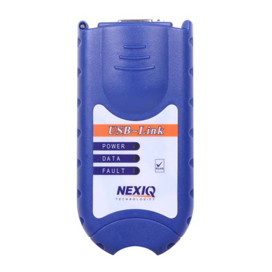
Page 14: Usb-Link™ Components
Chapter • Introducing the USB-Link™ USB-Link™ Components The following illustration details each of the USB-Link™ components: Figure 1.1 USB-Link™ Components a chapter’s first page. The page’s layout isements (e.g., ChapIntro, Body Text, Bullets, etc.), not headings. Headings on this page produce alignment If the introduction paragraphs a chapter’s first page. -
Page 15: Communication Options: Wireless Or Wired
- Communication Options: Wireless or Wired? Communication Options: Wireless or Wired? Prior to using the USB-Link™, you need to decide how you want the unit to com- municate with your PC. There are two options: • Wireless connection to the PC using Bluetooth A wireless connection provides the advantage of untethered communication. -
Page 16: Wireless Connection
• Run the NEXIQ Bluetooth Connection Utility — For information on running the NEXIQ Bluetooth Connection Utility, refer to Chapter 3: Preparing to Use the USB-Link™, later in this manual. — USB-Link™ is intended for diagnostic use, for example, retrieving trouble codes. -
Page 17: Wired Connection
USB, which can result in dropped messages in situations requiring high band- width. ECU reprogramming typically requires both high throughput and critical timing, and should always use a USB-to-PC wired connection. Wired communication between the USB-Link™ and your PC requires a USB cable. Figure 1.4 15 ft. - Page 18 Chapter • Introducing the USB-Link™ USB-Link™ Installation and Setup Manual...
-
Page 19: Installation And Bluetooth Configuration
Installation and Bluetooth Configuration Step 1: Install the USB-Link™ Drivers and Utilities, page 12 Instructions for Windows® 2000 and XP Users, page 12 Instructions for Vista® Users, page 22 Step 2: Choose Your Connection, page 33 Step 3: Install the Bluetooth Adapter, page 35... -
Page 20: Installation Process Flowchart
Update BT Drivers Environm ent C onnect to Vehicle Connect to Vehicle (Physical) (P hysical) Run C onnect Utility Test the C onnection S et U p Diagnostic A pplications Figure 2.1 Process Flowchart 10 USB-Link™ Installation and Setup Manual... -
Page 21: Outline Of Installation Process
Bluetooth environment. Step 5: Connect the USB-Link™ to the vehicle. Step 6: Use the NEXIQ Bluetooth Connection Utility to select a USB-Link™ and test the signal strength. Step 7: Use the NEXIQ Device Tester to test the connection between the USB- Link™... -
Page 22: Step 1: Install The Usb-Link™ Drivers And Utilities
, please refer to the special instructions for Vista users on page 22 of this manual. Prior to using the USB-Link™ it is necessary to install the required NEXIQ device drivers and utilities on your PC or laptop. These device drivers are ®... - Page 23 - Step 1: Install the USB-Link™ Drivers and Utilities The installation begins by displaying the Welcome! screen. Figure 2.2 Installation Welcome! Screen —If the program does not automatically start, access your CD-ROM drive through My Computer and double-click the SETUP.EXE file.
- Page 24 Chapter • Installation and Bluetooth Configuration The Copyright Notice screen is displayed. Figure 2.3 Copyright Notice Screen Read all the information on this screen, then click I Accept. 14 USB-Link™ Installation and Setup Manual...
- Page 25 - Step 1: Install the USB-Link™ Drivers and Utilities NOTE: If you do not agree to the terms, click I Decline . A message is displayed prompting you to confirm exiting the installation. Click EXIT SETUP . The Backup Replaced Files? screen is displayed.
- Page 26 At the bottom of the screen, select the desired drive letter from the drop- down list. Double-click each directory to add to the path. Click OK to proceed. The program returns to the Select Backup Directory screen. Confirm the destination, then click Next. 16 USB-Link™ Installation and Setup Manual...
- Page 27 - Step 1: Install the USB-Link™ Drivers and Utilities The Select Components screen is displayed. Figure 2.6 Select Components screen Check the check box to install J2534 support for HINO Diagnostic eXplorer. Click Next to continue. USB-Link™ Installation and Setup Manual...
- Page 28 Wait for the Ready to Install! screen to appear. Figure 2.7 Ready to Install! Screen NOTE: Be sure to disconnect all RP1210A adapters currently connected to the PC before proceeding with the installation. Do one of the following: 18 USB-Link™ Installation and Setup Manual...
- Page 29 - Step 1: Install the USB-Link™ Drivers and Utilities —Click Next to proceed with the installation. —Click Back to step backward through previous screens. —Click Cancel to stop the installation. A dialog box displaying a status bar is displayed indicating percentage complete.
- Page 30 NOTE: ® The Adobe Acrobat Reader is required to view this Installation Manual electronically as a portable document format (PDF) file. ® If, however, your PC requires installation of the Adobe Acrobat Reader, the 20 USB-Link™ Installation and Setup Manual...
- Page 31 - Step 1: Install the USB-Link™ Drivers and Utilities following screen is displayed. Figure 2.11 Acrobat Reader Installation Screen Click Next to accept the default (Yes), and follow the prompts. Wait for the Installation Completed! screen to appear, then click Finish.
-
Page 32: Instructions For Vista® Users
Move on to “Step 2: Choose Your Connection,” later in this chapter. ® Instructions for Vista Users Prior to using the USB-Link™ it is necessary to install the required NEXIQ device drivers and utilities on your PC or laptop. These device drivers are compatible with ® ®... - Page 33 - Step 1: Install the USB-Link™ Drivers and Utilities The AutoPlay window opens. Click Install or run program (i.e., “Run setup.exe Published by IDSC Holdings LLC”). Click Continue. The installation begins by displaying the Welcome! screen. Figure 2.14 Installation Welcome! Screen —If the program does not automatically start, access your CD-ROM drive...
- Page 34 Chapter • Installation and Bluetooth Configuration The Copyright Notice screen is displayed. Figure 2.15 Copyright Notice Screen Read all the information on this screen, then click I Accept. 24 USB-Link™ Installation and Setup Manual...
- Page 35 - Step 1: Install the USB-Link™ Drivers and Utilities NOTE: If you do not agree to the terms, click I Decline. A message is displayed prompting you to confirm exiting the installation. Click EXIT SETUP. The Backup Replaced Files? screen is displayed.
- Page 36 At the bottom of the screen, select the desired drive letter from the drop- down list. Double-click each directory to add to the path. Click OK to proceed. The program returns to the Select Backup Directory screen. Confirm the destination, then click Next. 26 USB-Link™ Installation and Setup Manual...
- Page 37 - Step 1: Install the USB-Link™ Drivers and Utilities The Select Components screen is displayed. Figure 2.18 Select Components screen Check the check box to install J2534 support for HINO Diagnostic eXplorer. Click Next to continue. USB-Link™ Installation and Setup Manual...
- Page 38 Wait for the Ready to Install! screen to appear. Figure 2.19 Ready to Install! Screen NOTE: Be sure to disconnect all RP1210A adapters currently connected to the PC before proceeding with the installation. Do one of the following: 28 USB-Link™ Installation and Setup Manual...
- Page 39 - Step 1: Install the USB-Link™ Drivers and Utilities —Click Next to proceed with the installation. —Click Back to step backward through previous screens. —Click Cancel to stop the installation. A Windows Security warning is displayed. Figure 2.20 Windows Security Warning Click on the check box labeled Always trust software from “Jungo LTD”.
- Page 40 Chapter • Installation and Bluetooth Configuration Windows Security displays the following window: Figure 2.22 Windows Security Warning Click Install this driver software anyway. Wait while the drivers are installed. 30 USB-Link™ Installation and Setup Manual...
- Page 41 - Step 1: Install the USB-Link™ Drivers and Utilities The following dialog is displayed: Figure 2.23 Acrobat Reader Search Dialog ® If your PC requires installation of the Adobe Acrobat Reader, the following screen is displayed. Figure 2.24 Acrobat Reader Installation Screen Click Next to accept the default (Yes), and follow the prompts.
- Page 42 Figure 2.26 Restart Prompt Click OK to restart the PC. Once the PC restarts, remove the installation CD from the CD-ROM or DVD- ROM drive. Move on to “Choose Your Connection,” next in this manual. 32 USB-Link™ Installation and Setup Manual...
-
Page 43: Step 2: Choose Your Connection
- Step 2: Choose Your Connection Step 2: Choose Your Connection You have two options for connecting the USB-Link™ to a PC or laptop computer. Choose one of the following options. Both have advantages. • Wired connection using a 15 ft. USB cable The advantage of a wired connection is faster throughput (e.g., you want... - Page 44 • Plug in the Bluetooth adapter (i.e., the dongle) • Insert the USB Bluetooth Adapter CD into your PC’s CD-ROM drive • Install the necessary Bluetooth drivers. Move on to “Install the Bluetooth Adapter” next in this manual. 34 USB-Link™ Installation and Setup Manual...
-
Page 45: Step 3: Install The Bluetooth Adapter
- Step 3: Install the Bluetooth Adapter Step 3: Install the Bluetooth Adapter The USB-Link™ has been qualified with the following Class 1 (100 m range) Blue- tooth USB Adapters. Class 1 adapters are recommended because of their greater operating range. -
Page 46: Step 4: Install The Bluetooth Drivers
The Linksys Welcome screen is displayed. Figure 2.29 Bluetooth Linksys USB Adapter Welcome screen IMPORTANT: ä Ignore the instruction on the screen, “To function properly...” Click the Install button to install the Linksys USB Bluetooth software. 36 USB-Link™ Installation and Setup Manual... - Page 47 - Step 4: Install the Bluetooth Drivers The Welcome to the InstallShield Wizard screen is displayed. Figure 2.30 InstallShield Wizard Welcome screen Click Next, and follow the on-screen prompts. The License Agreement screen is displayed. USB-Link™ Installation and Setup Manual...
- Page 48 Chapter • Installation and Bluetooth Configuration Figure 2.31 License Agreement screen Click the I accept the terms in the license agreement button. Click Next to continue. 38 USB-Link™ Installation and Setup Manual...
- Page 49 - Step 4: Install the Bluetooth Drivers Figure 2.32 Destination Folder screen Click Next to install the folder. USB-Link™ Installation and Setup Manual...
- Page 50 • Installation and Bluetooth Configuration The Ready to Install the Program screen is displayed. Figure 2.33 Ready to Install the Program screen Click Install to begin the installation. Wait while the InstallShield Wizard installs the Linksys Bluetooth software. 40 USB-Link™ Installation and Setup Manual...
- Page 51 The process may take several minutes. The Driver Signature Notice is displayed. Figure 2.34 Driver Signature Notice screen Click OK to avoid display of multiple prompts for signed drivers during the remainder of the installation. USB-Link™ Installation and Setup Manual...
- Page 52 The Linksys Bluetooth USB Adapter Welcome screen is displayed (Fig. 2.15). Click the Exit button, and remove the CD from the CD-ROM drive. Restart your system so that the changes you made can take effect. 42 USB-Link™ Installation and Setup Manual...
- Page 53 (see “Step 3: Install the Bluetooth Adapter”), you do not need to perform the last two procedures in this chapter. Move on to “Step 5: Connect the USB-Link™ to a Vehicle” in Chapter 3. However, if you are installing another adapter (e.g., the Belkin adapter) or you failed to install the adapter as instructed (pg.
-
Page 54: Additional Steps For Windows Xp Sp-2
Bluetooth Adapter icon will have changed from red to white (see Figure 2.44). To update the Bluetooth drivers: From the Windows desktop, right-click My Computer and select Properties Hardware Device Manager. 44 USB-Link™ Installation and Setup Manual... - Page 55 Typically, you will see two items in the folder, one for the Bluetooth Adapter you installed earlier in this guide and one for Microsoft Bluetooth Enumera- tor (see Figure 2.37, above). Right-click the Belkin Bluetooth Adapter item. Do not click on the Microsoft Bluetooth Enumerator. USB-Link™ Installation and Setup Manual...
- Page 56 Chapter • Installation and Bluetooth Configuration The following menu is displayed. Figure 2.38 Bluetooth Adapter Menu Choose Update Driver... from the menu. 46 USB-Link™ Installation and Setup Manual...
- Page 57 Wizard), and click Next to continue. Figure 2.39 The Hardware Update Wizard May or May Not Appear. If the above screen does not appear, move on to step 5, next in this proce- dure (see Figure 2.40). USB-Link™ Installation and Setup Manual...
- Page 58 The Hardware Update Wizard is displayed. Figure 2.40 Hardware Update Wizard Ignore the on-screen prompt “If your hardware came with an installation CD...,” and select Install from a list or specific location (Advanced). Click Next. 48 USB-Link™ Installation and Setup Manual...
- Page 59 - Additional Steps for Windows XP SP-2 The Please choose your search and installation options screen is displayed. Figure 2.41 Choose Your Search and Installation Options. Select ( ) Don’t search. I will choose the driver to install. Click Next. USB-Link™ Installation and Setup Manual...
- Page 60 Have Disk button. From the Model area of the screen, select the device driver that is not digitally signed (i.e., the device driver without the icon next to it). Click Next. 50 USB-Link™ Installation and Setup Manual...
- Page 61 In addition, the Windows taskbar has been updated. Note that the Microsoft Bluetooth Enumerator icon no longer appears (compare Figure 2.44 with Figure 2.36). Figure 2.44 Updated Windows Taskbar Move on to “Configure the Bluetooth Environment,” next in this manual. USB-Link™ Installation and Setup Manual...
-
Page 62: Configure The Bluetooth Environment
NOTE: If the Configuration Wizard does not start up, double-click the My Blue- tooth Places shortcut on the Windows desktop. Figure 2.45 Initial Bluetooth Configuration Wizard To configure a basic Bluetooth environment: Click Next. 52 USB-Link™ Installation and Setup Manual... - Page 63 Clear all of the check boxes except the Bluetooth Serial Port check box. NOTE: You need to use the scroll bar on the right side of the screen to view all of the check boxes. Click Next. USB-Link™ Installation and Setup Manual...
- Page 64 Skip to Continue Without Configuring Another Device Click Skip. The Initial Bluetooth Configuration Wizard Congratulations screen is displayed. Click Finish, and move on to Chapter 3, Preparing to Use the USB-Link™, next in this manual. 54 USB-Link™ Installation and Setup Manual...
-
Page 65: Preparing To Use The Usb-Link
Step 7: Test the Connection to the Vehicle, page 65 Step 8: Setting Up Diagnostic PC Applications, page 68 his chapter provides instructions for connecting the USB-Link™ to a vehicle, using the Bluetooth Connection Utility, and testing the connection. It also includes instructions on setting up the diagnostic personal computer (PC) applications supported by the USB- Link™. -
Page 66: Step 5: Connect The Usb-Link™ To A Vehicle
Chapter • Preparing to Use the USB-Link™ Step 5: Connect the USB-Link™ to a Vehicle The USB-Link™ interfaces with the vehicle by means of any one of the following connectors: • 6-pin Deutsch • 9-pin Deutsch • 9-pin Deutsch - 1 meter •... -
Page 67: Wireless Connection
- Step 5: Connect the USB-Link™ to a Vehicle NOTE: For additional information on choosing the right connector for your situa- tion, refer to Adapter Guide for the USB-Link™ (NEXIQ Part No. 1400- 357). The following illustration shows how the USB-Link™ connects with the vehicle:... -
Page 68: Wired Connection Using A Usb Cable
PC running an RP1210A compliant application connects and disconnects from the USB-Link™. In addition, when the USB-Link™ is out of range (more than 100 ft.) of the PC while the application is running, the device will beep and the fault LED will flash until the USB-Link™... - Page 69 - Step 5: Connect the USB-Link™ to a Vehicle Connect the other end of the cable to the port on the device as shown in the following illustration: Figure 3.2 Connecting to a Notebook Computer Using a USB Cable Connect the DB15 male end of the appropriate adapter cable to the USB- Link™.
-
Page 70: Step 6: Use The Bluetooth Connection Utility
Chapter • Preparing to Use the USB-Link™ Step 6: Use the Bluetooth Connection Utility You use the Bluetooth Connection Utility to do the following: • Select an adapter • Open a serial connection to the adapter • Test that the adapter is online and ready to respond •... - Page 71 Select a Bluetooth Adapter —A list of vehicle adapters on the network is displayed in the data window. From the Vehicle Adapters available from all devices: list, select the vehicle adapter to which you want to connect. USB-Link™ Installation and Setup Manual...
- Page 72 Chapter • Preparing to Use the USB-Link™ The following screen is displayed. Figure 3.6 Adapter Selection Click OK to confirm the selection. 62 USB-Link™ Installation and Setup Manual...
- Page 73 —If the Test Signal Strength: status bar (located in the lower left corner) in- dicates that the signal is low, you can move the USB-Link™ closer to the PC/laptop and click Optimize Signal Strength.
- Page 74 Chapter • Preparing to Use the USB-Link™ lf-second intervals until you click on the Stop Signal Adjustment button. NOTE: ® The Optimize Signal Strength button is only available with Widcomm Bluetooth PC Driver version 1.4x and higher. Figure 3.8 Optimize Signal Strength Once the test is complete, the results of the operation are displayed in the lower right corner of the screen.
-
Page 75: Step 7: Test The Connection To The Vehicle
- Step 7: Test the Connection to the Vehicle Step 7: Test the Connection to the Vehicle You use the Device Tester to test the connection between the USB-Link™ and the vehicle. At startup, the Device Tester checks for any NEXIQ drivers installed on the PC. - Page 76 If the Connection Indicator button is red (i.e., Not Connected), do one of the following: —For wireless connection using Bluetooth technology: • In the Device list, make sure that the heading is BT USB-Link (Protocol desired). • Check to ensure that the connections between the USB-Link™...
- Page 77 - Step 7: Test the Connection to the Vehicle —For wired connection using a USB cable: • In the Device list, make sure that the heading is USB-Link (Pro- tocol desired). • Check to ensure that the connections between the USB-Link™...
-
Page 78: Step 8: Setting Up Diagnostic Pc Applications
Protocol field, then select J1939. Click on the next to the Device field, then select USB-Link J1939 if con- nection is wired; select BT USB-Link J1939 if the connection is wireless. Connect Click Allison DOC™ for Fleets (3000/4000) -
Page 79: Bendix Abs Diagnostics
Click on the next to the Protocol field, then select J1708. Click on the next to the Device field, then select USB-Link J1708 if the con- nection is wired; select BT USB-Link J1708 is the connection is wireless. Connect Click... -
Page 80: Cummins Insite
Click on the radio button ( ) for RP1210A . The screen prompts you to select an RP1210A adapter type. Select USB-Link, for the protocol that you wish to use (i.e., J1708 or J1939). 70 USB-Link™ Installation and Setup Manual... -
Page 81: Detroit Diesel Diagnostic Link
From the PC’s desktop, click Detroit Die- Options Next> Click Select the Local Communication Interface by clicking on the arrow of the drop- down list and pointing to the appropriate protocol (i.e., USB-Link J1708 or BT USB-Link J1708). Next> Click Finish Click... -
Page 82: International Intune
Click on the System Setup menu item, then select COM Port. The Device Settings screen appears. Under Vendor, click on the drop-down list box, then select NEXIQ (NNT, Inc.) USB-Link Under Device, click on the drop-down list box, then select USB-Link J1708. Click OK. 72 USB-Link™ Installation and Setup Manual... -
Page 83: Usb-Link™ Troubleshooting Information
Wireless Communication Issues, page 76 his chapter provides troubleshooting information to assist you in resolving issues that may arise when setting up and using the USB-Link™. NOTE: If you have questions about using this product, contact NEXIQ Technical Support at (800) 639-6774, or send us an e-mail at support@nexiq.com. -
Page 84: Led Issues
Chapter • USB-Link™ Troubleshooting Information LED Issues The following table provides some possible causes and solutions to issues related to the USB-Link’s light-emitting diodes (LEDs). Problem Possible Cause Solution Power LED on the Loose or faulty Check to make certain USB-Link™... -
Page 85: Configuration Issues
- Configuration Issues Configuration Issues The following table provides some possible causes and solutions to issues that may be experienced when configuring the USB-Link™ and/or PC for wireless communication. Problem Possible Solution Cause PC applications Not set up for Under the application that produce communi- USB-Link™. -
Page 86: Wireless Communication Issues
Chapter • USB-Link™ Troubleshooting Information Wireless Communication Issues The following table lists some possible causes and solutions to issues that may be experienced when attempting to set up the USB-Link™ to use wireless communication. Problem Possible Solution Cause Unable to find Blue-... -
Page 87: Warranty And Service
Service Exclusive Warranty, page 78 Exclusive Remedy, page 79 Return Materials Authorization (RMA), page 80 Return of Goods Policy, page 82 Return Goods Authorization (RGA) Procedure, page 83 his appendix provides warranty and service information. USB-Link™ Installation and Setup Manual... -
Page 88: Exclusive Warranty
• Warranty and Service Exclusive Warranty The USB-Link™ adapter is warranted for a period of one (1) year from the date of purchase to be free of defects in materials and workmanship and to be merchant- able and fit for its intended purpose. -
Page 89: Exclusive Remedy
NEXIQ Technologies or, at the option of NEXIQ Technologies, refund of the purchase price. This is the exclusive remedy. -
Page 90: Return Materials Authorization (Rma)
Auburn Hills, MI 48326 Attention: Product Service/Repair Department During the warranty period, NEXIQ Technologies will, at its option, repair or replace the product which proves to be defective or refund the purchase price. Customers MUST obtain an RMA number before repair items are sent in for service. - Page 91 (This is for non-warranty and rework charges.) The customer is responsible for shipping and handling charges on non-warranty repairs and non-warranty rework. With all warranty repairs, NEXIQ is responsible for the shipping costs of the return to customer. USB-Link™ Installation and Setup Manual...
-
Page 92: Return Of Goods Policy
Any damaged or missing parts will be deducted from the final credit total. NO RETURNS ARE ACCEPTED WITHOUT AN RGA (RETURN GOODS AUTHORIZATION) NUMBER. Customers are responsible for return shipping charges. 82 USB-Link™ Installation and Setup Manual... -
Page 93: Return Goods Authorization (Rga) Procedure
Return the unit(s) to NEXIQ Location at: NEXIQ Technologies 2329 East Walton Auburn Hills, MI 48326 Attention: Returns/Quality Control Department Local: 1-248-232-6610 USB-Link™ Installation and Setup Manual... - Page 94 Chapter • Warranty and Service Toll Free: 1-800-639-6774 NOTE: The customer is responsible for return shipping and handling to NEXIQ. 84 USB-Link™ Installation and Setup Manual...
Need help?
Do you have a question about the USB-Link and is the answer not in the manual?
Questions and answers