Table of Contents
Advertisement
Advertisement
Table of Contents

Related Manuals for NEXIQ Technologies USB-Link

Summary of Contents for NEXIQ Technologies USB-Link
- Page 1 USB-Link™ Installation and Setup Manual...
- Page 2 IDSC Holdings LLC. You may not decipher or de-compile USB-Link, develop source code for USB-Link, or knowingly allow others to do so. USB-Link and its documentation may not be sublicensed or transferred without the prior written consent of IDSC Holdings LLC.
-
Page 3: Table Of Contents
Chapter 2: Installation and Bluetooth Configuration ....9 Installation Process Flowchart .............10 Outline of Installation Process .............11 Step 1: Install the USB-Link™ Drivers and Utilities .....12 Step 2: Choose Your Connection ..........20 Wired Connection ................20 Wireless Connection ................21 Step 3: Install the Bluetooth Drivers ..........22 Instructions for Windows XP Users ............ - Page 4 Chapter 4: USB-Link™ Troubleshooting Information ....73 LED Issues ..................74 Configuration Issues ..............76 Wireless Communication Issues ..........76 Appendix A: USB-Link™ Adapter and Cable Guide ....77 Choosing the Right Cable Adapter ..........78 Adapter Drawings ................79 USB-Link™ Installation and Setup Manual...
-
Page 5: Product Specifications
USB-Link™ Components, page 4 Communication Options: Wireless or Wired?, page 5 he USB-Link™ is a hardware device that enables service bay personal computers ® (PCs) to retrieve vehicle information using either wireless Bluetooth technology or a more traditional cable connection. Once configured, the USB-Link™ interfaces with your PC, enabling you to use specific PC applications to perform vehicle diagnostics. -
Page 6: Introducing The Usb-Link
Chapter • Introducing the USB-Link™ Product Specifications The USB-Link™ is configured with the following specifications: Feature Data Physical Dimensions 5.86" x 3.02" x 1.78" (149 mm x 77 mm x 45 mm) Weight 4.6 oz. (0.13 kg) Power Requirements 10 - 32 VDC @ 350 mA maximum Operating Temperature 0 to +70 °C... -
Page 7: System Requirements
® • Bluetooth serial port capability Bluetooth adapter ® • Must support WIDCOMM drivers, 1.4x and (sold separately) higher The USB-Link™ has been qualified with the follow- ing Class 1 adapter: ® - IOGEAR GBU321 USB-Link™ Installation and Setup Manual... -
Page 8: Usb-Link™ Components
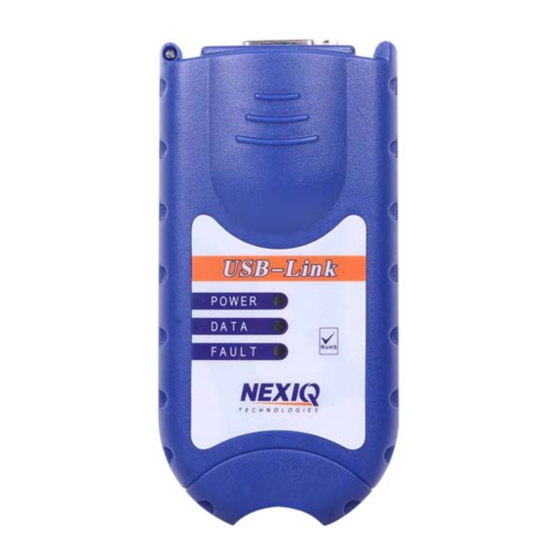
Chapter • Introducing the USB-Link™ USB-Link™ Components The following illustration details each of the USB-Link™ components: Figure 1.1 USB-Link™ Components USB-Link™ Installation and Setup Manual... -
Page 9: Communication Options: Wireless Or Wired
- Communication Options: Wireless or Wired? Communication Options: Wireless or Wired? Prior to using the USB-Link™, you need to decide how you want the unit to communicate with your PC. There are two options: ® • Wireless connection to the PC using Buletooth (pg. - Page 10 Chapter • Introducing the USB-Link™ If your PC does not have Integrated Bluetooth, then you are clear to proceed with the USB-Link™ installation process as documented in this manual: ® • Install Bluetooth drivers ® • Install an external Bluetooth...
-
Page 11: Wired Connection
USB, which can result in dropped messages in situations requiring high bandwidth. ECU reprogramming typically requires both high throughput and critical timing, and should always use a USB-to-PC wired connection. Wired communication between the USB-Link™ and your PC requires a USB cable. Figure 1.4 15 ft. -
Page 12: Installation And Bluetooth Configuration
Installation and Bluetooth Configuration Step 1: Install the USB-Link™ Drivers and Utilities, pg. 12 Step 2: Choose Your Connection, pg. 20 Step 3: Install the Bluetooth Drivers, pg. 22 Instructions for Windows XP Users, pg. 22 ... -
Page 13: Installation Process Flowchart
Chapter • Installation and Bluetooth Configuration Installation Process Flowchart Figure 2.1 Process Flowchart 10 USB-Link™ Installation and Setup Manual... -
Page 14: Outline Of Installation Process
- Outline of Installation Process Outline of Installation Process Step 1: Install the NEXIQ™ USB-Link™ drivers and utilities (pg. 12). Step 2: Choose your connection (wired or wireless) (pg. 20). If you chose a wired connection, move on to complete steps 4, 6, and 7 only. -
Page 15: Step 1: Install The Usb-Link™ Drivers And Utilities
• Installation and Bluetooth Configuration Step 1: Install the USB-Link™ Drivers and Utilities Prior to using the USB-Link™ it is necessary to install the required NEXIQ™ device drivers and utilities on your PC or laptop. These device drivers are compat- ®... - Page 16 - Step 1: Install the USB-Link™ Drivers and Utilities If the program does not automatically start, access your CD-ROM drive through My Computer and double-click the SETUP.EXE file. Read the information displayed on the Welcome! screen, and click Next. The Copyright Notice screen is displayed.
- Page 17 Do one of the following: —Click Yes if you wish to back up copies of files replaced during the instal- lation (recommended). —Click No if you do not wish to back up files. Click Next to continue. 14 USB-Link™ Installation and Setup Manual...
- Page 18 - Step 1: Install the USB-Link™ Drivers and Utilities If you chose to back up replaced files, the installation program requests a location to store the files. Figure 2.5 Select Backup Directory Screen Do one of the following: —To accept the default directory, click Next and proceed to Step 7 (recommended).
- Page 19 Be sure to disconnect all RP1210A adapters currently connected to the PC before proceeding with the installation. Do one of the following: —Click Next to proceed with the installation. —Click Back to step backward through previous screens. —Click Cancel to stop the installation. 16 USB-Link™ Installation and Setup Manual...
- Page 20 - Step 1: Install the USB-Link™ Drivers and Utilities A dialog box displaying a status bar is displayed indicating percentage complete. Figure 2.7 Status Bar ® If Microsoft .NET Framework is not found on your PC, the following dialog box is displayed.
- Page 21 If you are running Windows XP, move on to Step 11 (pg. 19). Figure 2.9 Windows 7 Security Message Click Install to continue. Figure 2.10 Windows 7 Security Message Click Install this driver software anyway. 18 USB-Link™ Installation and Setup Manual...
- Page 22 - Step 1: Install the USB-Link™ Drivers and Utilities Wait for the Installation Completed! screen to appear. Figure 2.11 Installation Completed! Screen Click Finish. A message appears prompting you to restart the PC. Figure 2.12 Restart Prompt Click OK to restart the PC.
-
Page 23: Step 2: Choose Your Connection
Chapter • Installation and Bluetooth Configuration Step 2: Choose Your Connection You have two options for connecting the USB-Link™ to a PC or laptop computer. • Wired connection using a 15 ft. USB cable ® • Wireless connection using Bluetooth Choose one of the following options. -
Page 24: Wireless Connection
• Install the necessary Bluetooth drivers. ® • Plug the Bluetooth adapter (i.e., the dongle) into an available USB port on your laptop. Move on to “Step 3: Install the Bluetooth Drivers” next in this manual. USB-Link™ Installation and Setup Manual... -
Page 25: Step 3: Install The Bluetooth Drivers
Chapter • Installation and Bluetooth Configuration Step 3: Install the Bluetooth Drivers The USB-Link™ has been qualified with the following Class 1 (100 m range) Blue- ® tooth USB adapter: © • IOGEAR GBU321 Class 1 adapters are recommended because of their greater operating range. - Page 26 - Step 3: Install the Bluetooth Drivers Figure 2.16 Preparing to install...Status Message The Welcome to the InstallShield Wizard screen is displayed Figure 2.17 InstallShield Wizard Welcome Screen Click Next, and follow the on-screen prompts. USB-Link™ Installation and Setup Manual...
- Page 27 Chapter • Installation and Bluetooth Configuration The License Agreement screen is displayed. Figure 2.18 License Agreement screen Click the I accept the terms in the license agreement button. Click Next to continue. 24 USB-Link™ Installation and Setup Manual...
- Page 28 - Step 3: Install the Bluetooth Drivers The Destination Folder screen is displayed. Figure 2.19 Destination Folder Screen Click Next to install the folder. USB-Link™ Installation and Setup Manual...
- Page 29 Click Install to begin the installation. Figure 2.21 Wait while the InstallShield Wizard installs the software. A status bar provides an indication of how close the wizard is to completing the installation. The process may take several minutes. 26 USB-Link™ Installation and Setup Manual...
- Page 30 Bluetooth device not found Message Plug the IOGEAR Bluetooth adapter into an available USB port on your laptop, and wait while the wizard installs the adapter. Figure 2.23 InstallShield Wizard Completed Screen Click Finish to exit the wizard. USB-Link™ Installation and Setup Manual...
- Page 31 • Installation and Bluetooth Configuration Remove the installation CD from the CD-ROM drive. Move on to “Step 4: Connect the USB-Link™ to a Vehicle” in Chapter 3. NOTE: If you have installed the IOGEAR Bluetooth adapter, you do not need to perform the last two procedures in this chapter.
-
Page 32: Instructions For Windows 7 Users
When the installation is complete, the following message is displayed: Your device is ready to use. Move on to “Step 4: Connect the USB-Link™ to a Vehicle” in Chapter 3. NOTE: If you have installed the IOGEAR Bluetooth adapter, you do not need to perform the last two procedures in this chapter. -
Page 33: Configure The Bluetooth Environment
You do not need to perform this procedure if you have installed the ® IOGEAR Bluetooth adapter. Instead, move on to “Step 4: Connect the USB-Link™ to a Vehicle” in Chapter 3 of this manual. ® Once you have installed the Bluetooth adapter, the Initial Bluetooth Configu- ration Wizard is displayed. - Page 34 Clear all of the check boxes except the Bluetooth Serial Port check box. NOTE: You need to use the scroll bar on the right side of the screen to view all of the check boxes. Click Next. USB-Link™ Installation and Setup Manual...
- Page 35 Skip to Continue Without Configuring Another Device Click Skip. The Initial Bluetooth Configuration Wizard Congratulations screen is displayed. Click Finish. Move on to Chapter 3, Preparing to Use the USB-Link™, next in this manual. 32 USB-Link™ Installation and Setup Manual...
-
Page 36: Preparing To Use The Usb-Link
Step 7: Setting Up Diagnostic PC Applications, page 51 his chapter provides instructions for connecting the USB-Link™ to a vehicle, pairing the device, and testing the connection. It also includes instructions on setting up the diag- nostic personal computer (PC) applications supported by the USB-Link™. -
Page 37: Step 4: Connect The Usb-Link™ To A Vehicle
Chapter • Preparing to Use the USB-Link™ Step 4: Connect the USB-Link™ to a Vehicle The USB-Link™ interfaces with the vehicle by means of any one of the following connectors: • 6-pin Deutsch • 9-pin Deutsch • 9-pin Deutsch - 1 meter •... -
Page 38: Making The Connection
36) Wired Connection Using a USB Cable To connect the USB-Link™ to a PC or laptop using a USB cable: Connect the USB cable to the USB port of the PC or laptop. Connect the other end of the cable to the port on the device as shown in the following illustration: Figure 3.2... -
Page 39: Wireless Connection
PC running an RP1210A or RP1210B compliant application connects and discon- nects from the USB-Link™. In addition, when the USB-Link™ is out of range (more than 100 ft.) of the PC while the application is running, the device will beep and the fault LED will flash until the USB-Link™... -
Page 40: Step 5: Pair The Device
To use the Connect Utility: From the taskbar on the Windows desktop, right-click the Bluetooth Connect Utility icon. The Bluetooth Connect Utility menu appears. Figure 3.4 Bluetooth Connect Utility Menu Click Start Bluetooth Connect Utility. USB-Link™ Installation and Setup Manual... - Page 41 Chapter • Preparing to Use the USB-Link™ The Bluetooth Connect Utility - Select a Bluetooth Adapter window is displayed. Figure 3.5 Select a Bluetooth Adapter —A list of vehicle adapters on the network is displayed in the data window. From the Vehicle Adapters available from all devices: list, select the vehicle adapter to which you want to connect (e.g., USBL-035957 VEHICLE...
- Page 42 Click OK to confirm the selection. The utility performs the steps to ensure that the Bluetooth adapter is ready for communication with the USB-Link™. The utility also opens a serial connection to the device and tests to make certain that the device is online and ready to respond.
- Page 43 At this point, you have several options. —Click Close to close the Bluetooth Connect Utility. —If you want to select a different vehicle adapter (i.e., USB-Link™) from among those displayed, select the adapter from the list, and click OK. —If you want to search for a different adapter not included in the display (e.g., you just connected another USB-Link™...
-
Page 44: Instructions For Windows 7 Users
To pair the device: Locate the Bluetooth icon from the system tray on your laptop’s desktop. Figure 3.8 Windows 7 System Tray Bluetooth icon Click on the Bluetooth icon. Figure 3.9 Bluetooth Icon Pop-up Click Add a Device. USB-Link™ Installation and Setup Manual... - Page 45 Chapter • Preparing to Use the USB-Link™ The Add a device screen is displayed. Figure 3.10 Add a Device Screen Select the device displayed that matches the serial number on the back of your USB-Link™ (e.g., USBL-012291). 42 USB-Link™ Installation and Setup Manual...
- Page 46 - Step 5: Pair the Device Your selection is highlighted. Figure 3.11 Add a Device Screen Refreshed Click Next. USB-Link™ Installation and Setup Manual...
- Page 47 Chapter • Preparing to Use the USB-Link™ The Select a pairing option screen is displayed. Figure 3.12 Select a Pairing Option Screen Select Enter the device’s pairing code. 44 USB-Link™ Installation and Setup Manual...
- Page 48 - Step 5: Pair the Device The Enter the pairing code for the device screen is displayed. Figure 3.13 Enter the Pairing Code for the Device Screen Enter NEXIQ. USB-Link™ Installation and Setup Manual...
- Page 49 Chapter • Preparing to Use the USB-Link™ Be sure to enter the code in ALL CAPS. Figure 3.14 Pairing Code Entered Click Next. 46 USB-Link™ Installation and Setup Manual...
- Page 50 Figure 3.15 Device Successfully Added Screen The following System Tray message is displayed. Your device is ready to use. Click Close. Move on to “Step 6: Test the Connection to the Vehicle,” next in this manual. USB-Link™ Installation and Setup Manual...
-
Page 51: Step 6: Test The Connection To The Vehicle
• Preparing to Use the USB-Link™ Step 6: Test the Connection to the Vehicle You use the Device Tester to test the connection between the USB-Link™ and the vehicle. At startup, the Device Tester checks for any NEXIQ™ drivers installed on the PC. - Page 52 The Modules Detected window in the lower portion of the screen displays a list of all systems seen on the bus. It is used for J1708 and J1939 only. For all other protocols this window will be unavailable (i.e., NOT USED). USB-Link™ Installation and Setup Manual...
- Page 53 Check to ensure that the connections between the USB-Link™ and the vehicle are secure (i.e., the Diagnostic Connector). • Check to make certain that the Power LED on the USB-Link™ is illuminated. • Check to make sure you are “paired” with devices.
-
Page 54: Step 7: Setting Up Diagnostic Pc Applications
Protocol field, then select J1939. Click on the next to the Device field, then select USB-Link J1939 if con- nection is wired; select BT USB-Link J1939 if the connection is wireless. Click Connect. USB-Link™ Installation and Setup Manual... -
Page 55: Allison Doc™ For Fleets (3000/4000)
Click on the next to the Protocol field, then select J1708. Click on the next to the Device field, then select USB-Link J1708 if the con- nection is wired; select BT USB-Link J1708 is the connection is wireless. Click Connect. -
Page 56: Bendix Acom™ Diagnostics
Complete the steps in the following procedure before attempting to run this application. From the PC’s desktop, click Start then select Programs Bendix Acom Diagnostics NAD. The ACom main screen is displayed. Figure 3.18 ACom main screen Click Vehicle Interface Adapter. USB-Link™ Installation and Setup Manual... - Page 57 Diagnostic Interface Selection dialog box. Check the box for the appropriate interface. For example, select RP1210A device using J1708 line: BTUSBLINK (BT USB-Link J1708) for a wireless connection, RP1210A device using J1708 link: USBLINK (USB-Link J1708) for a wired connection Click...
-
Page 58: Caterpillar Electronic Technician
The Diagnostic Interface Selection screen appears. Under Available hardware interfaces: use the drop-down list box to select one of the following: —Select RP1210A device using J1708 line: BTUSBLINK (BT USB-Link J1708) for wireless connection. —Select RP1210A device using J1708 line: USBLINK (USB-Link J1708) for wired operation. - Page 59 Chapter • Preparing to Use the USB-Link™ Figure 3.22 Portion of CAT main screen with Utilities Preferences selected Click Utilities Preferences on the screen’s menu bar. Figure 3.23 Preferences screen Click on the on the Communications tab then select RP1210 Compliant Device from the drop-down list.
- Page 60 Figure 3.24 RP1210 Compliant Communication Adapter Selection screen Click on the at the top of the screen to select the appropriate device. For example, select USB-LINK for a wireless connection. Click OK. Click OK again. NOTE: Prior to connecting for the first time, use the NEXIQ Device Tester (refer to page 48 in this manual) to test the connection to the vehicle for this device.
-
Page 61: Cummins Insite
Chapter • Preparing to Use the USB-Link™ Cummins INSITE™ NOTE: Supports calibrating ECMs on J1708 or J1939. NOTE: Complete the steps in the following procedure before attempting to run this application. From the PC’s desktop, click Start then select Programs Intellect Cummins INSITE. - Page 62 Figure 3.26 ECM Connection Wizard RP1210A Adapter Type screen Select the adapter type you wish to use. For example, BT USB-Link J1708 for a wireless connection, or USB-LINK J1708 for a wired connection. Click Next. The Wizard displays the “Connection Name.”...
- Page 63 Chapter • Preparing to Use the USB-Link™ The screen prompts you to indicate whether you want to make this connec- tion active or set up another connection. Figure 3.27 ECM Connection Wizard Click on the first check box ( ) (labeled “To make this connection active...”)
-
Page 64: Detroit Diesel Diagnostic Link (Dddl)
Click the Interface tab. Click on the under Local Communications Interface to select the appropriate interface. For example, select BT USB-Link J1708 for a wireless connection, or USB- Link J1708 for a wired connection. Click OK. USB-Link™ Installation and Setup Manual... -
Page 65: Ddec 7.0
Chapter • Preparing to Use the USB-Link™ DDEC 7.0 NOTE: Complete the steps in the following procedure before attempting to run this application. From the PC’s desktop, click Start Programs Detroit Die- Diagnostic Link SIDConfigure.exe Select Device (e.g., NEXIQ USB Link CAN1). -
Page 66: Eaton Service Ranger
ServiceRanger asks you whether you want to connect to the vehicle now. Click No. The ServiceRanger Main Menu is displayed. Figure 3.30 ServiceRanger Main Menu Click on Utilities at the top of the screen, then select View/Change Commu- nications Settings. USB-Link™ Installation and Setup Manual... - Page 67 The Communications Hardware screen is displayed. Figure 3.31 Communications Hardware screen Select the appropriate adapter. For example, select BT USB-Link J1708, for a wireless connection, or USB-Link J1708 for a wired connection. Click OK 64 USB-Link™ Installation and Setup Manual...
-
Page 68: Hino Diagnostic Explorer
Options. Type your password in the Password box. Click OK. The HINO Diagnosis screen is displayed. Figure 3.32 Hino Diagnosis screen Click on Option(s) at the top of the screen, and select Communication(D). USB-Link™ Installation and Setup Manual... - Page 69 Chapter • Preparing to Use the USB-Link™ Figure 3.33 Communication screen Click on the next to the Select Communication Interface box, and select the appropriate interface. Click OK. 66 USB-Link™ Installation and Setup Manual...
-
Page 70: International® Abs
Top portion of International Hydraulic ABS screen showing COM Device selection On the screen’s menu bar, click Tools Hydraulic ABS Settings Device..Figure 3.35 Select a device screen Click on NEXIQ (NNT, Inc.) USB-Link, then click OK USB-Link™ Installation and Setup Manual... - Page 71 • Preparing to Use the USB-Link™ Figure 3.36 Select a Communication Device Click on the appropriate device. For example, select BT USB-Link ALDL Pass-through for a wireless connection, or USB-Link ALDL Pass-through for a wired connection. Click OK. 68 USB-Link™ Installation and Setup Manual...
-
Page 72: International® Intune
Click on the File menu, then select Settings Com Device... The screen prompts you to enter a communication DLL. Click on NEXIQ (NNT, Inc.) USB-Link, then click OK. The screen prompts you to select a communication device. Click on USB-Link J1939, then click OK. - Page 73 Select a device screen Figure 3.39 Select a Communication Device screen Click on the appropriate device. For example, select BT USB-Link J1708 for a wireless connection, or select USB-Link J1708 for a wired connection. Click OK. 70 USB-Link™ Installation and Setup Manual...
-
Page 74: Meritor Wabco® Toolbox
Meritor WABCO PC Diagnostics. The Meritor WABCO PC Diagnostics screen is displayed. Figure 3.40 Meritor WABCO PC Diagnostics screen Click on the System Setup menu item, then select COM Port. The Device Settings screen is displayed. USB-Link™ Installation and Setup Manual... - Page 75 For example, J1708 or J1939. Under Device, click on the to select the appropriate device. For example, select BT USB-Link J1708, for a wireless connection, or USB-Link J1708 for a wired connection. Click OK. 72 USB-Link™ Installation and Setup Manual...
-
Page 76: Usb-Link™ Troubleshooting Information
LED Issues, pg. 74 Configuration Issues, pg. 76 Wireless Communication Issues, pg. 76 his chapter provides troubleshooting information to assist you in resolving issues that may arise when setting up and using the USB-Link™. USB-Link™ Installation and Setup Guide... -
Page 77: Led Issues
Chapter • USB-Link™ Troubleshooting Information LED Issues The following table provides some possible causes and solutions to issues related to the USB-Link’s light-emitting diodes (LEDs). Problem Possible Cause Solution Power LED on the Loose or faulty Check to make certain that USB-Link™... - Page 78 No ground on • Make sure that connector vehicle adapter on vehicle has power on the proper terminals. • Make sure that connector No battery + on on vehicle has power on vehicle adapter the proper terminals. USB-Link™ Installation and Setup Guide...
-
Page 79: Configuration Issues
Chapter • USB-Link™ Troubleshooting Information Configuration Issues The following table provides some possible causes and solutions to issues that may be experienced when configuring the USB-Link™ and/or PC for wireless communication. Problem Possible Cause Solution PC applications Not set up for... -
Page 80: Usb-Link™ Adapter And Cable Guide
Adapter Drawings, pg. 79 his appendix provides a guide to USB-Link™ cable adapters and their NEXIQ™ part numbers. It also provides the NEXIQ™ part number for the 15 ft. USB cable you’ll need if you opt for wired communication between the USB-Link™ and your PC. -
Page 81: Choosing The Right Cable Adapter
Appendix • USB-Link™ Adapter and Cable Guide Choosing the Right Cable Adapter The following table enables you to choose the right USB-Link™ cable adapter for your situation. It shows connectors, protocols, and the associated NEXIQ part numbers: Table-A-1. USB-Link™ Adapters... -
Page 82: Adapter Drawings
Part number 403098—15 ft. USB cable Figure A.1 15 ft. USB Cable Adapter Drawings The following figures (Figures 1 through 6) are arranged by part number. They illustrate the USB-Link™ cable adapters discussed above. Figure A.2 Part No. 402096—6-pin Deutsch USB-Link™ Installation and Setup Manual... - Page 83 Appendix • USB-Link™ Adapter and Cable Guide Figure A.3 Part No. 405097—9-pin Deutsch Figure A.4 Part No. 408001—9-pin Deutsch - 1 meter Figure A.5 Part No. 405048—6 and 9-pin Deutsch “Y” 80 USB-Link™ Installation and Setup Manual...
- Page 84 Choosing the Right Cable Adapter Figure A.6 Part No. 448013—16-pin J1962 for OBD II Figure A.7 Part No. 444009—16-pin J1962 for Heavy Duty USB-Link™ Installation and Setup Manual...
- Page 85 Appendix • USB-Link™ Adapter and Cable Guide 82 USB-Link™ Installation and Setup Manual...
Need help?
Do you have a question about the USB-Link and is the answer not in the manual?
Questions and answers