Table of Contents
Advertisement
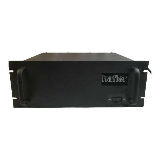
THE ha fler P505
PROFESSIONAL
POWER AMPLIFIER
INSTALLATION AND OPERATION
CAUTION:
IF THE SPEAKER FUSES BLOW,
SOME DISTORTED SOUND CAN BE
HEARD. THEREFORE IF AMPLIFIER
MALFUNCTIONS, ALWAYS CHECK
FOR BLOWN FUSES FIRST.
THE DAVID HAFLER COMPANY
5910 Crescent Boulevard, Pennsauken, New Jersey 08109
Hafler P505 Professional Power Amp
LM135
Advertisement
Table of Contents

Summary of Contents for Hafler P505
-
Page 1: Power Amplifier
Hafler P505 Professional Power Amp THE ha fler P505 PROFESSIONAL POWER AMPLIFIER INSTALLATION AND OPERATION CAUTION: IF THE SPEAKER FUSES BLOW, SOME DISTORTED SOUND CAN BE HEARD. THEREFORE IF AMPLIFIER MALFUNCTIONS, ALWAYS CHECK FOR BLOWN FUSES FIRST. LM135 THE DAVID HAFLER COMPANY... -
Page 2: Specifications
SPECIFICATIONS Power Rating: 400 watts per channel into 4 ohms at less than 0.04% THD from 20 Hz to 20 kHz with both channels driven. 255 watts per channel into 8 ohms at less than 0.025% THD from 20 Hz to 20 kHz with both channels driven. - Page 3 INTRODUCTION The P505 is a high power two channel audio power amplifier The P505 incorporates a number of protective devices. designed and constructed for professional sound applications. It Separate power supply fuses for B + and B - on each channel,...
- Page 4 #l10-32 screws and countersink heat output. Cool air is drawn in through the foam filters on the washers. It is sufficiently rigid to support the P505 safely. The panel is slightly under the 7” height to allow clearance between sides, and the warm exhaust is to the rear. Make sure this flow is not impeded, and do not allow the system to work in a closed adjacent units.
- Page 5 Monophonic Operation (Bridged Mode) at 1000 Hz, a high cable capacitance may cause oscillation in When very high power is desired, the P505 can be switched to the source equipment. Shortening the cable, or choosing a a single channel amplifier, capable of delivering more than 800 special low capacitance cable type may solve the problem.
-
Page 6: Operation
P505 can deliver more power than most speakers can excessive input signal, an extremely low load impedance, or an safely tolerate. -
Page 7: Ac Line Connections For Overseas Use
AC LINE CONNECTIONS FOR OVERSEAS USE The power transformer supplied in P505 amplifiers sold in the USA is intended for 120 volt, 60 Hz operation only. For use in other countries, a multi-voltage transformer is supplied in Export versions, available at higher cost. It has dual tapped... -
Page 8: Troubleshooting Hints
(fan. heat sources before dismantling the P505. Once the cover is sinks, circuit boards). Four screws secure it to the chassis. Be removed. do not attempt to move the amplifier by the front sure you tag every wire as you unsolder it. -
Page 9: Circuit Description
CIRCUIT DESCRIPTION Amplifier stages are fully direct coupled (DC coupling). w ith There is none of the usual volt-amp limiting in this design. Diodes D111. D12, D13 and D14 prevent the gates of the a dual differential pair for the input, and a fully complementary MOSFETs from being ov erdriven in the event of excessive MOSFET output stage. -
Page 12: Schematic Diagram
TAI I7 TS402 Thermal sensor AAI I4 RY4OI DPDT relay SZI 1 3 Fan, I20 v o l t Fan, 200-240 volt alternate AA129 S40 1 Power switch SLIII SCHEMATIC DIAGRAM P505 Power Amplifier © Copyright 1985, All rights reserved. -
Page 13: Service Policy And Limited Warranty
See “Trouble Shooting Hints”. Unsolder, do not cut, transformer leads in particular, for the transformer warranty is voided if the leads are cut too short for re-use. The Hafler Company will not be responsible for consequential damage caused by removal and/or reinstallation of the module or transformer.


Need help?
Do you have a question about the P505 and is the answer not in the manual?
Questions and answers