
Related Manuals for Delta S Series


Summary of Contents for Delta S Series
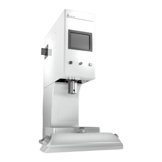
- Page 1 Delta Servo Press - S Series Installation and Maintenance Instructions www.deltaww.com...
-
Page 2: Table Of Contents
Delta Electronics Servo Press S-Series Installation and Maintenance Instructions Contents Delta Electronics Servo Press S-Series Installation and Maintenance Instructions 1. Safety Information ..............2 Safety Information Before Use ................2 Safety Information During Use ................3 Safety Information During Maintenance and Under Other Circumstances ..3 Powering System .................... -
Page 3: Safety Information
Delta Electronics Servo Press S-Series Installation and Maintenance Instructions 1. Safety Information 1.1 Safety Information Before Use Item Description Please shut down power before removing the external power lines to the unit so that the unit is in a disconnected state when the servo press will be out of service for an extended period of time. -
Page 4: Safety Information During Use
Delta Electronics Servo Press S-Series Installation and Maintenance Instructions 1.2 Safety Information During Use Item Description Please confirm there are if items interfering with punching and pressing in the surroundings of the equipment. Equipment Surroundings and Operation The emergency stop button has to be reachable by the operator and make sure that it is not covered up by surrounding items. -
Page 5: Basic Operation
Delta Electronics Servo Press S-Series Installation and Maintenance Instructions 2. Basic Operation There are the manual and external control modes for the operation. It can be switched from one mode to the other through the keyed switch. Mode Switch 2.1 Manual Operation Mode This is a two-hand press button-controlled operation model. -
Page 6: Emergency Stop Button
Delta Electronics Servo Press S-Series Installation and Maintenance Instructions 2.2 Emergency Stop Button W hen the emergency stop button is pressed, the spindle operation will stop in an instant and the buzzer will sound. In addition, a warning message appears on the human-machine interface or teaching box. -
Page 7: External Control Mode
Delta Electronics Servo Press S-Series Installation and Maintenance Instructions 2.3 External Control Mode The external control mode exercises control through communication. The following shows the I/O signal contacts. Power I/O Output (D-Sub 15Pin Female) I/O Input (D-Sub 15Pin Male) RS485 (D-Sub 9Pin) - Page 8 Delta Electronics Servo Press S-Series Installation and Maintenance Instructions Input pins Definition Definition 24V (Input) Recipe 3 Trigger Alarm Reset Safety Signal Recipe 0 Recipe 1 Recipe 2 Output pins Definition Definition 24G (Input) Ready Waiting Alarm OK/NG...
- Page 9 Delta Electronics Servo Press S-Series Installation and Maintenance Instructions RS485 pins Definition RS485 D+ RS485 D+...
-
Page 10: Comprehensive System Structure
Delta Electronics Servo Press S-Series Installation and Maintenance Instructions 3. Comprehensive System Structure 3.1 S-Series The following figure uses the AM-ESP-S010-XXXX as an example: Side view Front view Safety light curtain (This item is to be prepared or purchased optionally by the... -
Page 11: Installation Setup
Delta Electronics Servo Press S-Series Installation and Maintenance Instructions 4. Installation Setup 4.1 Method for Transporting Standard Models, and the Weight of the Whole Machine This unit comes with a hanging strap to facilitate transfer or transport of the servo press by the customer. -
Page 12: Repair
Delta Electronics Servo Press S-Series Installation and Maintenance Instructions 4.2 Repair 4.2.1 AM-ESP-S005-XXXX / AM-ESP-S010-XXXX Standard Type The fastening ports for attaching the servo press are shown in the figure below. Please use 4 general M10X1.5 hex screws (JIS strength 12.9, length 45) and apply the tightening torque of 663 kgf-cm. -
Page 13: Am-Esp-S030-Xxxx / Am-Esp-S050-Xxxx Standard Type
Delta Electronics Servo Press S-Series Installation and Maintenance Instructions 4.2.2 AM-ESP-S030-XXXX / AM-ESP-S050-XXXX Standard Type The fastening ports for attaching the servo press are shown in the figure below. Please use 4 general M20X2.5 hex screws (JIS strength 12.9, length 80) and apply the tightening torque of 5600 kgf-cm. -
Page 14: Standard Stand-Alone Model Working Platform
Delta Electronics Servo Press S-Series Installation and Maintenance Instructions 4.3 Standard Stand-alone Model Working Platform 4.3.1 AM-ESP-S005-XXXX / AM-ESP-S010-XXXX Standard Type Please produce the processing jig according to the dimensions shown in the figure. -
Page 15: Am-Esp-S030-Xxxx / Am-Esp-S050-Xxxx Standard Type
Delta Electronics Servo Press S-Series Installation and Maintenance Instructions 4.3.2 AM-ESP-S030-XXXX / AM-ESP-S050-XXXX Standard Type Please produce the processing jig according to the dimensions shown in the figure. -
Page 16: Loading And Unloading Spindle Punch
Delta Electronics Servo Press S-Series Installation and Maintenance Instructions 4.4 Loading and Unloading Spindle Punch Recommended punch jig design is provided in this section to facilitate realistic application by users. 4.4.1 AM-ESP-S005-XXXX / AM-ESP-S010-XXXX Standard Type The cross-section of the spindle is shown below. For the punch jig, please use M8 x 1.25 length 8mm set screws. -
Page 17: Am-Esp-S030-Xxxx / Am-Esp-S050-Xxxx Standard Type
Delta Electronics Servo Press S-Series Installation and Maintenance Instructions 4.4.2 AM-ESP-S030-XXXX / AM-ESP-S050-XXXX Standard Type The cross-section of the spindle is shown below. For the punch jig, please use M5 x 0.8 length 12mm hex screws. Toward the operator Toward the operator... -
Page 18: Restriction Of Jigs
Delta Electronics Servo Press S-Series Installation and Maintenance Instructions Caution: The top of the spindle punch is installed with the load cell. Do not assemble tools in a way that could result in deviations or impacts. ※The recommended jig spindle size is shown in the figure below. -
Page 19: Equipment Care And Maintenance
Delta Electronics Servo Press S-Series Installation and Maintenance Instructions 5. Equipment Care and Maintenance 5.1 Applying Oil to Equipment Please replenish the spindle lubricant. Replenish the oil through the inlet shown in the figure. Regular oil replenishment is required to prevent shortening the machine’s working life. -
Page 20: Load Cell Calibration
(after the warranty period expires). The load cell calibration tool is shown in the figure. Please follow the Operating Instructions while performing calibration and qualification or contact the Company (Delta Electronics) or contract service providers. - Page 21 5101 Davis Drive, Research Triangle Park, NC 27709, U.S.A. TEL: +7 495 644 3240 TEL: +1 - 919 - 767 - 3813 / FAX: +1 - 919 - 767 - 3969 Delta Greentech Elektronik San. Ltd. Sti. ( Turkey ) Turkey: Brazil: Delta Electronics Brazil Şerifali Mah.
Need help?
Do you have a question about the S Series and is the answer not in the manual?
Questions and answers