Sun Microsystems StorEdge 3000 Series Installation, Operation And Service Manual
Hide thumbs
Also See for StorEdge 3000 Series:
- Installation, operation and service manual (328 pages) ,
- Installation manual (96 pages) ,
- Best practices manual (86 pages)
Table of Contents
Advertisement
Quick Links
Advertisement
Chapters
Table of Contents
Troubleshooting

Related Manuals for Sun Microsystems StorEdge 3000 Series


Summary of Contents for Sun Microsystems StorEdge 3000 Series
- Page 1 Sun StorEdge 3000 Family ™ Installation, Operation, and Service Manual Sun StorEdge 3510 FC Array Sun Microsystems, Inc. www.sun.com Part No. 816-7300-15 March 2004, Revision A Submit comments about this document at: http://www.sun.com/hwdocs/feedback...
- Page 2 Copyright © 2002-2004 Dot Hill Systems Corporation, 6305 El Camino Real, Carlsbad, California 92009, USA. All rights reserved. Sun Microsystems, Inc. and Dot Hill Systems Corporation may have intellectual property rights relating to technology embodied in this product or document. In particular, and without limitation, these intellectual property rights may include one or more of the U.S. patents listed at http://www.sun.com/patents and one or more additional patents or pending patent applications in the U.S.
-
Page 3: Table Of Contents
Contents Preface xxi Product and Architecture Overview 1–1 Introduction 1–1 Field-Replaceable Units (FRUs) 1–3 1.2.1 RAID I/O Controller Modules 1–3 1.2.2 I/O Expansion Modules 1–4 1.2.3 Disk Drives 1–4 1.2.4 Battery Module 1–5 1.2.5 Power and Fan Modules 1–5 Interoperability 1–5 Fibre Channel Technology Overview 1–6 1.4.1 FC Protocols 1–6... - Page 4 1.5.3 Redundant Configuration Considerations 1–10 1.5.3.1 Host Bus Adapters 1–10 1.5.3.2 Active-to-Active Redundant Controller 1–10 1.5.3.3 Host Redundant Paths 1–10 Additional Software Tools 1–11 Site Planning 2–1 Customer Obligations 2–2 Safety Precautions 2–2 Environmental Requirements 2–3 2.3.1 Electromagnetic Compatibility (EMC) 2–3 Electrical and Power Specifications 2–4 Physical Specifications 2–5 Layout Map 2–5...
- Page 5 Connecting Your Fibre Channel Array 4–1 Converting Your Front Bezel Locks So the Keys Cannot Be Removed 4–2 Fibre Channel Array Connections 4–5 Connecting the Chassis to an AC Power Outlet 4–6 Connecting the Chassis to DC Power Outlets 4–7 Powering Up and Checking LEDs 4–9 Reviewing and Changing SFP Ports (Optional) 4–10 4.6.1...
- Page 6 5.3.1 Out-of-Band Connection 5–6 Configuration Overview 5–7 5.4.1 Point-to-Point Configuration Guidelines 5–9 5.4.2 A SAN Point-to-Point Configuration Example 5–11 5.4.3 A DAS Loop Configuration Example 5–15 5.4.4 Larger Configurations 5–18 Initial Configuration Steps 5–18 5.5.1 Viewing the Initial Firmware Windows 5–19 5.5.2 Checking Available Physical Drives 5–20 5.5.3...
- Page 7 5.6.5 Creating Device Files for the Solaris Operating Environment 5–58 5.6.6 Saving Configuration (NVRAM) to a Disk 5–59 Using Software to Monitor and Manage the Sun StorEdge 3510 FC Array 5–60 5.7.1 Other Supported Software 5–60 5.7.2 Enabling VERITAS DMP 5–61 5.7.3 The VERITAS Volume Manager ASL 5–61 Checking LEDs 6–1...
- Page 8 7.4.7 Identifying Fans 7–21 7.4.8 Viewing Event Logs on the Screen 7–22 Restoring Your Configuration (NVRAM) From a File 7–24 Upgrading Firmware 7–26 7.6.1 Patch Downloads 7–27 7.6.2 Controller Firmware Upgrade Features 7–27 7.6.3 Installing Firmware Upgrades 7–28 7.6.4 Installing Controller Firmware Upgrades From the Firmware Application 7–29 Replacing the Front Bezel and Ear Caps 7–30 7.7.1...
- Page 9 8.9.1 Power Supply and Fan Module 8–16 8.9.2 Drive LEDs 8–19 8.9.3 Front Panel LEDs 8–21 8.9.4 I/O Controller Module 8–25 8.10 Using the Reset Button 8–27 8.11 Silencing Audible Alarms 8–27 A. Sun StorEdge 3510 FC Array Specifications A–1 Physical Specifications A–2 Sun StorEdge 3510 FC Array Highlights A–3 A.2.1...
- Page 10 Connecting Sun StorEdge 3510 FC JBOD Arrays B–9 B.7.1 Single-Port Connections to Sun StorEdge 3510 FC JBOD Arrays B–9 B.7.2 Dual-Port Connections to Sun StorEdge 3510 FC JBOD Arrays B–10 B.7.3 Changing Your SFP Configuration on JBOD Arrays B–12 B.7.4 Connecting the Sun StorEdge 3510 FC JBOD Array to a Host Computer B–13 Enabling Sun StorEdge 3510 FC JBOD Array Support B–13...
- Page 11 D. Record of Settings D–1 View and Edit Logical Drives D–2 D.1.1 Logical Drive Information D–2 D.1.2 Logical Drive Partition Information D–3 View and Edit Host LUNs D–4 D.2.1 LUN Mappings D–4 View and Edit SCSI Drives D–5 View and Edit SCSI Channels D–6 View and Edit Peripheral Devices D–7 D.5.1 View System Information D–7...
- Page 12 H. Configuring a Linux Server H–1 Setting Up the Serial Port Connection H–1 Accessing the Firmware Application From a Linux Server H–3 Checking the Adapter BIOS H–4 Multiple LUN Linux Configuration H–5 Making an ext3 File System for Linux H–6 Creating a File System H–7 Creating a Mount Point and Mounting the File System Manually H–7 Mounting the File System Automatically H–8...
- Page 13 Definitions of Common Terms J–6 Creating a Physical Volume J–7 Creating a Volume Group J–7 Creating a Logical Volume J–9 Creating an HP-UX File System J–10 J.10 Mounting the File System Manually J–10 J.11 Mounting the File System Automatically J–10 J.12 Determining the World Wide Name for HP-UX Hosts J–11 K.
- Page 14 Sun StorEdge 3000 Family Installation, Operation, and Service Manual • March 2004...
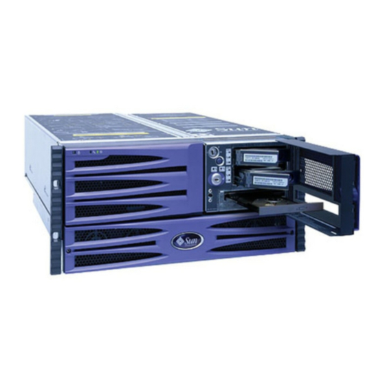
- Page 15 Figures Sun StorEdge 3510 FC Array Front View 1–1 FIGURE 1-1 Front Bezel and Front Bezel Locks of an Array 4–2 FIGURE 4-1 Sequence of Steps to Change Front Bezel Locks So Keys Cannot Be Removed 4–3 FIGURE 4-2 Hardware Connections on the Back of a Dual-Controller FC Array 4–5 FIGURE 4-3 Installed Cord Lock 4–7 FIGURE 4-4...
- Page 16 Partitions in Logical Configurations 5–42 FIGURE 5-5 Mapping Partitions to Host ID/LUNs 5–47 FIGURE 5-6 Example of LUN Filtering 5–52 FIGURE 5-7 Front Panel LEDs 6–2 FIGURE 6-1 Chassis Ear LEDs and Reset Button on Front Panel 6–2 FIGURE 6-2 I/O Controller Module and Battery Module LEDs 6–5 FIGURE 6-3 I/O Expansion Module for an Expansion Unit 6–6...
- Page 17 Chassis Ear LEDs and Reset Button on Front Panel B–18 FIGURE B-6 I/O Module for a Sun StorEdge 3510 FC JBOD Array B–20 FIGURE B-7 AC Power Supply and Fan Module B–21 FIGURE B-8 DC Power Supply and Fan Module B–21 FIGURE B-9 JBOD or Expansion Unit Flowchart 1 of 2 B–25 FIGURE B-10...
- Page 18 xviii Sun StorEdge 3000 Family Installation, Operation, and Service Manual • March 2004...
- Page 19 Tables Sun StorEdge 3510 FC Array Configuration Options 1–2 TABLE 1-1 Environmental Specifications 2–3 TABLE 2-1 Power Specifications 2–4 TABLE 2-2 Physical Specifications 2–5 TABLE 2-3 Preinstallation Worksheet 2–8 TABLE 2-4 Host and Fabric Switch Connectivity Summarized 2–9 TABLE 2-5 List of Available FRUs 3–4 TABLE 3-1 DC Cable Wiring for Cable 35-00000148 4–8...
- Page 20 Cylinder and Head Mapping for the Solaris Operating Environment 5–39 TABLE 5-9 Configuration for 1024 LUNs 5–48 TABLE 5-10 Front Panel LED Status When Array Is First Powered On 6–1 TABLE 6-1 Front Panel LEDs 6–3 TABLE 6-2 I/O Controller Module and Battery Module LEDs 6–6 TABLE 6-3 Power Supply LEDs 6–8 TABLE 6-4...
-
Page 21: Preface
3510 FC Array. This guide is written for experienced system administrators who are familiar with Sun Microsystems hardware and software products. Caution – Read the Sun StorEdge 3000 Family Safety, Regulatory, and Compliance Manual before beginning any procedure in this manual. - Page 22 Appendix B provides information about standalone JBOD arrays. Appendix C provides information about failed component alarm codes. Appendix D provides tables for recording configuration data. Appendix E provides pinout identification for each connector. Appendix F provides instructions on configuring a Solaris™ server. Appendix G provides instructions on configuring a Windows 2000 or Windows 2000 Advanced server.
- Page 23 Shell Prompts Shell Prompt C shell machine-name% C shell superuser machine-name# Bourne shell and Korn shell Bourne shell and Korn shell superuser Typographic Conventions Typeface Meaning Examples The names of commands, files, Edit your.login file. AaBbCc123 and directories; on-screen Use ls -a to list all files. computer output % You have mail.
- Page 24 Related Documentation Title Part Number Sun StorEdge 3510 FC Array Release Notes 816-7301 Sun StorEdge 3000 Family Best Practices Manual 816-7325 Sun StorEdge 3000 Family RAID Firmware 3.25 and 3.27 User’s Guide 817-3711 Sun StorEdge 3000 Family Configuration Service 1.5 User’s Guide 817-3337 Sun StorEdge 3000 Family Diagnostic Reporter 1.5 User’s Guide 817-3338...
- Page 25 Contacting Sun Technical Support For late-breaking news and troubleshooting tips, review the Sun StorEdge 3510 FC Array Release Notes located at: http://www.sun.com/products-n-solutions/hardware/docs/ Network_Storage_Solutions/Workgroup/3510 If you have technical questions about this product that are not answered in the documentation, go to: http://www.sun.com/service/contacting To initiate or check on a USA-only service request, contact Sun support at: 800-USA-4SUN...
- Page 26 Sun Welcomes Your Comments Sun is interested in improving its documentation and welcomes your comments and suggestions. You can submit your comments by going to: http://www.sun.com/hwdocs/feedback Please include the title and part number of your document with your feedback: Sun StorEdge 3000 Family Installation, Operation, and Service Manual, part number 816- 7300-15.
-
Page 27: Figure 1-1 Sun Storedge 3510 Fc Array Front View
C H A P T E R Product and Architecture Overview This chapter provides a brief overview of your Sun StorEdge 3510 FC (Fibre Channel) Array. Topics covered in this chapter are: “Introduction” on page 1-1 “Field-Replaceable Units (FRUs)” on page 1-3 “Interoperability”... -
Page 28: Table 1-1 Sun Storedge 3510 Fc Array Configuration Options
A redundant array of independent disks (RAID) with a single controller A RAID array with two controllers An expansion unit that connects to and is managed by a RAID array A Just a Bunch of Disks (JBOD) array that has no RAID controller and connects to, and is managed by, a host server “Using Standalone JBOD Arrays”... -
Page 29: Product And Architecture Overview
* A disk array with no controller. Each expansion unit has two Fibre Channel loops that can provide redundant data paths back to the RAID array. † A disk array with no controller that is connected directly to a host computer, with no RAID array in the loop. ‡... -
Page 30: I/O Expansion Modules
Each RAID controller module can support up to 1 gigabyte of Sychronous Dynamic Random Access Memory (SDRAM) with Error Control Check (ECC) memory. In addition, each controller supports 64 megabytes (Mbyte) of on-board memory. Two Application Specific Integrated Circuit (ASIC) controller chips handle the interconnection between the controller bus, DRAM memory, and Peripheral Component Interconnect (PCI) internal buses. -
Page 31: Battery Module
In the event of a single disk drive failure, with the exception of RAID 0, the system continues to service all I/O requests. Either the mirrored data or parity data is utilized in the rebuilding of the failed drives data to a spare disk drive, assuming one is assigned. -
Page 32: Fibre Channel Technology Overview
Note – For information about supported versions of these operating environments, refer to the release notes for your array. The array does not require any host-based software for configuration, management, and monitoring, which are handled through the built-in firmware application. The console window can be accessed via the DB-9 communications (COM) port using the command, or via the Ethernet port using the telnet command. -
Page 33: Fc Topologies
1.4.2 FC Topologies The presence or lack of switches establishes the topology of an FC environment. In a direct attached storage (DAS) topology, servers connect straight to arrays without switches. In a storage area network (SAN) topology, servers and arrays connect to an FC network created and managed by switches. -
Page 34: Scalability
Controller communications over Fibre Channel. Selectable either through dedicated loops or all drive loops. This allows a more flexible configuration of redundant controllers. 1.4.5 Scalability The Fibre Channel architecture brings scalability and easier upgrades to storage. Storage expansion can be as easy as cascading another expansion unit to a configured RAID array without powering down the running system. -
Page 35: Disk Drive Fc Architecture
In a dual RAID controller configuration, both RAID controllers have the same channel designators, due to the architecture of the loops within the chassis. Each host and drive channel of the top RAID controller shares a loop with the matching channel on the bottom RAID controller. -
Page 36: Redundant Configuration Considerations
1.5.3 Redundant Configuration Considerations This section provides information about setting up redundant configurations for increased reliability. 1.5.3.1 Host Bus Adapters Fibre Channel is widely applied to storage configurations with topologies that aim to avoid loss of data by component failure. As a rule, the connections between source and target should be configured in redundant pairs. -
Page 37: Additional Software Tools
Additional Software Tools The following additional software tools are available on the Sun StorEdge 3000 Family Professional Storage Manager CD, provided with your array: Sun StorEdge Configuration Service, a management and monitoring program Sun StorEdge Diagnostic Reporter software, a monitoring utility Sun StorEdge CLI, a command-line utility to monitor and manage the array. - Page 38 1-12 Sun StorEdge 3000 Family Installation, Operation, and Service Manual • March 2004...
-
Page 39: Site Planning
C H A P T E R Site Planning This chapter outlines the site-planning requirements and basic safety requirements for the installation and use of the Sun StorEdge 3510 FC Array. Complete a preinstallation worksheet and prepare the site for installation according to the worksheet details and the specified site-planning requirements. -
Page 40: Customer Obligations
Customer Obligations The customer is obliged to inform Sun Microsystems, Inc. of any and all ordinances and regulations that would affect installation. Caution – When selecting an installation site for the Sun StorEdge 3510 FC Array, choose a location that avoids excessive heat, direct sunlight, dust, or chemical exposure. -
Page 41: Environmental Requirements
To reduce the risk of electric shock, do not plug Sun products into any other type of power system. Sun products are designed to work with single-phase power systems having a grounded neutral conductor. Contact your facilities manager or a qualified electrician if you are not sure what type of power is supplied to your building. -
Page 42: Electrical And Power Specifications
The supplied arrays require voltages within minimum fluctuation. The facilities voltage supplied by the customer must maintain a voltage with not more than (+/–) 5 percent fluctuation. The customer facilities must provide suitable surge protection. Electrical and Power Specifications The Sun StorEdge 3510 FC Array requires two independent power sources. Each array has two power supply and fan modules for redundancy. -
Page 43: Physical Specifications
Physical Specifications Use the physical specifications in to plan the location of your array. TABLE 2-3 Physical Specifications TABLE 2-3 Category Description Dimensions 2U (3.45 inches / 8.76 cm) height 20 inches / 50.8 cm chassis depth 17.5 inches / 44.6 cm width (19 inches / 48.26 cm with ears) Installation clearances For FRU component removal and replacement, 15-inches (37 cm) is required front and back. -
Page 44: Tabletop Placement
Provide two separate power sources for the array. These power sources must be independent of each other, and each must be controlled by a separate circuit breaker at the power distribution point. 2.6.2 Tabletop Placement The Sun StorEdge 3510 FC Array can be positioned on a desk or a table. Follow these guidelines when preparing a tabletop placement for your system: Choose a desk or a table that can support 50 pounds for each fully configured array you plan to place on it. -
Page 45: Console And Other Requirements
Console and Other Requirements A console with at least one serial port or Ethernet connection is necessary for installation and configuration of your Sun StorEdge 3510 FC Array. Once you have configured your array with an IP address, the Ethernet port can also be useful for configuring the array. -
Page 46: Table 2-4 Preinstallation Worksheet
What cable lengths are required? _________________ Are there any power strips or power sequencers in the rack? Yes / No Are they supplied by Sun Microsystems, Inc.? Yes / No If yes, part number: ___________ If not, quantity of plugs/outlets required: __________ / __________ IP address Array IP address: ______.______.______.______... -
Page 47: Table 2-5 Host And Fabric Switch Connectivity Summarized
Host and Fabric Switch Connectivity Summarized TABLE 2-5 Host or Fabric Switch Connectivity - Host or Fabric Switch #1 Host or Fabric switch name: _____________________________________ Host or Fabric switch make/model: ________________________________ HBA connector types: _____________________________ Cable distance from the array to the host(s): ___________ Operating environment: ________________________________ Patches installed: ________________________________ IP addresses:... - Page 48 2-10 Sun StorEdge 3000 Family Installation, Operation, and Service Manual • March 2004...
-
Page 49: Unpacking Your Fc Array
C H A P T E R Unpacking Your FC Array This chapter describes the procedure for unpacking your Sun StorEdge 3510 FC Array package. The following topics are covered in this chapter: “Opening Your Package” on page 3-2 “Checking the Package Contents” on page 3-3 “Customer-Provided Cables”... -
Page 50: Opening Your Package
Opening Your Package Follow these guidelines for unpacking the equipment. Caution – To avoid personal injury or damage to the equipment during installation, always use two people to remove the unit from its container. This unit weighs approximately 50 pounds. 1. -
Page 51: Checking The Package Contents
Checking the Package Contents Inspect your Sun StorEdge 3510 FC Array packages for standard items as well as purchased options before you begin installation. If any parts are missing or damaged, contact your sales representative immediately. 3.2.1 Standard Sun StorEdge 3510 FC Array Package Quantity Item One or more of the following arrays:... -
Page 52: Field-Replaceable Units
3.2.2 Field-Replaceable Units Check that you received all field-replaceable units (FRUs) ordered with your Sun StorEdge 3510 FC Array. For additional FRUs, consult your sales representative. For instructions on how to install or replace FRUS, review the following manuals located on the product web site: Sun StorEdge 3000 Family Rack Installation Guide for 2U Arrays Sun StorEdge 3000 Family FRU Installation Guide... -
Page 53: Customer-Provided Cables
Customer-Provided Cables Customers must provide a minimum of one Fibre Channel cable per host to connect a host to a RAID array. Two Fibre Channel cables are required for a redundant path configuration. To obtain qualified cables, consult your Sun sales representative. Mounting Your Array in a Rack or Cabinet Refer to Sun StorEdge 3000 Family Rack Installation Guide for instructions on how to... - Page 54 Sun StorEdge 3000 Family Installation, Operation, and Service Manual • March 2004...
-
Page 55: Connecting Your Fibre Channel Array
C H A P T E R Connecting Your Fibre Channel Array This chapter describes procedures for cabling the Sun StorEdge 3510 FC Array and for connecting the array to power and to network devices. The following topics are covered in this chapter: “Converting Your Front Bezel Locks So the Keys Cannot Be Removed”... -
Page 56: Converting Your Front Bezel Locks So The Keys Cannot Be Removed
Caution – When positioning the array, do not block the air vents at the front or back of the unit. Follow all safety precautions specified in the Sun StorEdge 3000 Family Safety, Regulatory, and Compliance Manual. Caution – When you power off an array, wait five seconds before you power it back on. -
Page 57: Figure 4-2 Sequence Of Steps To Change Front Bezel Locks So Keys Cannot Be Removed
Sequence of Steps to Change Front Bezel Locks So Keys Cannot Be Removed FIGURE 4-2 3. Hold the key in place and use a 12 mm or 3/8-inch nut driver to remove the locking nut that holds the pawl in place, as shown in the first panel of FIGURE 4-2 Caution –... - Page 58 6. Use the key to turn the lock 180 degrees, as shown in the third panel of FIGURE 4-2 7. Replace the pawl in the same orientation as before, as shown in the fourth panel FIGURE 4-2 8. Hold the key in place and use the nut driver to refasten the locking nut that holds the pawl in place, as shown in the fifth panel of .
-
Page 59: Fibre Channel Array Connections
Fibre Channel Array Connections identifies the hardware connections on the back of a dual-controller FC FIGURE 4-3 array. Servers and consoles FC devices Management console FC expansion units/FC arrays FC device connections application/data servers and consoles Hardware Connections on the Back of a Dual-Controller FC Array FIGURE 4-3 Chapter 4 Connecting Your Fibre Channel Array... -
Page 60: Connecting The Chassis To An Ac Power Outlet
Management is in-band through fibre host connections and out-of-band through the serial port and Ethernet port on the back of each controller. Connecting the Chassis to an AC Power Outlet When you connect the AC power cords, you should install the provided two cord locks at the same time. -
Page 61: Connecting The Chassis To Dc Power Outlets
Installed Cord Lock FIGURE 4-4 10. Repeat this procedure for the second cord lock and second power cable. Connecting the Chassis to DC Power Outlets Two DC power cords are packaged with each DC array. To connect the DC power cords, perform the following procedure: 1. -
Page 62: Table 4-1 Dc Cable Wiring For Cable 35-00000148
2. Check the DC cable part number and wire labels carefully before connecting the cable to the source. DC Cable Wiring for Cable 35-00000148 TABLE 4-1 Pin Number Voltage Color Return GND (Chassis Ground) Green/Yellow -48vdc Black DC Cable Wiring for Cable 35-00000156 TABLE 4-2 Pin Number Voltage... -
Page 63: Powering Up And Checking Leds
Powering Up and Checking LEDs Perform the initial check of the array according to the following procedure: 1. Connect two AC (or DC) power cables to the power and fan modules on the back of the array. 2. Power on the array by turning on each power switch. “Power-On Sequence”... -
Page 64: Reviewing And Changing Sfp Ports (Optional)
See the chapter “Checking LEDs” on page 6-1 for more information about your array’s LEDs. Reviewing and Changing SFP Ports (Optional) Each I/O controller module has six ports that accept SFP transceivers. These ports are labeled FC0 through FC5. The default configurations do not include an SFP connector on every SFP port. -
Page 65: Default Sfp Placement
Two drive ports on channel 3 Two drive ports on channel 2 Dedicated Drive Channels 2 (on the Upper Controller) and 3 (on the Lower Controller) in a FIGURE 4-6 Dual-Controller Array The controller module in slot A (the upper slot) houses drive channel 2, which connects to the 12 internal disk drives through their A ports. -
Page 66: Figure 4-8 Default Dual-Controller Sfp Placement
The lower I/O controller module has SFPs in the FC1, FC3, and FC5 ports. This configuration provides connections to all four host channels as well as to both drive channels. Host port FC0 Drive port FC2 Host port FC4 Host port FC1 Drive port FC3 Host port FC5 Default Dual-Controller SFP Placement FIGURE 4-8... -
Page 67: Changing Your Sfp Configuration
Default SFP Placement Default JBOD Expansion Unit SFP Placement FIGURE 4-10 4.6.3 Changing Your SFP Configuration Fibre Channel arrays use SFP connectors to attach to hosts and expansion units. These SFP connectors resemble the one shown in , with a single connector FIGURE 4-11 at the end that plugs into an SFP port on the array or expansion unit chassis, and a duplex jack into which you insert a cable to make the connection. -
Page 68: Configuring A Com Port To Connect To A Raid Array
Configuring a COM Port to Connect to a RAID Array The RS-232 COM port on either controller module is used to configure and monitor the RAID array. It can be connected to a VT100 terminal or terminal emulation program, to a terminal server, or to the serial port of a server. 1. - Page 69 Caution – If you assign an IP address to an array to manage it out-of-band, for security reasons make sure that the IP address is on a private network rather than a publicly routable network. There are two main reasons for placing your arrays on a private subnet: When your array is on a public network, it is susceptible to viruses, worms, and other malware attacks.
-
Page 70: Setting Up Out-Of-Band Management Over Ethernet
Note – You must reset the controller for the configuration to take effect. You are prompted to reset the controller. 10. Select Yes to reset the controller. The controller takes a few minutes to format a small storage sector on each physical drive before logical drives can be successfully initialized. -
Page 71: Cabling To Expansion Units
5. Press Ctrl-L to refresh the screen and view the Main Menu. Note – If you reset the controller during a telnet session, you are disconnected from the RAID array. Use the telnet command to log back in to the array. 6. -
Page 72: Figure 4-12 Raid Array Attached To Two Hosts And Two Expansion Units
RAID array Expansion unit 1 Expansion unit 2 Loop A (left-side drive ports) Loop B (right-side drive ports) Cable to drive Cable to host RAID Array Attached to Two Hosts and Two Expansion Units FIGURE 4-12 In the RAID array, two of the unused SFP host ports could be used to provide redundant pathing to the two servers, and the other four unused SFP host ports could be connected to two more servers in a redundant configuration. -
Page 73: Scaling Beyond 36 Disks
Similarly, you can connect expansion units to other channels (which are separate from channels 2 and 3) if you configure channels 0, 1, 4, or 5 as drive channels. For details, refer to “Configuring FC Channels as Host or Drive (Optional)” on page 5-22. -
Page 74: Setting Loop Ids On Expansion Units
Refer to the Sun StorEdge 3000 Family Best Practices Manual for the Sun StorEdge 3510 FC array for cabling diagrams for configurations ranging from three to eight expansion units. Note – Large configurations may require the use of one or more optional extended- length cables, part number X9732A. -
Page 75: Figure 4-14 Id Switch Located On The Left Front Side Of The Array Or Expansion Unit
Caution – To avoid damage to the cap, do not pull the cap forward directly or pull from only its top or bottom. Press to change the ID number ID Switch Located on the Left Front Side of the Array or Expansion Unit FIGURE 4-14 4. -
Page 76: Table 4-3 Id Switch Settings For Expansion Units
The ID switch offers eight ID ranges. Each set contains 16 IDs (the last four IDs in each range are ignored). These ranges are shown in TABLE 4-3 ID Switch Settings for Expansion Units TABLE 4-3 ID Switch Setting Range of IDs 0–15 16–31 32–47... -
Page 77: Connecting Ports To Hosts
9. Use the key to lock both bezel locks. 4.12 Connecting Ports to Hosts In a default array configuration, channels 0, 1, 4, and 5 are host channels, so you can directly connect an FC array to four host computers. SFP connectors are plugged into channels 0 and 4 on the upper controller and channels 1 and 5 on the lower controller for this purpose. - Page 78 c. Host computers When you power on a controller, the Tip connection window displays a series of messages such as the following: 3510 Disk Array is installed with 1024MBytes SDRAM Total SCSI channels: 6 SCSI channel: 0 is a host channel, id: 40 SCSI channel: 1 is a host channel, id: 41 SCSI channel: 2 is a drive channel, id: 14, 15 SCSI channel: 3 is a drive channel, id: 14, 15...
-
Page 79: First-Time Configuration
C H A P T E R First-Time Configuration This chapter summarizes the most common procedures used for first-time configuration. This chapter covers the following topics: “Controller Defaults and Limitations” on page 5-2 “Planning for Reliability, Availability, and Serviceability” on page 5-2 “Dual-Controller Considerations”... -
Page 80: Controller Defaults And Limitations
Subsequent chapters in this manual describe further procedures used to complete the installation and configuration of FC arrays. The flexible architecture of the Sun StorEdge 3510 FC Array makes many configurations possible. Controller Defaults and Limitations This section describes default configurations and certain controller limitations. 5.1.1 Planning for Reliability, Availability, and Serviceability... -
Page 81: Dual-Controller Considerations
5.1.2 Dual-Controller Considerations The following controller functions describe the redundant controller operation. Both controllers must be exactly the same. They must operate with the same firmware version, the same size of memory, and the same number of host and drive channels. If one controller in a dual-controller configuration is replaced with a field-replaceable unit (FRU) controller, the array automatically compares the firmware versions of the two controllers. -
Page 82: Single-Controller Considerations
5.1.3 Single-Controller Considerations In a single-controller configuration, keep the controller as the primary controller at all times and assign all logical drives to the primary controller. The primary controller controls all logical drive and firmware operations. In a single-controller configuration, the controller must be the primary controller or the controller cannot operate. -
Page 83: Table 5-1 Battery Status Indicators
A battery module whose status shows one or more + signs can support cache memory for 72 hours. As long as one or more + signs are displayed, your battery is performing correctly. Battery Status Indicators TABLE 5-1 Battery Display Description ----- Discharged;... -
Page 84: Write-Back And Write-Through Cache Options
5.2.2 Write-Back and Write-Through Cache Options Unfinished writes are cached in memory in write-back mode. If power to the array is discontinued, data stored in the cache memory is not lost. Battery modules can support cache memory for 72 hours. Write cache is not automatically disabled when the battery is offline due to battery failure or a disconnected battery. -
Page 85: Configuration Overview
Configuration Overview The Sun StorEdge 3510 FC Array is preconfigured and requires minimal configuration. All procedures can be performed by using the COM port. You can perform all procedures except the assignment of an IP address through an Ethernet port connection to a management console. The typical sequence of steps for completing a first-time configuration of the array is 1. - Page 86 of the single controller. If you disable the Redundant Controller Function and reconfigure the controller with the Autoconfigure option or as a secondary controller, the controller module becomes inoperable and will need to be replaced. Note – While the ability to create and manage logical volumes remains a feature of Sun StorEdge 3000 family FC and SCSI RAID arrays for legacy reasons, the size and performance of physical and logical drives have made the use of logical volumes obsolete.
-
Page 87: Point-To-Point Configuration Guidelines
Note – Resetting the controller can result in occasional host-side error messages such as parity error and synchronous error messages. No action is required and the condition corrects itself as soon as reinitialization of the controller is complete. 14. Save the configuration to a disk. See “Saving Configuration (NVRAM) to a Disk”... - Page 88 The controller displays a warning if the user is in point-to-point mode and tries to add an ID to the same channel but on the other controller. The warning is displayed because you have the ability to disable the internal connection between the channels on the primary and secondary controller using the set inter- controller link CLI command and, by doing this, you can have one ID on the primary and another ID on the secondary as a legal operation.
-
Page 89: A San Point-To-Point Configuration Example
Note – When in loop mode and connected to a Fabric switch, each host ID is displayed as a loop device on the switch so that, if all 16 IDs are active on a given channel, the array looks like a loop with 16 nodes attached to a single switch FL port. - Page 90 Important rules to remember are: A single logical drive can be mapped to only one controller, either the primary controller or the secondary controller. In a point-to-point configuration, only one host ID per channel is allowed. The host ID can be assigned to the primary controller and be a PID, or it can be assigned to the secondary controller and be a SID.
- Page 91 Server 0 Server 1 Switch 0 Switch 1 PID 40 PID 41 SID 50 SID 51 Map LG0 to PIDs 40 and 41 Map LG1 to SIDs 50 and 51 : Host port on channel number N PID 40 / PID41 : Host IDs on primary controller SID 50 / SID51 : Host IDs on secondary controller N/A : Not applicable (no ID on that controller) : Port bypass circuit...
-
Page 92: Table 5-2 Example Point-To-Point Configuration With Two Logical Drives In A Dual-Controller Array
Example Point-to-Point Configuration With Two Logical Drives in a Dual- TABLE 5-2 Controller Array Logical Channel Primary ID Secondary ID Task Drive Number Number Number Map 32 partitions of LG0 to CH0 LG 0 0-31 Duplicate-map 32 partitions of LG 0 0-31 LG0 to CH1 Map 32 partitions of LG1 to CH4... -
Page 93: A Das Loop Configuration Example
8. Map logical drive 1 to channels 4 and 5 of the secondary controller. Map LUN numbers 0 through 31 to the single ID on each host channel. Since each set of LUNs is assigned to two channels for redundancy, the total working maximum number of LUNs is 64 LUNs. -
Page 94: Figure 5-2 A Das Configuration With Four Servers, A Dual-Controller Array, And Two Expansion Units
Server 1 Server 2 Server 3 Server 4 A DAS Configuration With Four Servers, a Dual-Controller Array, and Two FIGURE 5-2 Expansion Units Establishing complete redundancy and maintaining high availability requires the use of multipathing software such as Sun StorEdge Traffic Manager software. To configure for multipathing: 1. -
Page 95: Table 5-3 Example Primary And Secondary Id Numbers In A Loop Configuration With Two Ids Per Channel
Perform the following steps, which are described in more detail later in this manual, to set up a DAS loop configuration based on FIGURE 5-2 1. Check the position of installed SFPs. Move them as necessary to support the connections needed. You need to add SFP connectors to support more than four connections between servers and a Sun StorEdge 3510 FC Array. -
Page 96: Larger Configurations
12. Connect the second server to port 1 of the lower controller and port 4 of the upper controller. 13. Connect the third server to port 0 of the lower controller and port 5 of the upper controller. 14. Connect the fourth server to port 1 of the upper controller and port 4 of the lower controller. -
Page 97: Viewing The Initial Firmware Windows 5-19
5.5.1 Viewing the Initial Firmware Windows You see the initial controller screen when you first access the RAID controller firmware. The initial screen is displayed when the RAID controller is powered on. Note – Since Fibre Channel and SCSI arrays share the same controller firmware, most menu options are the same. -
Page 98: Checking Available Physical Drives
3. Proceed to configure the array using options from the Main Menu as described in the rest of this chapter. Firmware Main Menu FIGURE 5-3 5.5.2 Checking Available Physical Drives Before configuring disk drives into a logical drive, you must know the status of physical drives in your enclosure. - Page 99 Note – If a drive is installed but is not listed, it might be defective or installed incorrectly. When the power is on, the controller scans all hard drives that are connected through the drive channels. If a hard drive was connected after the controller completed initialization, use the “Scan scsi drive”...
-
Page 100: Configuring Fc Channels As Host Or Drive (Optional)
5.5.3 Configuring FC Channels as Host or Drive (Optional) Sun StorEdge 3510 FC RAID arrays are preconfigured when they arrive from the factory. Default channel settings and rules are specified as follows: Default channel settings are: CH 0, CH 1, CH 4, and CH 5 = Host channels CH 2 and CH 3 = Drive channels Channels 2 and 3 (CH 2 and 3) must be drive channels. - Page 101 3. Choose “channel Mode.” A menu of channel mode options is displayed. 4. Modify the channel to suit your requirements. Refer to the Sun StorEdge 3000 Family RAID Firmware User’s Guide for more information about modifying channels. 5. Choose Yes to confirm that you want to change the host or drive assignment. A confirmation message is displayed: NOTICE: Change made to this setting will NOT take effect until the controller is RESET.
-
Page 102: Choosing Loop Or Point-To-Point Fibre Connection
5.5.4 Choosing Loop or Point-to-Point Fibre Connection To confirm or change the fibre connection for the array, perform the following steps: 1. Choose “view and edit Configuration parameters → Host-side SCSI Parameters → Fibre Connection Option.” 2. If you want to view or change the Fibre Connection Option, choose either “Loop only”... -
Page 103: Editing And Creating Additional Host Ids (Optional)
NOTICE: Change made to this setting will NOT take effect until the controller is RESET. Prior to resetting the controller, operation may not proceed normally. Do you want to reset the controller now? 4. Choose Yes to reset the controller. 5.5.5 Editing and Creating Additional Host IDs (Optional) - Page 104 Note – To map 1024 partitions in loop mode, you must add additional host IDs so that 32 IDs are mapped to the array’s channels. Several configurations are possible, such as eight IDs mapped to each of the four host channels or sixteen IDs mapped to two channels and none to the other two.
-
Page 105: Selecting Sequential Or Random Optimization
7. Confirm your selection by choosing Yes and pressing Return. A confirmation message is displayed: NOTICE: Change made to this setting will NOT take effect until the controller is RESET. Prior to resetting the controller, operation may not proceed normally. Do you want to reset the controller now? 8. -
Page 106: Maximum Number Of Disks And Maximum Usable Capacity For Random And Sequential Optimization
from the drive as large-block, sequential files. Database and transaction-processing applications read and write data from the drive as small-block, randomly accessed files. There are two limitations that apply to the optimization modes: One optimization mode must be applied to all logical drives in an array. Once the optimization mode is selected and data written to logical drives, the only way to change the optimization mode is to back up all data to another location, delete all logical configurations of drives, reconfigure the logical drive... -
Page 107: Table 5-6 Maximum Usable Capacity (Gbyte) Per Logical Drive For A 2U Array
Maximum Usable Capacity (Gbyte) per Logical Drive for a 2U Array TABLE 5-6 Disk Capacity RAID 5 RAID 5 RAID 3 RAID 3 RAID 1 RAID 1 RAID 0 RAID 0 Random Sequential Random Sequential Random Sequential Random Sequential 36.2 1086 1086 1122... -
Page 108: Table 5-7 Raid Level Definitions
For a 5-drive array, the RAID array is preconfigured as follows: One RAID 5 logical drive, consisting of four physical drives One global spare The following table highlights the RAID levels available. RAID Level Definitions TABLE 5-7 RAID Level Description RAID 0 Striping without data redundancy;... -
Page 109: Completing Basic Configuration
5.5.8 Completing Basic Configuration In a point-to-point configuration, the last required step is mapping the logical drives to host LUNs. In loop mode, you have additional options to pursue, if needed, in addition to the mapping requirement: Optionally, define any additional partitions for each logical drive. See “Partitioning a Logical Drive (Optional)”... -
Page 110: Figure 5-4 Example Of An Allocation Of Local And Spare Drives In Logical Configurations
For redundancy across separate channels, you can also create a logical drive containing drives distributed over separate channels. You can then partition the logical unit into one or several partitions..to other drives on loop Drive channel 0 ...to other drives on loop Drive channel 1 ID14 Global spare... - Page 111 2. Select the first available unassigned logical drive (LG) and press Return to proceed. You can create as many as eight logical drives from drives on any loop. 3. When prompted to “Create Logical Drive?” choose Yes. A pull-down list of supported RAID levels is displayed. 4.
- Page 112 5. Select your member drives from the list of available physical drives and press Return. The drives can be tagged for inclusion by highlighting the drive and then pressing Return. An asterisk mark (*) is displayed on the selected physical drives. To deselect a drive, press Return again on the selected drive.
- Page 113 b. After all physical drives have been selected for the logical drive, press the Esc key to continue to the next series of options. A list of selections is displayed. 6. (Optional) Set the maximum physical drive capacity and assign spares. a.
- Page 114 Note – A global spare cannot be created while creating a logical drive. The spare chosen here is a local spare and automatically replaces any failed disk drive in this logical drive. The local spare is not available for any other logical drive.
- Page 115 a. Press the Esc key or choose No and press Return to exit from this window without changing the controller assignment. b. Choose Yes, press Return to confirm, and then press the Esc key to continue when all the preferences have been set. A confirmation window is displayed on the screen.
-
Page 116: Table 5-8 Cylinder And Head Mapping For The Solaris Operating Environment
8. Choose “view and edit Logical drives” to view the first created logical drive (P0) on the first line of the status window. 5.5.10 Preparing for Logical Drives Larger Than 253 Gbyte The Solaris operating environment requires drive geometry for various operations, including newfs. -
Page 117: Changing A Logical Drive Controller Assignment (Optional)
For Solaris operating environment configurations, use the values in the following table. Cylinder and Head Mapping for the Solaris Operating Environment TABLE 5-9 Logical Drive Capacity Cylinder Head Sector < 253 GB variable (default) variable (default) variable (default) 253 GB - 1 TB <... - Page 118 To balance the workload between both controllers, you can distribute your logical drives between the primary controller (displayed as the Primary ID or PID) and the secondary controller (displayed as the Secondary ID or SID). Caution – In single-controller configurations, do not disable the Redundant Controller Function and do not set the controller as a secondary controller.
-
Page 119: Creating Or Changing A Logical Drive Name (Optional)
The reassignment is evident from the “view and edit Logical drives” screen. A “P” in front of the LG number means that the logical drive is assigned to the primary controller. An “S” in front of the LG number means that the logical drive is assigned to a secondary controller. -
Page 120: Partitioning A Logical Drive (Optional)
4. Type the name you want to give the logical drive and press Return to save the name. 5.5.13 Partitioning a Logical Drive (Optional) You can divide a logical drive into several partitions, or use the entire logical drive as a single partition. You can configure up to 128 partitions for each logical drive. For guidelines on setting up 1024 LUNs, see “Planning for 1024 LUNs (Optional, Loop Mode Only)”... - Page 121 1. Choose “view and edit Logical drives” from the Main Menu. 2. Select the logical drive you want to partition, and press Return. 3. Choose “Partition logical drive.” This message is displayed: Partitioning the Logical Drive will make it no longer eligible for membership in a logical volume.
- Page 122 Note – Logical volumes are unsuited to some modern configurations, such as Sun Cluster environments, and do not work in those configurations. Use logical drives instead. For more information see “Configuration Overview” on page 5-7. 4. Choose Yes and press Return to confirm that you want to partition the logical drive if you do not want to include it in a logical volume.
-
Page 123: Mapping Logical Drive Partitions To Host Luns
7. Choose Yes to confirm. The remaining capacity of the logical drive is automatically allotted to the next partition. In the following figure, a partition size of 3000 MB was entered; the remaining storage of 27000 MB is allocated to the partition below the partition created. - Page 124 The following figure illustrates the idea of mapping a system drive to a host ID/LUN combination. The FC ID is like a cabinet, and the drawers are the LUNs (LUN is short for logical unit number). Each cabinet (ID) can have up to 32 drawers (LUNs). Data can be stored in one of the LUNs of the FC ID.
-
Page 125: Figure 5-6 Mapping Partitions To Host Id/Luns
Channel 1 Channel 3 ID 0 ID 1 5 GB Logical drive 0 LUN 0 LUN 0 2.5 GB Logical drive 1 Partition 2 Partition 0 Logical drive 0 LUN 1 LUN 1 Logical drive 1 1 GB 1.5 GB Partition 1 Partition 1 2 GB... -
Page 126: First Steps In Mapping A Partition To A Lun
Partition each logical drive into 128 partitions (8 times 128 = 1024). Map the 1024 partitions to the 32 host IDs. See “Partitioning a Logical Drive (Optional)” on page 5-42 “Mapping Logical Drive Partitions to Host LUNs” on page 5-45. Configuration for 1024 LUNs TABLE 5-10 Configuration Item... - Page 127 3. If you see Logical Drive and Logical Volume menu options, choose “Logical Drive.” The LUN table is displayed. 4. Using the arrow keys, select the desired LUN (for example, CHL 0 ID 40) and press Return. A list of available logical drives is displayed. Note –...
-
Page 128: Using The Map Host Lun Option
5. Select the desired logical drive (LD) and press Return. The partition table is displayed. 6. Select the desired partition and press Return. 7. Select the mapping option that is appropriate for your network and proceed with one of the following procedures. “Map Host LUN”... - Page 129 Note – If you plan to map hundreds of LUNs, the process is easier if you use the Sun StorEdge Configuration Service program. Refer to Sun StorEdge 3000 Family Configuration Service User’s Guide for more information. 1. After the completion of the steps in “First Steps in Mapping a Partition to a LUN”...
-
Page 130: Setting Up Host Filter Entries
7. Select the appropriate controller and ID and press Return to review the LUN information. Note – If you are using host-based multipathing software, map each partition to two or more host IDs to make multiple paths to the same partition available to the host. 5.6.4 Setting Up Host Filter Entries For multiple servers connected to the same array, LUN filtering organizes how the... -
Page 131: Creating Host Filter Entries
An advantage of LUN filtering is that it allows many hosts to attach to an array through a common Fibre Channel port and still maintains LUN security. Each Fibre Channel device is assigned a unique identifier called a world wide name (WWN). - Page 132 1. After the completion of the steps in the procedure “First Steps in Mapping a 5-48, choose “Create Host Filter Entry → Add from Partition to a LUN” on page current device list.” This step automatically performs a discovery of the attached HBAs. Alternatively, you can add them manually.
- Page 133 4. Review the filter configuration screen. Make any changes necessary by using the arrow keys to choose an item and press Return. 5. To edit the WWN, use the arrow keys to choose “Host-ID/WWN” and press Return. 6. Make the desired changes, and press Return. Caution –...
- Page 134 8. To change the filter setting, use the arrow keys to choose “Filter Type -” and press Return. 9. At the confirmation screen, choose Yes to exclude or No to include the Host- ID/WWN selection, and press Return. 10. To change the access mode that assigns Read-Only or Read/Write privileges, use the arrow keys to choose “Access mode -”...
- Page 135 14. Verify all settings and press Esc to continue. Note – Unlike most firmware operations where you must complete each entry individually and repeat the procedure if you want to perform a similar operation, you can add multiple WWNs to your list before you actually create the host filter entry in Step 15.
-
Page 136: Creating Device Files For The Solaris Operating Environment
17. At the confirmation screen, verify the settings, choose Yes and press Return to complete the host LUN filter entry. A mapped LUN displays a number and a filtered LUN displays an “M” for masked LUN in the host LUN partition window. 5.6.5 Creating Device Files for the Solaris Operating Environment... -
Page 137: Saving Configuration (Nvram) To A Disk
3. If the format command does not recognize the newly mapped LUNs, reboot the host: # reboot -- -r 5.6.6 Saving Configuration (NVRAM) to a Disk You can back up your controller-dependent configuration information. Use this function to save configuration information whenever a configuration change is made. -
Page 138: Using Software To Monitor And Manage The Sun Storedge 3510 Fc Array
Using Software to Monitor and Manage the Sun StorEdge 3510 FC Array This section describes the software management tools available for monitoring and managing the Sun StorEdge 3510 FC array with in-band connections. The following software management tools are provided on the Sun StorEdge 3000 Family Professional Storage Manager CD, provided with your array. -
Page 139: Enabling Veritas Dmp
5.7.2 Enabling VERITAS DMP To enable VERITAS Dynamic Multi-Pathing (DMP) support on VERITAS Volume Manager in the Solaris operating environment, perform the following steps. Note – To see instructions for enabling VERITAS DMP on other supported platforms, refer to your VERITAS user documentation. 1. - Page 140 5-62 Sun StorEdge 3000 Family Installation, Operation, and Service Manual • March 2004...
-
Page 141: Checking Leds
C H A P T E R Checking LEDs This chapter describes the front and back panel LEDs, which give the clear status of the operation of all drives and modules. Topics covered in this chapter are: “LEDs When Array Is First Powered On” on page 6-1 “Front Panel LEDs”... -
Page 142: Figure 6-1 Front Panel Leds
• Power Drive Drive LED 1 LED 4 • Fan LED 2 LED 5 LED 6 LED 3 • Temp • Event • Reset button Disk 4 Disk 7 Disk 10 Disk 1 Disk 2 Disk 5 Disk 8 Disk 11 Disk 6 Disk 9 Disk 12... -
Page 143: Table 6-2 Front Panel Leds
The following table lists the front panel LEDs. Front Panel LEDs TABLE 6-2 LED Color Description Drive Solid green Good: Drive power-up and spin-up OK. Blinking green Good: Drive activity. Solid amber Failed: Drive failure. Power (Light bulb icon) Solid green Good: Power supply good. -
Page 144: Correcting Ses Or Pld Firmware Version Conflicts
Note – To test that the LEDs work, using a paperclip, press and hold the Reset button for 5 seconds. All the LEDs should change from green to amber when you perform this test. Any LED that fails to light indicates a problem with the LED. When you release the Reset button, the LEDs return to their initial state. -
Page 145: Back Panel Leds
devices, or refer to the sccli(1M) man page for similar instructions using the CLI. Refer to the release notes for your array for instructions about where to obtain the firmware that you need to download. When you open Sun StorEdge Configuration Service software or the CLI and connect to the array, an error message alerts you to the mismatched version problem. -
Page 146: Figure 6-4 I/O Expansion Module For An Expansion Unit
shows the I/O expansion module and its LEDs FIGURE 6-4 SFP link status I/O activity SFP speed RAID controller status I/O Expansion Module for an Expansion Unit FIGURE 6-4 The I/O controller module LEDs and their color definitions are shown in TABLE 6-3 I/O Controller Module and Battery Module LEDs TABLE 6-3... - Page 147 I/O Controller Module and Battery Module LEDs (Continued) TABLE 6-3 Purpose LED Color Definition Status of controller Blinking green – Good (primary controller) RAID controller on I/O controller Solid green – Good (secondary controller) module Solid amber – Failed RAID controller or I/O module SFP link (L) SFP link status...
-
Page 148: Power Supply And Fan Module Leds
6.3.2 Power Supply and Fan Module LEDs Power Supply LEDs TABLE 6-4 Purpose LED Color Definition Monitors the DC output voltage within Solid green Power supply and fans are tolerance specification. Overcurrent good. protection shutting down any voltage output is also displayed. Solid amber Failed: One or more output Voltage thresholds:... -
Page 149: Maintaining Your Array
C H A P T E R Maintaining Your Array This chapter covers the following maintenance and troubleshooting topics: “Introducing Key Screens and Commands” on page 7-2 “Controller Firmware Initial Screen” on page 7-2 “Main Menu” on page 7-4 “Quick Installation (Reserved)” on page 7-4 “Silencing Audible Alarms”... -
Page 150: Introducing Key Screens And Commands
Introducing Key Screens and Commands This section introduces the initial RAID controller firmware screen and Main Menu. 7.1.1 Controller Firmware Initial Screen You see the following initial controller screen when you first access the RAID controller firmware via the controller COM port or Ethernet port. To complete the connection to your management console, select the VT100 terminal mode or the appropriate mode for your communications software, and press Return. -
Page 151: Table 7-2 Progress Indicator Prefix Meanings
Components of the Controller Firmware Screen (Continued) TABLE 7-1 Component Description (VT100 mode) Enters the Main Menu and operates in VT100 mode. PC graphic (ANSI+color mode) Enters the Main Menu and operates in ANSI color mode. Show transfer rate+show cache Press Return on this item to show the cache status and status transfer rate. -
Page 152: Main Menu
7.1.2 Main Menu After you have selected the VT100 terminal emulation display mode and pressed Return on the initial screen, the Main Menu is displayed. Use the following keys to navigate within the application: ← → ↑ ↓ To select options Return or Enter To perform the selected menu option or display a submenu... -
Page 153: Silencing Audible Alarms
Silencing Audible Alarms An audible alarm indicates that either a component in the array has failed or a specific controller event has occurred. Error conditions and controller events are reported by event messages and event logs. Component failures are also indicated by LED activity on the array. -
Page 154: Deleting Logical Drives
2. Depending on whether the cause of the alarm is a failed component or a controller event and which application you are using, silence the alarm as specified in the following table. Silencing the Alarm TABLE 7-3 Cause of Alarm To Silence Alarm Firmware Application Sun StorEdge... - Page 155 1. Choose the “view and edit Host luns” from the Main Menu. Existing logical drive mappings are displayed. 2. Select the existing logical drive you want to unmap and press Return. A menu of host LUNs is displayed. 3. Select the host LUN that you want to unmap and press Return. A confirmation message asks if you want to unmap the host LUN you have selected.
-
Page 156: Checking Status Windows
8. Choose “Delete logical drive.” A warning notice is displayed asking if you are certain you want to delete the logical drive and its data. 9. Choose Yes to confirm. Checking Status Windows The status windows used to monitor and manage the array are described in the following sections: “Logical Drive Status Table”... -
Page 157: Logical Drive Status Table
7.4.1 Logical Drive Status Table To check and configure logical drives, from the Main Menu choose “view and edit Logical drives” and press Return. The status of all logical drives is displayed. shows definitions and values for logical drive parameters. TABLE 7-4 Parameters Displayed in the Logical Drive Status Window TABLE 7-4... -
Page 158: Table 7-4 Parameters Displayed In The Logical Drive Status Window
Parameters Displayed in the Logical Drive Status Window (Continued) TABLE 7-4 Parameter Description RAID RAID level SIZE (MB) Capacity of the logical drive in megabytes Status Logical drive status INITING The logical drive is now initializing. INVALID The logical drive was improperly created or modified. -
Page 159: Physical Drive Status Table
7.4.2 Physical Drive Status Table To check and configure physical drives, from the Main Menu choose “view and edit scsi Drives” and press Return. The screen displays the status of all physical drives. Parameters Displayed in the Drive Status Window TABLE 7-5 Parameters Description... -
Page 160: Table 7-5 Parameters Displayed In The Drive Status Window
Parameters Displayed in the Drive Status Window (Continued) TABLE 7-5 Parameters Description INITING The drive is initializing. ON-LINE The drive is in good condition. REBUILD The drive is rebuilding. STAND-BY Local spare drive or global spare drive. The local spare drive’s LG_DRV column shows the logical drive number. -
Page 161: Channel Status Table
Note – If a drive is installed but not listed, the drive might be defective or installed incorrectly. Note – When power is on, the controller scans all hard drives that are connected through the drive channels. If a hard drive was connected after the controller completes initialization, use the “Scan scsi drive”... -
Page 162: Table 7-6 Parameters Displayed In The Channel Window
Note – Each controller has a separate RS232 port, as well as an Ethernet chip. This architecture ensures continuous communication should a controller fail. Since the connection is established to only one controller (even when the array is in redundant mode), the CurSyncClk and CurWid settings are displayed for that individual controller. -
Page 163: Controller Voltage Temperature Status
Parameters Displayed in the Channel Window (Continued) TABLE 7-6 Parameters Description Signal: Single-ended Fibre Term Terminator status: Termination is enabled. Termination is disabled. For a redundant controller communications channel (RCCOM). CurSynClk Current bus synchronous clock: xx.x MHz The current speed at which the channel is communicating. - Page 164 1. Choose “view and edit Peripheral devices → Controller Peripheral Device Configuration → View Peripheral Device Status.” The voltage and temperature status of the RAID unit is displayed. The components checked for voltage and temperature are displayed on the screen and are defined as normal or out-of-order.
- Page 165 2. Choose “Voltage and Temperature Parameters” and press Return to view or edit the trigger thresholds that determine voltage and temperature status. 3. Select a threshold you want to view or edit and press Return. Chapter 7 Maintaining Your Array 7-17...
-
Page 166: Viewing Ses Status
4. Repeat this step as many times as necessary to “drill down” to the threshold ranges and triggering events. 5. To edit a trigger or other editable value, backspace over the existing information and replace it. 7.4.5 Viewing SES Status The array’s SCSI Enclosure Services (SES) processor, located on the I/O module, monitors environmental conditions and is supported by Sun StorEdge Configuration Service and the command-line interface. - Page 167 For Sun StorEdge 3510 FC JBOD arrays only, both Sun StorEdge Configuration Service and the CLI access the SES processor using device files in /dev/es, such as /dev/es/ses0, as shown in the following example: # sccli Available devices: 1. /dev/rdsk/c4t0d0s2 [SUN StorEdge 3310 SN#000280] (Primary) 2.
-
Page 168: Ses Temperature Sensor Locations (Fc Only)
2. Select an item from the list and press Return to display information about it or see a submenu of its component attributes. Choosing Overall Status displays the status of the SES device and its operating temperature: 3. Select other attributes in which you are interested and press Return to learn more about the SES device. -
Page 169: Identifying Fans
Element ID corresponds to the identifier shown when you choose “view and edit Peripheral devices → View Peripheral Device Status → SES Device → Temperature Sensors.” Sun StorEdge 3510 Temperature Sensor Locations TABLE 7-7 Element ID Description Drive Midplane Left Temperature Sensor #1 Drive Midplane Left Temperature Sensor #2 Drive Midplane Center Temperature Sensor #3 Drive Midplane Center Temperature Sensor #4... -
Page 170: Viewing Event Logs On The Screen
Cooling elements in the status table can be identified for replacement as shown in TABLE 7-8 Relationship Between Cooling Elements, Fans, and Power Supply Modules TABLE 7-8 Cooling Element # Fan # and Power Supply Module # Cooling Element 0 FAN 0, PS 0 Cooling Element 1 FAN 1, PS 0... - Page 171 1. To view the event logs on screen, choose “view and edit Event logs” on the Main Menu. A log of recent events is displayed. Note – The controller can store up to 1000 event logs. An event log can record a configuration or operation event as well as an error message or alarm event.
-
Page 172: Restoring Your Configuration (Nvram) From A File
3. To clear the events from the log once you’ve read them, use your arrow keys to move down to the last event you want to clear and press Return. A “Clear Above xx Event Logs?” confirmation message is displayed. 4. - Page 173 Caution – Before restoring a configuration file, be certain that the configuration file you apply matches the array to which you apply it. If host IDs, logical drive controller assignments, or other controller-dependent configuration information described in the Chapter 5 has changed since the configuration file was saved, you might lose access to mismatched channels or drives.
-
Page 174: Upgrading Firmware
2. Choose Yes to confirm. A prompt notifies you that the controller NVRAM data has been successfully restored from disks. Upgrading Firmware From time to time, firmware upgrades are made available as patches that you can download from SunSolve Online, located at: http://sunsolve.sun.com Each patch applies to one or more particular pieces of firmware, including: Controller firmware... -
Page 175: Patch Downloads
Using your array software (Sun StorEdge Configuration Service or sscli[1M] or array firmware, in some cases, to “flash” the firmware to the device it updates Note – For instructions on how to download firmware to disk drives in a JBOD directly attached to a host, refer to the README file in the patch that contains the firmware. -
Page 176: Installing Firmware Upgrades
Caution – Before updating your firmware, make sure that the version of firmware you want to use is supported for your array. Refer to the release notes for your array for Sun Microsystems patches containing firmware upgrades that are available for your array. See SunSolve Online for subsequent patches containing firmware upgrades. -
Page 177: Installing Controller Firmware Upgrades From The Firmware Application
Caution – You should not use both in-band and out-of-band connections at the same time to manage the array. You might cause conflicts between multiple operations. 7.6.4 Installing Controller Firmware Upgrades From the Firmware Application You can use a Microsoft Windows terminal emulation session with ZMODEM capabilities to access the firmware application. -
Page 178: Replacing The Front Bezel And Ear Caps
a. Choose “System Functions → Controller maintenance → Download Firmware.” b. Set ZMODEM as the file transfer protocol of your emulation software. c. Send the firmware binary to the controller. In HyperTerminal, choose “Send file.” If you are not using HyperTerminal, choose “Upload” or “Send” (depending on the software). -
Page 179: Placing The Bezel And Ear Caps Back Onto The Chassis
3. Press the right bezel arm (hinge) toward the left side to release it from the chassis hole. The left hinge also disengages. 4. Note the location of the chassis bezel holes on each ear. 5. Remove the plastic caps from the front left and right ears of the array. Both plastic caps are removed in the same way. - Page 180 7-32 Sun StorEdge 3000 Family Installation, Operation, and Service Manual • March 2004...
-
Page 181: Troubleshooting Your Array
C H A P T E R Troubleshooting Your Array This chapter covers the following maintenance and troubleshooting topics: “RAID LUNs Not Visible to the Host” on page 8-1 “Controller Failover” on page 8-2 “Rebuilding Logical Drives” on page 8-3 “Identifying a Failed Drive for Replacement”... -
Page 182: Controller Failover
“Configuring a Sun Server Running the Solaris Operating Environment” on page F-1 “Configuring a Windows 2000 Server or Windows 2000 Advanced Server” on page G-1 “Configuring a Linux Server” on page H-1 “Configuring an IBM Server Running the AIX Operating Environment” on page I-1 “Configuring an HP Server Running the HP-UX Operating Environment”... -
Page 183: Rebuilding Logical Drives
Rebuilding Logical Drives This section describes automatic and manual procedures for rebuilding logical drives. Note – As disks fail and are replaced, the rebuild process regenerates the data and parity information that was on the failed disk. However, the NVRAM configuration file that was present on the disk is not re-created. - Page 184 One member drive fails in a logical drive Any local spare Rebuild using the drive assigned to local spare drive logical drive? Any global spare Rebuild using the drive assigned to global spare drive logical drive? “Periodic Auto- Waiting for Detect Failure spare drive to be Drive Swap Check...
-
Page 185: Manual Rebuild
8.3.2 Manual Rebuild When a user applies forced-manual rebuild, the controller first examines whether there is any local spare assigned to the logical drive. If yes, it automatically starts to rebuild. If there is no local spare available, the controller searches for a global spare. If there is a global spare, the logical drive rebuild begins. -
Page 186: Concurrent Rebuild In Raid 1+0
User applies forced- manual rebuild Any local spare Rebuild using the drive assigned to local spare drive logical drive? Any global spare Rebuild using the drive assigned to global spare drive logical drive? Has the failed Rebuild using the drive been swapped drive replaced? Exit... -
Page 187: Identifying A Failed Drive For Replacement
Identifying a Failed Drive for Replacement If there is a failed drive in the RAID 5 logical drive, replace the failed drive with a new drive to keep the logical drive working. Caution – If when trying to remove a failed drive, you mistakenly remove the wrong drive in the same logical drive, you will no longer be able to access the logical drive. - Page 188 3. Choose “Identify scsi drive → flash All drives” to flash the activity LEDs of all of the drives in the drive channel. The option to change the Flash Drive Time is displayed. Sun StorEdge 3000 Family Installation, Operation, and Service Manual • March 2004...
-
Page 189: Flash Selected Drive
4. Change the duration if you want. Then press Return and choose Yes. The read/write LED of a failed hard drive does not flash. The absence of a lit LED helps you locate and remove the failed drive. In addition to flashing all drives, you can flash the read/write LED of only a selected drive or flash the LEDs of all drives except the selected drive, using steps similar to those outlined. -
Page 190: Flash All Scsi Drives
8.4.2 Flash All SCSI Drives The “Flash All SCSI Drives” menu option flashes LEDs of all good drives but does not flash LEDs for any defective drives. In the illustration, there are no defective drives. Disk 1 Disk 4 Disk 7 Disk 10 Disk 5 Disk 8... -
Page 191: Recovering From Fatal Drive Failure
LED is not flashing Disk 4 Disk 7 Disk 10 Disk 1 Disk 5 Disk 8 Disk 11 Disk 2 Disk 6 Disk 9 Disk 12 Disk 3 Flashing All Drive LEDs Except a Selected Drive LED FIGURE 8-5 Recovering From Fatal Drive Failure With a redundant RAID array system, your system is protected with the RAID parity drive and a global spare or spares. - Page 192 5. Highlight the logical drive, press Return, and choose “view scsi drives.” If two physical drives have a problem, one drive has a BAD status and one drive has a MISSING status. The MISSING status is a reminder that one of the drives might be a “false”...
-
Page 193: Ses Temperature Sensor Locations
SES Temperature Sensor Locations Monitoring temperature at different points within the array is one of the most important SES functions. High temperatures can cause significant damage if they go unnoticed. If you are alerted to out-of-limits temperatures by one of the SES sensors, choose “view and edit Peripheral devices →... -
Page 194: Identifying Fans From The Ses Device Status Menu
Identifying Fans From the SES Device Status Menu Using controller firmware menu options, you can view the status of SES components, including the pair of fans located in each fan and power supply module. A fan is identified by the SES Device menus as a cooling element. To view the status of each fan, perform the following steps: 1. -
Page 195: Modifying Drive-Side Scsi Parameters
Front of Array FAN 0 FAN 2 FAN 1 FAN 3 PS 0 PS 1 Back of Array Cooling Fan Locations FIGURE 8-6 Modifying Drive-Side SCSI Parameters There are a number of interrelated drive-side SCSI parameters you can set using the “view and edit Configuration parameters”... -
Page 196: Power Supply And Fan Module
For the JBOD and expansion unit flowchart, refer to “Troubleshooting Sun StorEdge 3510 FC JBOD Arrays” on page B-22. For overview information about LEDs, see Chapter For more information about replacing each module, refer to the Sun StorEdge 3000 Family FRU Installation Guide for 2U Arrays. 8.9.1 Power Supply and Fan Module The following flowchart provides troubleshooting procedures for the power supply... -
Page 197: Figure 8-1 Power Supply Or Fan Module Flowchart, 1 Of
Notes Power supply or fan problem A fan can continue to spin normally even when a power supply has failed. Prior to replacing a chassis, try the following: --Reseat the FRU that is not operating correctly. --Swap the questionable FRU with a known-good FRU from the same array. Front panel Check power power LED... -
Page 198: Figure 8-2 Power Supply Or Fan Module Flowchart, 2 Of
Power supply or fan problem Power supply Is the power module LED Plug it in. cord connected? amber? Resolved? Is the power supply Reseat the module module completely and turn on the seated and the power switch. switch turned on? Resolved? Try a known Is the fan... -
Page 199: Drive Leds
8.9.2 Drive LEDs Before you perform the drive LED troubleshooting procedures, you might want to use the firmware application to identify a failed drive. See “Identifying a Failed Drive for Replacement” on page 8-7 for more details. For overview information about drive LEDs and how they work, see “Front Panel LEDs”... -
Page 200: Figure 8-3 Fc Drive Leds Flowchart, 1 Of
Drive LEDs problem (FC) Power off. Move drive to new slot. Check View and Is only Is drive Power on. Edit SCSI one drive LED displayed? drives menu. amber? Check drive to see if it is displayed. All drive Does drive Rotate drive into Replace chassis. -
Page 201: Figure 8-4 Fc Drive Leds Flowchart, 2 Of
Drive LEDs problem (FC) Remove the right end cap. Refer to Check that the Reset button is FRU Installation All front panel not jammed. LEDs stop Guide for Replace chassis. LEDs flashing flashing? Check that LED ribbon cable in instructions amber? right ear is not loose. -
Page 202: Front Panel Leds
Front panel LEDs problem (FC) Adjust end cap to ensure reset button is not depressed. Remove the right end cap. front panel Check that the Reset button LEDs flashing is not jammed. amber? Check that LED ribbon cable in right ear is not loose. Replace the end cap. -
Page 203: Figure 8-6 Front Panel Leds Flowchart, 2 Of
Front panel LEDs problem (FC) Front Are both Are the Is either panel power Is the power power cords power/cooling power Replace FRU. switches connected? well FRU LED seated? amber? amber? Turn them Connect Seat them. them. Front Is either Is the LED panel fan power/cooling... -
Page 204: Figure 8-7 Front Panel Leds Flowchart, 3 Of
Front panel LEDs problem (FC) Is the Check ambient Go to 9D. Is Temp LED Is Fan temperature temp. within amber? LED amber also? in Event Log environmental messages. limits? Check that LED Follow procedure ribbon cable in for "Fan LED right ear is not amber?"... -
Page 205: I/O Controller Module
Notes 55 degrees Celsius equals 131 degrees Front panel LEDs problem (FC) Fahrenheit. Prior to replacing a chassis, try the following: --Reseat the FRU that is not operating correctly. --Swap the questionable FRU with a known-good Verify the air FRU from the same array. conditioning is working properly. -
Page 206: Figure 8-9 I/O Controller Module Flowchart
I/O controller module problem (FC) Replace Try a SFP Link LED Replace Replace I/O SFP with known known good amber? the cable. controller module. good SFP. HBA. Resolved? Resolved? Resolved? Power off. Check event messages in Replace I/O controller RAID controller Place known good I/O firmware or software module. -
Page 207: Using The Reset Button
8.10 Using the Reset Button To test that the LEDs work, using a paperclip, press and hold the Reset button for 5 seconds. All the LEDs should change from green to amber when you perform this test. Any LED that fails to light indicates a problem with the LED. When you release the Reset button, the LEDs return to their initial state. - Page 208 8-28 Sun StorEdge 3000 Family Installation, Operation, and Service Manual • March 2004...
-
Page 209: Sun Storedge 3510 Fc Array Specifications
A P P E N D I X Sun StorEdge 3510 FC Array Specifications This appendix provides the specifications for the Sun StorEdge 3510 FC array. The topics covered are: “Physical Specifications” on page A-2 “Sun StorEdge 3510 FC Array Highlights” on page A-3 “Agency Approvals and Standards”... -
Page 210: Physical Specifications
Physical Specifications Sun StorEdge 3510 FC Array Physical Specifications TABLE A-1 Description Desktop Rackmount Height 3.64 in. / 9.25 cm 2U (3.45 in. / 8.76 cm) Width 19 in. / 48.26 cm 17.56 in. / 44.60 cm (body) Depth Main chassis 18 in./ 45.72 cm Main chassis 18 in./ 45.72 To back of power supply: To back of power supply:... -
Page 211: Sun Storedge 3510 Fc Array Highlights
Sun StorEdge 3510 FC Array Highlights Feature Description General • Up to 12 hot-pluggable drives in a 2U (3.45 in. / 8.76 cm high) chassis • Autosensing AC or DC power supplies • Dual-host access in certain configurations Density • Up to 876 GB in a RAID array (with 73 GB drives) •... -
Page 212: Firmware Host-Side Connection Mode
A.2.2 Firmware Host-Side Connection Mode The controller default is “Loop Only” in “View and Edit Host-side Parameters.” A.2.3 Firmware LUN Filtering (RAID-Based Mapping) LUN filtering is a method used for separating and controlling access to data from the RAID controller. One major benefit of Fibre Channel is the capability to share a common storage pool with multiple servers or workstations. -
Page 213: Agency Approvals And Standards
Agency Approvals and Standards Product Safety Standard Country U.S. UL Listed to UL60950:2000, 3rd Edition Canada CSA Standard CAN/CSA-C22.2 No. 60950-00 3rd Edition Germany TÜV European Union EN 60950:2000 Japan Part of World-wide CB Scheme Australia Part of World-wide CB Scheme Argentina Resolution 92-98 (S-Mark) Germany... - Page 214 Product Safety Standard EN 55024 (8kV Contact, 15kV Air) RF Field EN 55024 (10V/m) Electrical Fast Transient Burst EN 55024 (1kV I/O, 2kV Power) Surge EN 55024 (1kV I/O, 1kV Power L-L, 2kV Power L-G) RF Conducted EN 55024 (3V I/O and Power) Power Frequency Magnetic Field EN 55024 (N/A monitors only) Voltage Dip and Interruption...
-
Page 215: Using Standalone Jbod Arrays
A P P E N D I X Using Standalone JBOD Arrays A single Sun StorEdge 3510 FC JBOD array can be connected directly to certain Solaris operating system hosts. The supported configurations differ substantially from the use of Sun StorEdge 3510 FC expansion units connected to Sun StorEdge 3510 FC RAID arrays. -
Page 216: Supported Configurations (Jbod Arrays
Supported Configurations (JBOD Arrays) Sun StorEdge 3510 FC JBOD arrays can be attached directly to a single Sun host computer using either single-port or dual-port configurations. Refer to “Single-Port Connections to Sun StorEdge 3510 FC JBOD Arrays” on page B-9 “Dual-Port Connections to Sun StorEdge 3510 FC JBOD Arrays”... -
Page 217: Known Limitations Affecting Sun Storedge 3510 Fc Jbod Arrays
Supported Sun Servers and Connection Methods (JBOD Arrays) TABLE B-1 Server Sun Enterprise 450 server Sun Fire™ V120 server Sun Fire V280 server Sun Fire V880 server Known Limitations Affecting Sun StorEdge 3510 FC JBOD Arrays Limitations affecting the Sun StorEdge 3510 FC Array are listed below: Booting from a JBOD disk is not supported in this release. -
Page 218: Using Sun Storedge 3000 Family Software Monitoring And Management Tools With Jbod Arrays
The Sun StorEdge CLI supports JBOD arrays. However, because JBOD arrays do not have a RAID controller or RAID controller firmware to manage the disks, this CLI support is limited. See “Using Sun StorEdge 3000 Family Software Monitoring and Management Tools with JBOD Arrays” on page B-4 for more specific information. -
Page 219: Enabling Jbod Support
Refer to the “Monitoring JBODs” appendix in the Sun StorEdge 3000 Family Configuration Service User’s Guide for information about using these functions with JBOD arrays. B.5.1.1 Enabling JBOD Support Use JBOD support only when you have a JBOD array connected directly to a host. This enables you to monitor peripheral device condition and events. -
Page 220: Sun Storedge Diagnostic Reporter
In a dual-bus configuration, each port is connected to its own HBA, as shown in the following example. B.5.2 Sun StorEdge Diagnostic Reporter Sun StorEdge Diagnostic Reporter supports standalone JBOD arrays. However, triggered event notification is limited to environmental failures and hard drive failures. -
Page 221: Sun Storedge Cli
B.5.3 Sun StorEdge CLI The Sun StorEdge CLI supports JBOD arrays. However, because JBOD arrays do not have a RAID controller or RAID controller firmware to manage the disks, this CLI support is limited to the following sccli commands: about download pld-firmware download ses-firmware exit... -
Page 222: Changing Your Id Switch Setting
By default, the ID switch on all Sun StorEdge 3510 FC JBOD arrays is set to 0 so the range of IDs is automatically 0 to 11 for 12 drives (the IDs 12-15 are ignored). You can leave the ID switch set to 0, or set it for whichever range of IDs you prefer. The ID switch offers eight ID ranges. -
Page 223: Connecting Sun Storedge 3510 Fc Jbod Arrays
Connecting Sun StorEdge 3510 FC JBOD Arrays You can connect a Sun StorEdge 3510 FC JBOD array directly to a host server. Use your standard host system disk management utilities for all disk management of disks in a Sun StorEdge 3510 FC JBOD array, such as partitioning and formatting. Refer to your host system documentation for more information about disk management. -
Page 224: Dual-Port Connections To Sun Storedge 3510 Fc Jbod Arrays
Host computer JBOD array Sun StorEdge 3510 FC JBOD Array Attached to a Single HBA Port FIGURE B-2 shows an example of a Sun StorEdge 3510 FC JBOD array with 12 drives FIGURE B-2 connected to a host computer over a single loop to a single FC port. In this example, the port is one of a pair of ports on a dual-port HBA. -
Page 225: Figure B-3 Sun Storedge 3510 Fc Jbod Array Attached To Two Hba Ports
Use host-based multipathing software such as VERITAS DMP 3.2 or 3.5 software to manage Sun StorEdge 3510 FC JBOD arrays connected to a host over more than one loop. Multipathing software provides full services on multiple paths between the server and the storage system. Host computer JBOD Sun StorEdge 3510 FC JBOD Array Attached to Two HBA Ports... -
Page 226: Changing Your Sfp Configuration On Jbod Arrays
Example of 24 Drives Shown on a 12-Disk Sun StorEdge 3510 FC JBOD Array TABLE B-4 Connected to a Host Over Two FC Loops Drive Identifier Drive Identifier (First Loop) (Second Loop) c1t0d0 c2t0d0 c1t1d0 c2t1d0 c1t2d0 c2t2d0 c1t3d0 c2t3d0 c1t4d0 c2t40d0 c1t5d0... -
Page 227: Connecting The Sun Storedge 3510 Fc Jbod Array To A Host Computer
B.7.4 Connecting the Sun StorEdge 3510 FC JBOD Array to a Host Computer Use fiber-optic cables to connect one or two HBA ports on the host computer to the Sun StorEdge 3510 FC JBOD array, as shown in the previous examples. 1. - Page 228 2. Select the Enable JBOD Support checkbox. 3. To immediately display the JBOD array in the main window, you need to probe for new inventory. Choose View → View Server and click Probe. 4. Click OK. The JBOD array is displayed in the main window. In a single-bus configuration, both ports of the JBOD array are connected to one HBA on the server, as shown in the following example:.
-
Page 229: Replacing A Disk Drive In A Sun Storedge 3510 Fc Jbod Array
Replacing a Disk Drive in a Sun StorEdge 3510 FC JBOD Array Replacing a disk drive is a straightforward operation that involves first removing the defective disk drive and then installing a replacement drive. Note – If you are using disk management software or volume management software to manage your disk storage, you might need to perform software operations to take a disk offline before you remove it, and after you have replaced a drive to bring it back online. -
Page 230: Removing A Disk Drive
B.9.1 Removing a Disk Drive To remove a disk drive from an array, perform the following steps. 1. Perform any host software operations necessary to take the disk offline. 2. Unlock the locks with the provided key, and gently pull the plastic front bezel away from the front of the unit so that it drops down and is supported by the two hinged brackets on the sides. -
Page 231: Downloading Firmware To Disk Drives In A Jbod
If you have removed a disk drive and do not intend to replace it, insert an air management sled to maintain the optimum airflow inside the chassis. You can install the air management sled by using the same procedure as “Installing a New Disk Drive”... -
Page 232: Figure B-5 Front Panel Leds
• Power Drive Drive LED 1 LED 4 • Fan LED 2 LED 5 LED 6 LED 3 • Temp • Event • Reset button Disk 4 Disk 7 Disk 10 Disk 1 Disk 2 Disk 5 Disk 8 Disk 11 Disk 6 Disk 9 Disk 12... -
Page 233: Back Panel Leds On Jbod Arrays
shows the JBOD array’s front panel LEDs and their definitions. TABLE B-6 JBOD Front Panel LEDs TABLE B-6 LED Color Description Drive Solid green Good: Drive power-up and spin-up OK. Blinking green Good: Drive activity. Solid amber Failed: Drive failure. Power (Light bulb icon) Solid green Good: Power supply good. -
Page 234: Back Panel I/O Module Leds
Note – Although an amber light on the back panel often indicates a faulty component, a steady amber light on the Ethernet Link LED indicates normal Ethernet activity. See for more information. TABLE B-7 B.11.4 Back Panel I/O Module LEDs shows the I/O module and its LEDs FIGURE B-7... -
Page 235: Back Panel Power Supply And Fan Module Leds On Jbod Arrays
B.11.5 Back Panel Power Supply and Fan Module LEDs on JBOD Arrays The following figure shows the AC power supply and fan module. AC Power Supply and Fan Module FIGURE B-8 The following figure shows the DC power supply and fan module. DC Power Supply and Fan Module FIGURE B-9 Appendix B Using Standalone JBOD Arrays... -
Page 236: Troubleshooting Sun Storedge 3510 Fc Jbod Arrays
shows the color definitions for the power supply LED. TABLE B-8 Power Supply LEDs TABLE B-8 Purpose LED Color Definition Monitors the DC output voltage within Solid green Power supply and fans are tolerance specification. Overcurrent good. protection shutting down any voltage Solid amber Failed: One or more output output is also displayed. -
Page 237: Troubleshooting Hardware Issues
B.12.2 Troubleshooting Hardware Issues When a problem is not otherwise reproducible, suspect hardware might need to be replaced. Always make only one change at a time and carefully monitor results. When possible, it is best to restore the original hardware before replacing another part to eliminate the introduction of additional unknown problem sources. - Page 238 For more information, refer to “Periodic Drive Check Time” in the Sun StorEdge 3000 Family RAID Firmware User’s Guide for your array. Caution – To prevent any possible data loss, back up the chassis data onto another storage device prior to replacing a disk drive. Before you begin troubleshooting JBODs or expansion units, check the cables that connect the host to the JBOD or expansion unit.
-
Page 239: Figure B-10 Jbod Or Expansion Unit Flowchart 1
JBOD or expansion unit problem (FC) Switch drive with Is the Replace Drive light known drive light Replace drive drive with known- Resolved? amber? drive from another green in new again. good drive. slot. slot? Is the drive light green in the original slot? Check event Go to 11B... -
Page 240: Figure B-11 Jbod Or Expansion Unit Flowchart 2
JBOD or expansion unit problem (FC) Has a Replace Possible midplane controller failure I/O expansion Resolved? failure. occurred? module. Replace chassis. Has a data error Correct data error. occurred? Switch controller with know good controller. Resolved? Replace chassis. Notes Prior to replacing a chassis, try the following: --Reseat the FRU that is not operating correctly. -
Page 241: Converting Jbods To Raid Arrays
B.13 Converting JBODs to RAID arrays If you have an FC JBOD and want to convert it to an FC RAID array, refer to the Sun StorEdge 3000 Family FRU Installation Guide for instructions. Appendix B Using Standalone JBOD Arrays B-27... - Page 242 B-28 Sun StorEdge 3000 Family Installation, Operation, and Service Manual • March 2004...
-
Page 243: Failed Component Alarm Codes
A P P E N D I X Failed Component Alarm Codes This appendix describes failed component alarm codes. Failed component alarm codes use Morse code dot and dash characters. The dot “.” is a short tone sounding for one unit of time. The dash “-” is a long tone sounding for three units of time. -
Page 244: Table C-1 Failed Component Alarm Codes
Failed Component Alarm Codes (Continued) TABLE C-1 Failure Morse Code Letter Morse Code Sound Pattern . . . - Voltage failure Temperature failure . - . SES/PLD firmware mismatch “Front Panel LEDs” on page 6-1 for more information about the SES/PLD firmware mismatch mentioned in TABLE C-1 Caution –... -
Page 245: Record Of Settings
A P P E N D I X Record of Settings This appendix provides tables for recording configuration data. Topics covered are: “View and Edit Logical Drives” on page D-2 “View and Edit Host LUNs” on page D-4 “LUN Mappings” on page D-4 “View and Edit SCSI Drives”... -
Page 246: View And Edit Logical Drives
View and Edit Logical Drives D.1.1 Logical Drive Information Disk RAID Reserved Level Size (MB) Status Name Space Sun StorEdge 3000 Family Installation, Operation, and Service Manual • March 2004... -
Page 247: Logical Drive Partition Information
D.1.2 Logical Drive Partition Information Partition Size (MB) Partition Size (MB) Appendix D Record of Settings... -
Page 248: View And Edit Host Luns
View and Edit Host LUNs D.2.1 LUN Mappings Pri. / Sec. Logical Drive / Host Channel Controller SCSI ID Logical Volume Partition Size Sun StorEdge 3000 Family Installation, Operation, and Service Manual • March 2004... -
Page 249: View And Edit Scsi Drives
View and Edit SCSI Drives LG DRV? Global Spare? Vendor and Slot Channel Size (MB) Speed Local Spare? Product ID Appendix D Record of Settings... -
Page 250: View And Edit Scsi Channels
View and Edit SCSI Channels Secondary Controller SCSI Channel Mode (Host / Drive) Primary Controller SCSI IDs Sun StorEdge 3000 Family Installation, Operation, and Service Manual • March 2004... -
Page 251: View And Edit Peripheral Devices
View and Edit Peripheral Devices D.5.1 View System Information Firmware version Boot record version Serial number Save NVRAM to Disk and Restore From Disk Update Save NVRAM to Restore NVRAM Firmware Date Disk or File Date/Location From Disk Date Appendix D Record of Settings... - Page 252 Sun StorEdge 3000 Family Installation, Operation, and Service Manual • March 2004...
-
Page 253: Cable Pinouts
A P P E N D I X Cable Pinouts This appendix identifies the pinouts for each connector used in the Sun StorEdge 3510 FC Array. Topics covered are: “RJ-45 Connector” on page E-1 “DB-9 COM port” on page E-2 RJ-45 Connector Ethernet RJ-45 Socket 10/100 BASE-T FIGURE E-1... -
Page 254: Com Port
Ethernet RJ-45 Pin Description (Continued) TABLE E-1 Pin No. Description. Color RX – Green White with brown Brown DB-9 COM port The COM port is a female DB-9 connector that requires a male DB-9 null modem cable. RS-232 DB9 (EIA/TIA 574) View of the Male End FIGURE E-2 Pin Names TABLE E-2... -
Page 255: Configuring A Sun Server Running The Solaris Operating Environment
A P P E N D I X Configuring a Sun Server Running the Solaris Operating Environment This appendix provides access information and LUN setup information needed when you connect a Sun StorEdge 3510 FC Array to a Sun server running the Solaris operating environment. -
Page 256: Accessing The Firmware Application From A Solaris Host
1. Use a null modem serial cable to connect the COM port of the RAID array to an unused serial port on a Solaris workstation. A DB-9-to-DB-25 serial cable adapter is included in your package contents to connect the serial cable to a DB-25 serial port on a workstation. COM port COM port RAID Array COM Port Connected Locally to the Serial Port of a Workstation... -
Page 257: Using The Tip Command For Local Access To The Array
Using the tip Command for Local Access to the Array You can access the RAID COM port (DB-9 connector on the controller module) locally with the following steps. 1. Connect the RAID array COM port to the serial port of a Solaris workstation, as shown in . -
Page 258: Figure F-2 Worldwide Name Information Displayed By The Luxadm Command
3. Scroll down the listing to see the Fibre Channel devices and the related WWNs. Worldwide Name Information Displayed by the luxadm command. FIGURE F-2 Sun StorEdge 3000 Family Installation, Operation, and Service Manual • March 2004... -
Page 259: Configuring A Windows 2000 Server Or Windows 2000 Advanced Server
A P P E N D I X Configuring a Windows 2000 Server or Windows 2000 Advanced Server This appendix provides platform-specific host installation and configuration information to use when you connect a Sun StorEdge 3510 FC array to a host running the Windows 2000 Server or Windows 2000 Advanced Server operating system. -
Page 260: Setting Up The Serial Port Connection
“Determining the World Wide Name for Windows 2000 Servers and Windows 2000 Advanced Servers” on page G-10 Setting Up the Serial Port Connection The RAID controller can be configured by means of a host system running a VT100 terminal emulation program or by a Microsoft Windows terminal emulation program such as HyperTerminal. - Page 261 5. In the Connect To window, select the COM port from the “Connect using:” drop- down menu for that array. 6. Click OK. Appendix G Configuring a Windows 2000 Server or Windows 2000 Advanced Server...
- Page 262 7. In the Properties window, set the serial port parameters using the drop-down menus. “Configuring a COM Port to Connect to a RAID Array” on page 4-14 for the parameters to use. 8. To save the connection and its settings, choose File → Save. The connection file name is connection-name where connection-name is the name you gave this HyperTerminal connection when you created it.
-
Page 263: Accessing The Firmware Application From A Windows 2000 Server Or Windows 2000 Advanced Server
Accessing the Firmware Application From a Windows 2000 Server or Windows 2000 Advanced Server To access the array from a Windows 2000 Server or Windows 2000 Advanced Server through a serial port, use the HyperTerminal connection you configured in “Setting Up the Serial Port Connection”... - Page 264 Note – While your system is starting up, you should see your new Fibre Channel devices. 2. If a Found New Hardware Wizard is displayed, click Cancel. You are now ready to partition and format your new devices. 3. Open the Disk Management folder. a.
- Page 265 6. Choose Create Partition from the pop-up menu. The Create Partition wizard is displayed. 7. Click Next. 8. Select Primary partition and click Next. Appendix G Configuring a Windows 2000 Server or Windows 2000 Advanced Server...
- Page 266 9. Specify the amount of disk space to use or accept the default value, and click Next. 10. Assign a drive letter, if desired, and click Next. 11. Select “Format this partition with the following settings.” a. Specify NTFS as the “File system to use.” Sun StorEdge 3000 Family Installation, Operation, and Service Manual •...
- Page 267 b. Make sure the “Perform a Quick Format” checkbox is selected. c. Click Next. A confirmation dialog box displays the settings you have specified. Appendix G Configuring a Windows 2000 Server or Windows 2000 Advanced Server...
-
Page 268: Determining The World Wide Name For Windows 2000 Servers And Windows 2000 Advanced Servers
12. Click Finish. The new partition is formatted and the formatted partition is identified as NTFS in the Computer Management window. 13. Repeat these steps for any other new partitions and devices you want to format. Determining the World Wide Name for Windows 2000 Servers and Windows 2000 Advanced Servers Before you can create host filters, you need to know the world wide name (WWN) - Page 269 Vendor Product Node Name Port ID Qlogic QLA22xx Adapter 210000E08B02DE2F 0000EF “Setting Up Host Filter Entries” on page 5-52 for more information about creating host filters. Appendix G Configuring a Windows 2000 Server or Windows 2000 Advanced Server G-11...
- Page 270 G-12 Sun StorEdge 3000 Family Installation, Operation, and Service Manual • March 2004...
-
Page 271: I "Setting Up The Serial Port Connection
A P P E N D I X Configuring a Linux Server This appendix provides access information and LUN setup information needed when you connect a Sun StorEdge 3510 FC Array to a server running the Linux operating environment. For a list of supported adapters, refer to the Sun StorEdge 3510 FC Array Release Notes. - Page 272 To access the controller firmware through the serial port, perform the following steps: 1. You must use a null modem cable to communicate via the serial port of the array. Connect the serial null modem cable to the array and to ttyS0 (Com1), ttyS1 (Com2), ttyS2 (Com3), or ttyS3 (Com4).
- Page 273 c. If E is not correct, press the letter E and the cursor goes to line E. Backspace and change the line to: 38400 8N1 After you edit the line, press Return and the cursor goes back to the line Change which Settings? d.
-
Page 274: Checking The Adapter Bios
3. In the main screen, choose Terminal (VT100 Mode) and view the main menu commands used to configure the array. Checking the Adapter BIOS When booting the server, watch for the HBA card BIOS message line to show up. Then press the proper sequence of keys to get into the HBA BIOS: For FC Qlogic HBAs, <Alt-Q>... - Page 275 9. On the Extended Firmware Settings menu, highlight Connection Option and press Return. A screen lists three types of connection: 0 – Loop only- - - - for connecting to loop type devices 1 – Point to point only - - - - connecting to fabric switches 2 –...
-
Page 276: Making An Ext3 File System For Linux
4. Reboot the server. To halt the server completely, use shutdown -h now. To reboot automatically after the shutdown is complete, use shutdown -r now. Making an ext3 File System for Linux The following procedure to label and partition drives using fdisk applies to an ext3 file system. -
Page 277: Creating A File System
6. After you have completed accepting the defaults and are back at the “Command (m or help):” screen, press W to save the configuration and exit fdisk. Your partition is ready for a file system now. Creating a File System 1. -
Page 278: Mounting The File System Automatically
Mounting the File System Automatically You can label the partition so that it can be entered in the fstab file for mounting the partition automatically at bootup. The use of the label and fstab file is a faster operation than mounting the file system manually with a device path. 1. -
Page 279: Determining The World Wide Name For Linux Hosts
Determining the World Wide Name for Linux Hosts Before you can create host filters, you need to know the world wide name (WWN) for the FC HBA that connects your host to your FC array. 1. Boot a specific host system and note the BIOS version and HBA card models connected to your host. - Page 280 H-10 Sun StorEdge 3000 Family Installation, Operation, and Service Manual • March 2004...
- Page 281 A P P E N D I X Configuring an IBM Server Running the AIX Operating Environment This appendix provides platform-specific host installation and configuration information to use when you connect a Sun StorEdge 3510 FC Array to an IBM server running the AIX operating environment.
-
Page 282: The Raid Controller Can Be Configured By Means Of A Host System Running A Vt100
“Mounting the New File System” on page I-8 “Verifying That the New File System Is Mounted” on page I-9 “Determining the World Wide Name for IBM Servers Running AIX” on page I-9 Setting Up a Serial Port Connection The RAID controller can be configured by means of a host system running a VT100 terminal emulation program or by a Microsoft Windows terminal emulation program such as HyperTerminal. -
Page 283: Figure I-1 Raid Array Com Port Connected Locally To The Serial Port Of A Host System
Accessing the Firmware Application From an IBM Server Running AIX The RAID controller can be configured from the host system by means of terminal emulators such as Kermit. Note – You can also monitor and configure a RAID array over an IP network with the Sun StorEdge Configuration Service program after you assign an IP address to the array. - Page 284 4. Start the Kermit program and set the parameters as shown. Use the device-specific name for the serial port you are using. In the example, the serial port being configured is /dev/tty0p1. # kermit Executing /usr/share/lib/kermit/ckermit.ini for UNIX... Good Morning! C-Kermit 7.0.197, 8 Feb 2000, for HP-UX 11.00 Copyright (C) 1985, 2000, Trustees of Columbia University in the City of New York.
- Page 285 3. Verify that the disk you’ve identified is the one you want. # lscfg -v -l device-name Detailed information about the device you specified is displayed. 4. Examine the manufacturer information and model information to make sure you have specified the device you want. Using SMIT to Enable an AIX Host to Recognize New LUNs The simplest way to configure your IBM AIX host to use your array is to use the...
- Page 286 Logical Volume Manager Volume Groups Logical Volumes Physical Volumes Paging Space Volume groups are a way of dividing and allocating disk storage capacity. Volume groups can be used to subdivide a large partition of storage into smaller units of usable space called logical volumes. Each volume group is divided into logical volumes, which are seen by applications as individual disks.
- Page 287 7. Choose Activate a Volume Group from the Volume Groups menu. 8. Next to VOLUME GROUP name, type the name you gave the volume group. When the volume group is activated, a status screen displays “Command: OK.” Creating a Logical Volume 1.
- Page 288 4. Choose Journaled File System to display the Journaled File System screen. 5. Choose Add a Journaled File System from the Journaled File System menu. 6. Choose Add a Standard Journaled File System to display the Volume Group Name screen. The Volume Group Name screen displays the names of available volume groups.
- Page 289 Verifying That the New File System Is Mounted 1. Use the mount command to verify that the logical volume is mounted correctly. # mount The mounted file systems and directories are displayed. 2. Examine the list to make sure your new file system is mounted at the mount point you specified.
-
Page 290: Figure I-2 Network Address Corresponding To Wwn
Output similar to the following is displayed. The network address is the WWN. Network Address Corresponding to WWN FIGURE I-2 I-10 Sun StorEdge 3000 Family Installation, Operation, and Service Manual • March 2004... - Page 291 A P P E N D I X Configuring an HP Server Running the HP-UX Operating Environment This appendix provides platform-specific host installation and configuration information to use when you connect a Sun StorEdge 3510 FC Array to an HP server running the HP-UX operating environment.
- Page 292 “Logical Volume Manager” on page J-6 “Definitions of Common Terms” on page J-6 “Creating a Physical Volume” on page J-7 “Creating a Volume Group” on page J-7 “Creating a Logical Volume” on page J-9 “Creating an HP-UX File System” on page J-10 “Mounting the File System Manually”...
-
Page 293: Figure J-1 Raid Array Com Port Connected Locally To The Serial Port Of A Host System
Accessing the Firmware Application From an HP Server Running HP-UX The RAID controller can be configured from the host system by means of terminal emulators such as cu or Kermit. These instructions show the use of Kermit. For information on cu see cu(1). Note –... - Page 294 2. Power on the array. 3. After the array is powered up, power on the HP server and log in as root, or su to root if you are logged in as a user. 4. Start the Kermit program and set the parameters as shown. Use the device-specific name for the serial port you are using.
- Page 295 Note – To return to the Kermit prompt, type Ctrl \ and then C. To exit Kermit, first return to the Kermit prompt and then type exit. Attaching the Disk Array The simplest way to configure a disk array is to use System Administration Manager (SAM), HP-UX’s system administration tool.
- Page 296 Logical Volume Manager The Logical Volume Manager (LVM) is a disk management system provided by HP in all versions of HP-UX 11. The LVM allows you to manage storage as logical volumes. This section describes some concepts used by the LVM and explains how to create logical volumes on your Sun StorEdge 3510 FC Array.
- Page 297 Creating a Physical Volume To use a storage resource in the LVM, it must first be initialized into a physical volume (also called an LVM disk). Log in as root, or su to root if you are not logged in with root user privileges. 1.
- Page 298 1. Create a directory for the volume group and a device file for the group in that directory: mkdir /dev/vgmynewvg mknod /dev/vgmynewvg/group c 64 0x060000 The name of the directory is the name of the volume group. By default, HP-UX uses names of the format vgNN, but you can choose any name that is unique within the list of volume groups.
- Page 299 PE Size (Mbytes) Total PE 2167 Alloc PE Free PE 2167 Total PVG In the output of vgdisplay, the Total PE field gives the number of physical extents in the volume group. The size of each physical extent is given in the PE Size field (the default is 4 MB), so the total capacity of this volume group is 2167 x 4 MB = 8668 MB.
- Page 300 Creating an HP-UX File System The following command creates a file system on the logical volume created in the previous steps. # /sbin/newfs -F vxfs /dev/vgmynewvg/rlvol1 J.10 Mounting the File System Manually The process of incorporating a file system into the existing directory structure is known as “mounting the file system.”...
- Page 301 2. To include the file system created in the example, add the following line to the file /etc/fstab: /dev/vg0mynewvg/lvol1 /usr/local/myfs vxfs delaylog 0 2 See the entry for fstab(4) for details on creating /etc/fstab entries. 3. To check to see if fstab was set up correctly, type: # mount -a If the mount point and the fstab file are correctly set up, no errors appear.
- Page 302 2. Type: # fcmsutil/device-name/ Output similar to the following is displayed: The Node World Wide Name shown is the WWN you use when configuring the RAID controller. J-12 Sun StorEdge 3000 Family Installation, Operation, and Service Manual • March 2004...
- Page 303 A P P E N D I X Configuring a Windows NT Server This appendix provides platform-specific host installation and configuration information to use when you connect a Sun StorEdge 3510 FC Array to a host running the Windows NT Server operating system. The Sun StorEdge 3510 FC Array supports Microsoft Windows NT 4.0, Service Pack 6A or greater, in either single-path or dual-path configurations.
- Page 304 Setting Up the Serial Port Connection The RAID controller can be configured by means of a host system running a VT100 terminal emulation program or by a Microsoft Windows terminal emulation program such as Hyperterminal. Note – You can also monitor and configure a RAID array over an IP network with the Sun StorEdge Configuration Service program after you assign an IP address to the array.
- Page 305 5. In the Connect To window, select the COM port from the “Connect using:” drop- down menu that is connected to the array. 6. Click OK. Appendix K Configuring a Windows NT Server...
- Page 306 7. In the Properties window, set the serial port parameters using the drop-down menus. “Configuring a COM Port to Connect to a RAID Array” on page 4-14 for the parameters to use. 8. Click OK. 9. To save the connection and its settings, choose File → Save. The connection file name is connection-name, where connection-name is the name you gave this HyperTerminal connection when you created it.
- Page 307 Accessing the Firmware Application From a Windows NT Server To access the array from a Windows NT server through a serial port, use the HyperTerminal connection you configured in “Setting Up the Serial Port Connection” on page K-2 or install a VT100 terminal emulation program and use the parameters described there.
- Page 308 Note – While your system is starting up, you should see your new Fibre Channel devices. You are now ready to partition and format your new devices. 2. Open the Disk Administrator application. a. Click Start. b. Choose Administrative Tools from the Programs menu. c.
- Page 309 4. Select the Unformatted partition. 5. Choose Commit Changes Now from the Partition menu. A confirmation dialog box is displayed. 6. Click Yes to save the changes you have made. A dialog box confirms that disks were updated successfully. 7. Click OK. The partition is now identified as Unknown in the Disk Administrator window.
- Page 310 a. Select the Unknown partition. b. Choose Format from the Tools menu. A Format dialog box is displayed. c. Choose NTFS from the File System drop-down menu. d. Make sure the Quick Format checkbox is selected. e. When you have specified the settings you want, click Start. A dialog box warns you that any existing data on the disk will be erased.
- Page 311 Determining the World Wide Name for Windows NT Servers Before you can create host filters, you need to know the world wide name (WWN) for the FC HBA that connects your host to your FC array. 1. Boot a specific host system and note the BIOS version and HBA card models connected to your host.
- Page 312 K-10 Sun StorEdge 3000 Family Installation, Operation, and Service Manual • March 2004...
- Page 313 Index SYMBOLS beep codes muting, 7-5 #FL, 7-10 bus adapter #LN, 7-10 connecting to, 4-23 #SB, 7-10 cables active-active configuration, 5-2 customer-provided, 3-5 active-standby configuration, 5-2 cabling agent cables supplied, 3-3 Agent Options Management window, B-13 Ethernet connection, 4-16 Agent Options Management window, B-5 procedures, 4-1 alarms RS-232 connection, 4-14...
- Page 314 communication parameters, 4-14 concurrent rebuild, 8-6 electrical specifications, 2-4 configuration electromagnetic compatibility (EMC), 2-3 key steps, 5-7 environmental range, 2-3 minimum requirements, 5-31 Environmental Requirements, 2-3 overview, 5-7 Ethernet connection, 4-16 restoring from a file, 7-24 event LED, 6-3, B-19 serial port connection, F-1, G-2, J-2, K-2 Event Logs, 7-22 Configuring a Linux Server, H-1...
- Page 315 SCSI drive status, 7-11 transfer rate indicator, 7-2 ID switch, 4-20, B-7 upgrading, 7-26 Identifying a Failed Drive for Replacement, 8-7 view event logs, 7-22 identifying drives, 8-7 VT-100 screen selection, 7-2 Identifying SCSI drive command, 8-8 VT100 terminal mode, 7-2 in-band connections, 5-6 Flash All Drives command, 8-8 INCOMPLETE status, 7-10...
- Page 316 LG number, 7-9 null modem cable, 4-14 maximum number of disks per logical drive, 5- null modem serial cable, 4-14 NVRAM maximum physical capacity, 5-35 restoring, 7-24 maximum physical drive capacity, 5-35 maximum usable capacity per logical drive, 5-29 minimum requirements, 5-31 RAID level, 7-9 RAID level selected, 5-33 optimization...
- Page 317 SCSI channel status, 7-13 SCSI drive quick installation (not applicable), 7-4 global or local spare, 7-11 STANDBY mode, 7-11 USED DRV mode, 7-11 vendor ID, 7-12 rack-mounting an array SCSI drive status, 7-11 cabinet-mounting an array, 3-5 sequential I/O optimization RAID (1+0) maximum size, 5-28 concurrent rebuild in, 8-6...
- Page 318 status windows checking, 7-8 Sun StorEdge CLI, B-7 Sun StorEdge Configuration Service, B-5 switch ID, 4-20, B-7 temp LED, 6-3, B-19 temperature environmental range, 2-3 temperature LED, 6-3, B-19 topologies Fibre Channel, 1-7 transfer rate indicator, 7-2 troubleshooting disks not visible, 8-1 LUNs not visible, 8-1 Upgrading Firmware, 7-26 USED DRV drive status, 7-11...
Need help?
Do you have a question about the StorEdge 3000 Series and is the answer not in the manual?
Questions and answers