KStar BluE-H5 Installation, Operation & Maintenance Manual
Energy storage system
Hide thumbs
Also See for BluE-H5:
- Installation, operation & maintenance manual (42 pages) ,
- Quick installation (2 pages) ,
- Installation, operation & maintenance manual (47 pages)
Table of Contents
Advertisement
Quick Links
Advertisement
Table of Contents

Related Manuals for KStar BluE-H5


Summary of Contents for KStar BluE-H5
- Page 1 INSTALLATION, OPERATION & MAINTENANCE MANUAL BluE-H5/H3 ENERGY STORAGE SYSTEM Shenzhen Kstar New Energy Company Limited Add:Kstar Industrial Park, Guangming Hi-Tech Park, shenzhen ,P.R.CHINA Tel:0755-21389008 Fax:0755-21389008 202203 Ver:1.0 Web:www.kstar.com...
- Page 2 Copyright Statement This manual is under the copyright of Shenzhen Kstar Science and Technology Co., Ltd, with all rights reserved. Please keep the manual properly and operate in strict accordance with all safety and operating instructions in this manual. Please do not operate the system before reading through the manual.
-
Page 3: Table Of Contents
CONTENTS Stick Logger Quick Guide Introduction 1.1 System Introduction 6.1 Download APP 1.2 Operation Modes 6.2 Stick Logger Installation 1.3 Safety Introduction 6.3 Logger Status 1.4 Battery Safety Datasheet 6.4 Abnormal State Processing 1.5 General Precautions 1.6 Parts List 6.5 Usage Methods and Notices for Reset Button 1.7 System Appearance 1.8 Liability Limitation SOLARMAN Smart APP... -
Page 4: Introduction
Grid Meter Grid Introduction 1.1 System Introduction BluE-H5 (incl.BluE-PACK10.2 and BluE-S 5000D/BluE-S 5000D-M1)/BluE-H3 (incl. BluE-PACK5.1 and BluE-S 3680D-M1/BluE-S 3680D-M1) can be applied in DC- coupled systems (mostly new installation), AC-coupled systems (mostly retro t) and fi Hybrid-coupled systems (mostly retro t, and PV capacity-increase), as the following fi... -
Page 5: Operation Modes
User Manual User Manual 1.2 Operation Modes: • PEAK SHIFT: This mode is designed for time-use mode customer. The customer is able to set up the charging/discharging time & power via inverter screen or APP. There are three basic modes that end users can choose via inverter screen/APP. •... -
Page 6: Battery Safety Datasheet
User Manual User Manual 1.3.7 Operation After Power Failure This sign indicates a hazardous situation which, if not avoided, could result in death or serious injury! The battery system is part of the energy storage system which stores life-threatening high voltage even when the DC side is switched o . -
Page 7: General Precautions
Check the following parts list to ensure it is complete. WARNING Kstar delivers a total system separately on site to client, this consists of: Risk of chemical burns from electrolyte or toxic gases. During standard operation, no electrolyte shall leak from the battery pack and no toxic gases shall form. Despite... - Page 8 User Manual User Manual BluE-PACK5.1 BluE-PACK15.3 (includ three pieces BluE-PACK5.1) 2xM5*12 4xM6 Gasket 12xφ8*60 3x Mounting Panel 6x M5*12 4xφ8*60 4xPower Cable 1x Mounting Panel 12xM6 Gasket 1x Battery Communication Cable (2 black, 2 red) BluE-PACK10.2 (includ two pieces BluE-PACK5.1) BluE-PACK20.4 (includ four pieces BluE-PACK5.1) 8xφ8*60...
-
Page 9: System Appearance
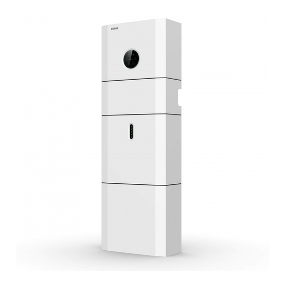
User Manual User Manual 1.7 System Appearance 1.7.1 Cable Box Part Figure 5 Inverter without Cable Box Covers– Front View Figure 4 BluE-H5/H3 Delivery Scope Object Descripition Hybrid Inverter EMS Display Screen Figure 6 Cable Box Part without Covers – Front View... -
Page 10: Liability Limitation
Places where salty and humid air can penetrate; 1.8 Liability Limitation Seismic areas - additional security measures are required; Any product damage or property loss caused by the following conditions, Kstar does not assume Sites with altitude below 2000m; any direct or indirect liability. -
Page 11: Installation
User Manual User Manual 2.2 Installation A H5/H3 installed in any corridor, hallway, lobby or the like and leading to an emergency exit shall ensure su cient clearance for safe egress of at least 1 meter. ffi Step 1 Remove the battery and inverter from the packaging box. The H5/H3 must also not be installed in potentially explosive atmospheres for gas cylinders that are heavier than air gases and have a vent clamp in accordance with AS / NZS 3000. - Page 12 User Manual User Manual 2.2.2 Inverter Installation NOTE: Step 6 Inverter Installation. The inverter's built-in residual-current monitoring unit (RCMU) removes DC residual current above 6mA, so an external RCD (type A) can be used with the system (≥30mA). NOTE: There is no temperature sensor port integrated in the machine. Step 4 Remove the debris ba e and secure the battery to the wall with screws and gaskets.
- Page 13 User Manual User Manual Step 8 Please make AC cables on site. d. Insert the crimped conductors L, N and PE into the corresponding terminals and tighten the screw with a hex key wrench screwdriver(size:2.5, 1.2~2.0 N.m). Ensure that all conductors Step 8-1 Please follow the AC cable requirements below.
- Page 14 User Manual User Manual (8) Use tool to clamp the AC wiring terminal and wire rod; screw the nut, but do not tighten it. Make sure that the cable is free to pass through the waterproof components. Once the terminal is connected to the right site of the inverter, tighten the nut. Figure 17 Cable Box Bottom View, Wiring Connectors Step 9 Take out the communication cable set provided in the accessory parts of one...
- Page 15 User Manual User Manual Step12 Close the battery covers and connect the PV-MC4 connectors to the system NOTE: (connection on both sides). Also, connect all AC cables, the meter communications Grounding protection: The inverter grounding protection terminal is permanently connected. cable METER, and the Ethernet cable LAN.
- Page 16 User Manual User Manual Step14 Open the front cover of the last battery and remove the DIP cover. Now set NOTE: the DIP switch 2 to "on" mode and close the cover again. The DIP setting is only changed on the last battery. If you connect more than 2 battery modules to the system, please only install the additional batteries 3~4 on the side of the system.
- Page 17 User Manual User Manual The electricity meter should be mounted and connected at the grid transition point DRED means demand response enable device. The AS/NZS 4777.2:2015 required inverter (feed-in point) so that it can measure the grid reference and feed-in power. need to support demand response mode(DRM).
-
Page 18: Earth Fault Alarm Connection
User Manual User Manual 2.5 Earth Fault Alarm Connection The BluE series inverter complies with IEC 62109-2 13.9. The fault indicator LED on the inverter cover will light up and the LCD screen will show an error code of F07 Normal Load indicating the earthing fault. -
Page 19: Wiring Diagram
User Manual User Manual 2.7 Wiring Diagram System Operation In accordance with Australian safety regulations, the neutral cables of the on-grid side and the back-up side must be connected together, otherwise the back-up function will 3.1 Switch On not work. When turning on the system, it is very important to follow the steps below to prevent damage to the system. -
Page 20: Switch Off
ff When the BluE-H5/H3 energy storage system appears to be running abnormally, you can turn off 2. If the battery pack is not on re yet, extinguish the re before the battery pack catches fi... -
Page 21: Display And Setting
User Manual User Manual 4.2. Display and Setting Object Description Name 4.2.1 PV1 input display interface Grid connection Interface O -grid ff Indicator LED PV1 INPUT Red: The inverter is in fault. PV1 input real-time voltage VOLT: 33.8V PV1 input real-time current Return Button: Escape from current CURR: 0.00A... - Page 22 User Manual User Manual 4.2.5 att ry Prmet r 4.2.9 Load Interface Interface BACKUP BATTERY PRMETER Battery type:(lead acid, lithium battery) Emergency load (BACKUP) voltage TYPE: LEAD-ACID VOLT: 0.00V Emergency load (BACKUP) current Battery temperature CURR: 0.00A TEMP: 0.0℃ Percentage of battery surplus capacity SOC: 4.2.10 Power Interface...
-
Page 23: Setting
User Manual User Manual 4. .13 Status information Description Interface Description Interface -USER- Press ESC on the Main Display Interface to enter →1 :SETUP the user interface. System information:Power-up mode, standby 2:INQUIRE See chapter 8.2 for more setting details. mode, hybrid grid-connection, o -grid operation, ff... - Page 24 User Manual User Manual 4.3.1 System setting 1.Self-consumption mode disables grid charging: --CHARGE TIME-- Battery pack can only be charged by PV. Description Interface 00:00-23:59 2.Self-consumption mode enables grid charging: Grid MAX SOC:100% This interface is used to access system charges battery pack until MAX SOC during set time.
- Page 25 User Manual User Manual ④DRM enable ⑨ GFCICHK ENB Description Description Interface Interface --DRM ENABLE-- GFCICHK ENB It is enabled when BACKUP load needs power. GFCICHK ENB(1. Disable Enable →1:DISABLE 1 DISABLE PV leakage protection enable Default option is disabling. →...
- Page 26 6:BluE–LEP grid power is positive "+",it means the CT connection Select the other selections enter button to enter the 7:KSTAR-LEP is reversed. If the CT direction is 1. POSITIVE on the restart interface. LCD, set it to 2. NEGATIVE, then the grid power will become negative "-".
- Page 27 User Manual User Manual Lead-acid battery parameter ④ Charge current Description Description Interface Interface Press UP/DOWN button to increase or decrease This interface is used to select other Li battery --CHARGE CURR-- --LEAD-ACID -- the input gure; fi parameter. Press Enter to move cursor backward, con rm input fi...
- Page 28 User Manual User Manual BAT WAKE-UP BMS DOD Description Description Interface Interface 1.Disable BMS DOD: It will not close the discharge --BMS DOD-- -- BAT WAKE-UP -- Enter the option 1 to enable or disable the function. circuit when BMS discharging to the set SOC. →1:DISABLE →1:ENABLE Enter the option 2 to adjust the value of the time.
- Page 29 User Manual User Manual 4.3.4 Operation parameters 4.3.3 Grid standard Description Interface Description Interface --RUN SETTING-- Press UP/DOWN button to move corresponding --GRID STD-- → 1:REACT POWER options. Here are eleven countries for selection, Press UP/DOWN button to move corresponding 2:GRID POWER →...
- Page 30 User Manual User Manual GRID VOLT MAX Description Description Interface GRID Over Voltage Protection Point -GRID MAX- Press UP/DOWN to adjust the input gure; fi INPUT: 270V Press Enter to con rm the input. fi ④Volt Min Description Interface ② Grid-connected power Interface Description -VOLT MIN-...
- Page 31 User Manual User Manual ⑤Freq Max Low INV frequency Description Description Interface Interface INV Low Frequency Protection Point -INV FREQ LOW- Press UP/DOWN to adjust the input gure; fi -FREQ MAX- Enter option 1 to adjust the maximum frequency of INPUT: Press Enter to con rm the input and enter restart fi...
- Page 32 User Manual User Manual OVER VOLT START OVER FREQ ENABL Description Interface Description Interface Press UP/DOWN to adjust the input gure; fi -OVER START- -OVER FREQ- Derate power when Frequency over. Press Enter to con rm the input. fi INPUT: 264V →1:DISABLE The default option is enable.
- Page 33 User Manual User Manual UNDER FERQ START 4.3.5 485 Address Description Interface Description Interface The function that the power of inverter derates -UNDER FERQ START- Press UP/DOWN button to adjust the input gure; fi -485 ADDRESS- when frequency is too low. Press UP/DOWN to Press ENTER button to con rm or ESC button to fi...
- Page 34 User Manual User Manual 4.3.9 Date/time 4. .13 Factory default setting Description Interface Description Interface Press UP/DOWN button to adjust the input gure; fi Press Enter button to move cursor backward, --DATE/TIME-- -FACTORY RESET- Press U P/DO N but to move correspondin con rm input and return to setup interface;...
-
Page 35: Inquiry
User Manual User Manual Description Description Interface Interface Threshold setting value: The value set by upper Threshold setting value: The value set by upper FACMIN(S1) VACMAX(S1) computer software. computer software. Threshold setting trip time: The trip time set by Set:49.8Hz 100ms Threshold setting trip time: The trip time set by Set:253.0V 603s upper computer software. - Page 36 User Manual User Manual ③ Firmware Version ⑥ Running records Description Interface Description Interface SN of the fault: Fault warning codes (500 at This interface displays rmware version for ARM fi --FIRMWARE-- --REC (170) -- 1:F10-1 utmost)(the latest fault or alarm marked as No.1) ARM VER:1.0.0 and DSP of the inverter;...
-
Page 37: Statistics 5
4.5 Statistics ④The day Description Interface Description Interface This interface is used to select statistics items; Press UP/DOWN button to move corresponding This interface displays power generation for the --E-TODAY-- options; --STAT-- day(kWh); 0.0KWH Press Enter to enter the selected menu; →1:TIME STAT. -
Page 38: Restart
User Manual User Manual ⑦ Gross generation Battery Storage and Recharging Description Interface 5.1 Battery storage requirements --E-TOTAL- 0.0KWH This interface displays gross power generation; 1. Storage environment requirements: METER: 0.0KWH PV power generation; –Ambient temperature: -10℃–45℃; recommended storage temperature: 20℃–30℃; GRID: 0.0KWH Electric energy selling to grid;... -
Page 39: Inspection Before Battery Recharging
User Manual User Manual 5.3 Inspection before battery recharging Stick Logger Quick Guide Before recharging a battery, check its appearance: Deformation/Shell damage/Leakage 6.1 Download APP 5.4 Recharge Operation Steps Step 1: Scan the QR Code on the right side and download the APP. Step 1:Connect power cables to the battery charger correctly. -
Page 40: Logger Status
User Manual User Manual 6.3 Logger Status READY 6.3.1 Check Indicator light Solution Fault Description Fault Cause READY Lights Implication Status Description(All lights are single green lights.) 1. Connection betw- 1.Check the connection between stick 1. Light o : Fail to connect to the router. ff... -
Page 41: Usage Methods And Notices For Reset Button
User Manual User Manual 6.5Usage Methods and Notices for Reset Button SOLARMAN Smart APP 6.5.1 Usage methods and key-press descriptions for reset button 7.1 Registration Key-press Status Description Light Status Go to SOLARMAN Smart and register. Click "Register" and create your account here. Short press 1s SMARTLINK rapid networking status. -
Page 42: Network Con Guration Fi
User Manual User Manual 7.4 Network Con guration fi Step 2:Connect to AP network Click "Go to connect" and nd the right "AP_XXXXX" network (XXXXX refers to logger fi After the logger is added, please con gure the network to ensure normal operation.Go fi... -
Page 43: Alarm Code And Error Code
User Manual User Manual 8.2 Error code Alarm Code and Error Code 8.1 Alarm code English description English description Codes Codes Grid Volt Low Soft Time Out Grid Volt High INV Volt Short Grid Frequency Low GFCI Sensor Fault Grid Frequency High Bus Volt Low Solar Loss Bus Volt High... -
Page 44: Fault Diagnosis And Solutions
User Manual User Manual Fault Diagnosis and Solutions Types Codes Solutions The inverter is easy to maintain. When you encounter the following problems, please (1) Check the input mode setting is correct. refer to the Solutions below, and contact the local distributor if the problem remains (2) Disconnect the PV input, restart the inverter and wait PV Input Short Circuit unsolved. -
Page 45: Machine Parameters
User Manual User Manual Types Codes Solutions (1) Check whether the installation follows the instructions; LN Reverse (2) Contact customer service if error warning continues. INV Abnormal (1) Please contact the distributor. (1) Restart the inverter and wait until it functions normally. (1) Restart the inverter and wait until it functions normally. - Page 46 User Manual User Manual Maximum continuous input current 32Aa.c. Weight (Kg) Maximum continuous input power 7360VA Dimension (W×H×D)mm 540* 0*240 540*1020*240 Rated output Current 16Aa.c. 22Aa.c. 16Aa.c. 22Aa.c. IP Protection IP65 Maximum continuous output current 16Aa.c. 22Aa.c. 16Aa.c. 22Aa.c. Warranty 5 Year Product Warranty, 10 Year Performance Warranty Power factor (Cos phi), adjustable 0.8 leading ~0.8 lagging...
- Page 47 User Manual User Manual Table 9.1 Grid speci cation (single-phase) fi Topology High Frequency Isolation Cooling Natural Convection Output Voltage Output Frequency Grid Boot wait time(S) Speci cation fi Range (Vac) Range (Hz) Display LCD/APP 187-252 48-50.5 China Communication Interface RS485/CAN2.0/WIFI 184-264 47.5-51.5...
-
Page 48: Routine Maintenance
User Manual User Manual Routine Maintenance 11.2 Notes After the equipment is out of operation, please pay attention to following notes while maintaining : 11.1 Maintenance Plan Related safety standards and speci cations should be followed in operation and fi Check if wire connections are loose. -
Page 49: Quality Assurance
Conditions • After replacement, unquali ed products shall be processed by KSTAR. fi • The customer shall give KSTAR or his partner a reasonable period to repair the faulty device. Exclusion of Liability In the following circumstances, KSTAR has the right to refuse to honor the quality guarantee: PV inverter industry Pre-sales:(86)0755-89741234 Ext 8151...
Need help?
Do you have a question about the BluE-H5 and is the answer not in the manual?
Questions and answers