Table of Contents
Advertisement
Quick Links
Advertisement
Table of Contents

Related Manuals for AQC MAXIREACH EBS-605


Summary of Contents for AQC MAXIREACH EBS-605
- Page 1 Owner’s manual for installation, use and maintenance This manual is property of the owner. Leave with the unit when set-up and start-up are complete. AQC Dust Collecting Systems inc. reserves the right to change design and specifications without prior notice.
-
Page 2: Table Of Contents
Pivoting Extension Boom INDEX Introduction . . . . . . . . . . . . . . . . . . . . . . . . . . . . . . . . . . . . . . . . . . . . . . . . . Information on the MAXIREACH extension swing boom . -
Page 3: Introduction
Pivoting Extension Boom 1 INTRODUCTION This present manual refers to the MAXIREACH extension single and double pivot swing boom. It includes important information concerning the installation, use and maintenance of your collector. Read this manual thoroughly and apply the directives and procedures. Staff and personnel using the system will have to trained on safety measures and maintenance instructions. WARNING! The use of the extension swing boom will require proper installation and handling. Contact A.Q.C. Inc. if you have any doubt in regard to the use of your extension swing boom. Not following directives and procedures could cause injuries or property damages. INFORMATION ON THE MAXIREACH EXTENSION SWING BOOM Model: Serial number: Delivery date: Date of installation: Name of customer: Address: Accessories: Other:... -
Page 4: Presentation
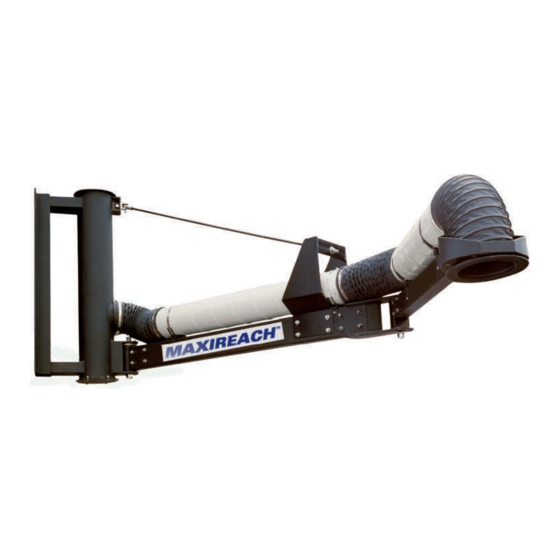
Pivoting Extension Boom 3 PRESENTATION Pivoting extension pivot swing booms are designed to extend the working area of local extraction devices. They make it possible to reach areas where impurities are being created with, for example, a self-supporting arm, flexible hoses, hose reels etc. Due to a wide range of reaches, the booms are especially useful for the extraction of dust or gas impurities from difficult to reach areas. Additionally the booms can be used to suspend other equipment such as welding wire feeders, hose reels etc. within the range of permissible loads. 3.1 Each MAXIREACH unit includes: • Boom base with wall/column support plates. • Horizontal painted steel tube(s) support. • Spiral ducting and flexible hose connections with hose clamps. • Companion flanges for fan or exhaust duct system. • Pull rod for purpose of boom to be level. • Friction disks with tension adjustment (on boom base pivot only). • Middle pivot (for double action swing boom). • 3 steps paint finish: degreasing, prime coat and polyurethane final coat. -
Page 5: Model Numbers
Pivoting Extension Boom 4 MODEL NUMBERS Weight Reach of work [feet] / [m] Ducting Mimimum Boom load [lbs] / Models diameter mounting Number capacity [kg] Numbers [inches] / height [feet] of pivots Total [lb] / [kg] whitout [mm] / [m] EBS-605 5 / 1.55 — 5 / 1.55 6 / 152 7.8 / 2.4 150 / 70 124 / 58 EBS-610 10 / 3.10 — 10 / 3.10 6 / 152 7.8 / 2.4 150 / 70 144 / 67 EBS-615... -
Page 6: Operation And Purpose
Pivoting Extension Boom The Maxireach swing boom is shipped partly assembled but requires minimal final field assembly. Because of carrier restrictions, swing The MAXIREACH swing boom is shipped partly assembled but requires minimal final field assembly. booms horizontal steel tubes longer than 10’ Because of carrier restrictions, swing booms horizontal steel tubes longer than 10' (3 meters) are (3 meters) are shipped in two (2) pieces. shipped in two (2) pieces. A joiner with fasteners is included for field assembly. -
Page 7: Components (Single And Double Pivot)
Pivoting Extension Boom 7 COMPONENTS (SINGLE AND DOUBLE PIVOT) 1. Boom base 2. Duct companion flange 3 . Boom base pivot joint 4. Boom base tie rod end support bracket 5. Boom base flexible hose 6. Ducting system spiral pipe 7. Horizontal steel tube support 8. Pull rod with tie rod end 9. Pull rod support bracket 10 . Middle pivot 11 . Flexible hose 12 . Ducting system spiral pipe 13 . Support beam made of square tubing with bracket to mount Maxair self-supporting arm 8 INSTALLATION WARNING! Installation of equipment must be performed as per local building laws and regulations. Structure must meet proper weight support of arm and equipment. -
Page 8: Inspection Of Goods
Pivoting Extension Boom 8.1 Inspection of goods The MAXIREACH swing is shipped partly assembled or in sections. Proceed with a visual inspection upon receiving the material and check for any apparent damage that may have occured on freight. Generally, shipment includes the boom base, horizontal tubes, spiral duct and flexible hose. Other optional components such as fume arms, hose reels or hose drops may be delivered on separate skids. 8.2 Location 1. The wall or column where the swing boom will be installed should be able to support the weight of such along with the accessories and / or attached equipment. Such support structure should be level for the swing boom to remain steady when not in use. 2. The span or reach of the swing boom should not be encumbered by overhead cranes, lighting, jigs or any other equipment. 3. Install the swing boom in a way to have access to the levelling pull rod, friction disks or any other equipment that may require scheduled maintenance. 4. If the swing boom is supplied with optional equipment, refer to the proper manual for installation and guidance. -
Page 9: Required Tools
Pivoting Extension Boom 9.1 Required tools The following tools and equipment are required for the assembly of the swing boom: • Crane or lift truck • Sockets • Chains • Power drill • Slings • Concrete drill bit • Shackles • Anchors • Eye bolts • Bolts • Spikes • Self tapping screws • Wrench Other tools may be required. It is advised to obtain services from a qualified contractor with appropriate equipment for proper installation. - Page 10 Pivoting Extension Boom 9.2.1 Assembly (first pivot) 3. Once the boom base is secured to support structure, align horizontal steel tube (#7) to pivot joint (#3) 17/425 boom base pivot support bracket. Remove friction disks (#10) and steel pin (#13) from boom base pivot 17/425 bracket. 4. Slide horizontal steel tube pivot section into boom base pivot bracket. NOTE: Do not attempt to remove 9/229 pivot bushings (# 12) from pivot joint. 5. Insert one (1) friction disk (#10) over the pivot section and one (1) under the pivot section. Insert steel pressure plate (#9) over the top friction disk, sandwiched between the friction disk and the boom...
-
Page 11: Connection Of Boom Base To Exhaust Ductwork
Pivoting Extension Boom 10 . Insert tie rod end section of pull rod into boom base pull rod support bracket and attach with fastener. Replace last nut and washer onto threaded end of pull rod. Note: At this point, do not try to adjust and level the horizontal support beam. Wait until optional equipment at end of swing boom has been installed. 11 . Using the hose clamps supplied, fasten flexible hose from spiral pipe section to boom base flexible hose flange. 9.2.2 Assembly (middle pivot, if ordered) 1. Remove friction disks and fasteners from horizontal steel tube middle pivot bracket. 2. Slide middle pivot assembly into pivot bracket. -
Page 12: Assembly Of Optional Equipment On Swing Boom
Pivoting Extension Boom 9.4 Assembly of optional equipment on swing boom 9 .4 .1 MAXAIR fume arm Refer to MAXAIR installation manual. 9 .5 MAXIDROP hose drop system Refer to MAXIDROP installation manual. BOOM LATERAL POSITIONNING CABLE AND HANDLE KIT 9 .6 MAXIREEL exhaust hose reels Note: The following MAXIDROP and MAXIREEL installation procedures should include a hanging cable with handle for lateral displacement of MAXIREACH extension swing boom. A.Q.C. usually supplies cable and handle. Contact factory or representative if piece is missing. -
Page 13: Maxidrive Exhaust Fans (Discard Duct Companion Flange For Direct Boom Base Fan Mount)
Pivoting Extension Boom 9 .7 MAXIDRIVE exhaust fans (discard duct companion flange for direct boom base fan mount) MAXIDRIVE fans can be installed on top or bottom of boom base. Direction of exhausted air has to be confirmed by customer or engineer. 1. Prior to installing the fan, ensure direction of ductwork connected to fan outlet will not come in direct contact with obstacles such as overhead cranes, light fixtures, etc. Usage of elbows or bends are allowed. 2. Install fan on boom base using the fasteners. Bolt pattern on 1HP fan inlet match 6" boom base flanges and 2HP fan inlet matches 8" boom base flange. 3. Connect exhaust ductwork to fan outlet. Note: if a 2HP fan (8" inlet) is used with a 6" diameter swing boom, installer will need to supply an offset bend such as drawing below in order for fan scroll to clear support wall or column. A.Q.C. may supply offset if specified. PULL ROD UNION WARNING! Refer to the Safety section prior to proceeding with any maintenance or inspection on the extension swing boom. 10. START UP 10.1 Check list 1. Move extension boom from right to left and ensure it does not "jerk". 2. Ensure extension boom does not "swing" excessively. 3. Ensure swing boom does not hit obstacles such as lights, columns, etc. 4. Ensure exhaust duct is sealed and installed properly. 5. Ensure all flexible hoses are clamped tight. -
Page 14: Maintenance And Inspection
Pivoting Extension Boom 11 MAINTENANCE AND INSPECTION The chart indicated below shows different inspections and the frequency at which they should be performed. Frequency of Components Procedures inspections Move extension boom left and right and ensure Pivot joints boom moves in desired location. Daily Push extension boom up and down. Ensure there is Support base no excessive "play" in movement. Ensure hose clamps are secured. Weekly Flexible hoses Check for cracks or tears in fabric. Replace if necessary. Check sturdiness of support base installation. Yearly All components Check wear on pivot friction discs and steel pins. Check all welds. 12 TROUBLESHOOTING Problem Probable cause Solution Boom base not level Ajust level on boom base. Extension boom does not stay in place Friction discs worn out Replace friction disks. Tear or hole in Replace flexible hose. flexible hose fabric Insufficient suction of dust or smoke... -
Page 15: Warranty
Pivoting Extension Boom 13 WARRANTY Coverage: Aireau Quality Control Inc. or its designated affiliate (the "Seller") selling the product 13.1 (the "Product"), warrants that the Product sold by Seller will be free from defects in material and workmanship for a period of 12 months from the date of its installation or 14 months from the date of shipment by Seller, whichever date is earlier (the "Warranty Period"). Exceptions: This warranty does not apply to any Product or portion thereof that: (i) has been used 13.2 in a manner not in compliance with Seller’s or manufacturer’s documentation and instructions, (ii) has had changes, alterations or repairs made by a person other than a person authorized by Seller, (iii) has been improperly installed or used or has been installed or used contrary to applicable codes, standards, laws and regulations, (iv) has been subjected to improper storage, accident, neglect, misuse or abuse, (v) has been damaged during shipping, (vi) has been subject to damages resulting from normal wear and tear, (vii) has not been used with appropriate fire protection systems or explosion venting when required or (viii) has not been installed by a licensed contractor with experience in fire and explosion hazards and applicable codes, laws and regulations . For greater certainty, this warranty does not apply to filters sold as part of, or for use with, the Product. Unless specifically accepted otherwise in writing by Seller, Seller does not warrant that electrical equipment will comply with any laws or regulations of the customer’s jurisdiction. Claims: To benefit from this warranty, customer must notify Seller in writing of the Product defect, 13.3 which notice shall include a reasonable description of the defect, within 10 days from the date such defect is discovered or ought to have been discovered. Remedy: During the Warranty Period and subject to the terms herein, Seller will, at its option, 13.4 either: (i) repair or replace the Product or any defective parts or components (except for filters) with Product, parts or components (except filters) free from defect or (ii) credit or refund the purchase price of the Product. If Seller so requests, customer must return the defective Product to Seller’s place of business determined by Seller. Shipping, installation, removal and re-installation costs will be solely borne by the customer. The foregoing shall be customer’s sole and exclusive remedy for any defect in the product, its parts and components and for any breach of the warranty herein. Disclaimer: Except as set forth in this section 1, each of seller, its affiliates and their directors, 13.5 officers, subcontractors and representatives (the "seller parties") disclaims all representations... -
Page 16: Limitation Of Liability
Pivoting Extension Boom 14 LIMITATION OF LIABILITY 14.1 Limitation of Liability: Notwithstanding anything to the contrary, in no event will the seller parties’ liability arising out of, or related to, the product or its parts and components, whether pursuant to contractual or extracontractual liability, tort or under any other theory of liability, exceed the price paid to seller for the product giving rise to such liability. 14.2 Exclusion of Consequential and Similar Damages: Notwithstanding anything to the contrary, in no event will the seller part ies be liable for any indirect, punitive, special, exemplary, incidental, consequential or other similar damages of any type or kind (including loss of revenue, profits, use or other economic advantage, damages due to product failure, work stoppage or delays in delivery) arising out of, or in any way connected to, the product or its use, breach of contract, tort (including negligence), strict liability, product liability, or otherwise, regardless of cause, even if the seller parties had previously been advised of the possibility of such damages or could have reasonably foreseen them. Fire and Explosion and Acceptance of Risk: Customer acknowledges that improper installation 14.3 or use of the Product may result in fire or explosion. To minimize such risks, proper installation, operation, and maintenance of the Product in accordance with all applicable codes, standards, laws and regulations is critical. Prior to installation and use, customer shall ensure that the Product meets the applicable codes, laws and regulations, including those related to the addition of appropriate fire protection systems or explosion venting. Installation shall be performed by a licensed contractor with experience in fire and explosion and applicable codes, laws and regulations.
Need help?
Do you have a question about the MAXIREACH EBS-605 and is the answer not in the manual?
Questions and answers