Table of Contents
Advertisement
Quick Links
Advertisement
Table of Contents

Related Manuals for AQC MAXAIR


Summary of Contents for AQC MAXAIR
- Page 1 Owner’s manual for installation, use and maintenance This manual is property of the owner. Leave with the unit when set-up and start-up are complete. AQC Dust Collecting Systems inc. reserves the right to change design and specifications without prior notice.
-
Page 2: Table Of Contents
9.1 MAXAIR typical installations ........ -
Page 3: Introduction
Fume Arms 1 INTRODUCTION This present manual refers to the MAXAIR source capture fume arm. It includes important information concerning the installation, use and maintenance of your unit. Read this manual thoroughly and apply the directives and procedures. Staff and personnel using the system should be trained on safety measures and maintenance instructions. -
Page 4: Presentation
The MAXAIR fume arm is a system designed to be positioned near the area where fume, smoke, dust or any pollutant is being produced. The fume arm (also sometimes called snorkel) is an effective system to remove harmful pollutants from the worker’s breathing zone. MAXAIR capture arms are not a guarantee that all the fumes or smoke will be captured in the section hood. Hood positionning is important to usure collection. Main applications include welding, buffing, pharmaceutical operations, handling of volatile dusts, harmful vapours, etc. -
Page 5: Model Numbers
Fume Arms 4 MODEL NUMBERS 4.1 Hanging or table / bench mount Stainless Standard Optional Stainless Arm Bench steel Arm length hood hood Weight Hanging steel diameter mount bench ft / m diameter diameter lbs / kg hanging in / mm mount in / mm in / mm FA-HPG3-03 FA-PPG3-03 FA-HSS3-03 FA-PSS3-03 3 / 7 6 3 ... -
Page 6: Normal Use
Fume Arms 5 NORMAL USE The MAXAIR fume arm is designed to remove dust and smoke from the air resulting from a manufacturing process. Each MAXAIR fume arm is built as per the criteria and information supplied by the customer for a specific application and should not serve any other application without the approval of AQC inc. PINCH POINT PINCH POINT WARNING! MAXAIR 3" and 4" fume arms have pinch points at top and middle joints. DO NOT PLACE FINGERS OR HANDS AT PINCH POINTS WHEN MOVING THE ARM INTO DESIRED POSITION. -
Page 7: Components
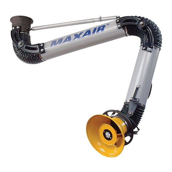
Fume Arms 7 COMPONENTS 7 .1 MAXAIR main components (hanging version) 1. Socket set assembly 2. Flexible hose (typ. of 3) 3 . Socket tube 4. Hood tube 5. Damper handle 6. Connectors for hood movement (typ. of 4) 7. Joint wheel 8. Capture hood 9. Hood grab handle 10 . -
Page 8: Maxair Main Components (Bench Mount / Portable Version)
Fume Arms 7 .2 MAXAIR main components (bench mount / portable version) 1 . Socket set assembly 2. Flexible hose (typ. of 3) 3. Socket tube 4. Hood tube 5. Damper handle 6. Connectors for hood movement (typ. of 4) 7. Joint wheel 8. Capture hood 9. Hood grab handle... -
Page 9: Maxair Main Components (Telescopic Version)
Fume Arms 7 .3 MAXAIR main components (telescopic version) 1 . Socket set assembly 2 . Flexible hose (typ. of 2) 3 . Socket tube (fixed) 4. Hood tube (sliding, twist and lock) 5. Damper handle 6. Connectors for hood movement (typ. of 4) 7 . Joint wheel 8. -
Page 10: Installation
Fume Arms 8 INSTALLATION The MAXAIR fume arm is designed to remove dust and smoke from the air resulting from a manufacturing process. Each MAXAIR fume arm is built as per the criteria and information supplied by the customer for a specific application and should not serve any other application without the approval of AQC inc. WARNING! Installation of equipment must be performed as per local building laws and regulations. Structure must meet proper weight support of arm and equipment. Wall support must be securely bolted to the wall, see page 15. -
Page 11: Arm And Wall/Post Bracket Installation (Hanging Type, No Exhaust Fan)
If the arm bracket is installed on a wall or a column, ensure the "tooth" is facing the wall or the column. 3" and 4" arms are able to rotate 360 degrees and do not have a stopper. 3 . Lift MAXAIR fume arm into position and align both arm and bracket bolt patterns. 4 . Using the fasteners provided, attach the arm onto the support bracket. Ensure the duct flange is centered with the bracket oultet. Before proceeding to the next step, push the arm left and then right to ensure the socket rotates freely. - Page 12 Fume Arms 5. To attach the spring telescopic assembly, push the arm UP until the eyelet on the spring assembly meets with the male socket spring bracket. Insert eyelet in spring bracket and attach with fasteners provided. ATTACH SPRING HERE SPRING STOPPER LIFT TUBE TO ATTACH SPRING ASSEMBLY 6. Arm joints are partly adjusted at the factory and will need final adjustment prior to usage. Using two (2) adjustable wrenches, tighten all joints starting from the top left and top right. One wrench will hold the nylon insert lock not and the other wrench will hold the head of the bolt. Begin with only half turns alternating left and right until arm holds it’s position and does not sag. Proceed with left and right middle joints. End with all four (4) adjustable joints at hood section.
-
Page 13: Arm And Ceiling Bracket Installation (Hanging Type)
Fume Arms 8.4 Arm and ceiling bracket installation (hanging type) The installation crew must ensure the arm/bracket assembly is installed within the arm reach for the area where source capture has to be performed. The arm bracket must be installed to ceiling trusses or joists or any other structure capable of supporting weight of the arm and optional equipment. 1. Install bracket on support structure according to arm length. Fasteners to support structure are not supplied. Arm bracket can also be welded to structure if allowed or permitted. Proceed with steps 3 to 7 in arm hanging type installation procedures. 8.5 Arm and bracket installation (hanging type with exhaust fan) Note : This type of installation will not require the duct flange. -
Page 14: Arm And Bracket Installation (Hanging Type With Exhaust Fan)
3. Connect exhaust ductwork (and silencer if supplied) to fan outlet. COMPANION DUCT FLANGE 9 OPTIONAL EQUIPMENT The MAXAIR fume arm is offered with options as follows: 1. Direct mount exhaust fan 2. LED 24V light kit with switch 3. 24V hood mounted fan switch 4 . 24 V transformer for light or fan switch 5. Oversized hoods (shipped unassembled to fume arm) -
Page 15: Maxair Typical Installations
Fume Arms 9.1 MAXAIR typical installations. Other installations are possible. Contact AQC or your representative for details. MAXAIR (hanging model, wall or post) MAXAIR (portable or table/bench with bracket only. mount) with bracket. SUPPORT BRACKET FUME ARM SUPPORT BRACKET FUME ARM Note on bench mount models : Do not force arm down at socket past the maximum bend. This may cause damages in the spring and cable assembly in socket. - Page 16 Fume Arms MAXAIR (hanging model, wall or post) MAXAIR (hanging model) with exhaust fan and support bracket. with ceiling bracket. EXHAUST FAN CEILING BRACKET Note : a flanged reducer will be required if bracket and arm are not of same EXHAUST DUCTWORK diameters. ex : 1 hp 6"...
- Page 17 Fume Arms MAXAIR (hanging model, wall or post) MAXAIR (hanging model) with exhaust fan and support bracket. with vertical floor post EXHAUST DUCTWORK CONNECTION DUCTWORK FAN SUPPORT BRACKET MAXIREACH-BD VERTICAL FLOOR POST SPACER (IF NECESSARY) SUPPLIED BY OTHER FUME ARM No QTÉ Description Bride à...
-
Page 18: Start Up
Note : Light kit and fan switch operate on 24 A.C. 25' (7.7 meters) of low voltage cable is supplied. Light kits and fan switches are factory installed on the fume arm hoods when ordered with such. Field installation is also possible. AQC will supply instruction procedure if light kit or fan switch is ordered once the fume arm is installed. 1. Wire set 2. LED light 24VAC/35W 3. O-ring seal... -
Page 19: Electrical Connections
Fume Arms 12 ELECTRICAL CONNECTIONS The electrical connection diagrams shown below are the most common supplied by AQC Special or customized panels are available. Contact your representitive for details. 12.1 MAXAIR single phase fan starter (without light kit) MECHANICAL RESET OPTION FXX OPTION SUPPLY MTR1 MOTOR 1 PH 60 HZ L2 / N Adjust according to the table 1: VOLT Adjust according to the table 2 or 3 Adjust according to the table 1: OL... -
Page 20: Maxair Single Phase Fan Starter (With Light Kit)
Fume Arms 12.3 MAXAIR single phase fan starter (with light kit) MECHANICAL RESET OPTION FXX OPTION SUPPLY MTR1 MOTOR 1 PH 60 HZ L2 / N Adjust according to the table 1: VOLT Adjust according to the table 2 or 3 Adjust according to the table 1: OL... -
Page 21: Maintenance And Inspection
Fume Arms 13 MAINTENANCE AND INSPECTION The chart indicated below shows different inspections and the frequency at which they should be performed. Frequency of Components Procedures inspections Ensure arm stays in desired position for source capture. Arm joints, socket Open and close air damper to ensure proper Daily and damper operation. Move arm left and right. Ensure no grinding or squeeking is heard or felt. Check for possible leaks or tears. Repair or replace if necessary. Weekly Flexible hoses Ensure hose clamps are fastened correctly. -
Page 22: Troubleshooting
Fume Arms 14 TROUBLESHOOTING Problem Probable cause Solution Joints are loose Adjust the joints (tighten). Friction disks are worn Fume arm sags Replace friction disks. (will not stay in place) Spring assembly is Replace spring assembly. broken or too loose Fan rotates the wrong If supplied (reverse phases). Vacuum damper is Open damper. -
Page 23: Warranty
Fume Arms 15 WARRANTY Coverage: Aireau Quality Control Inc. or its designated affiliate (the "Seller") selling the product 15.1 (the "Product"), warrants that the Product sold by Seller will be free from defects in material and workmanship for a period of 12 months from the date of its installation or 14 months from the date of shipment by Seller, whichever date is earlier (the "Warranty Period"). Exceptions: This warranty does not apply to any Product or portion thereof that: (i) has been used 15.2 in a manner not in compliance with Seller’s or manufacturer’s documentation and instructions, (ii) has had changes, alterations or repairs made by a person other than a person authorized by Seller, (iii) has been improperly installed or used or has been installed or used contrary to applicable codes, standards, laws and regulations, (iv) has been subjected to improper storage, accident, neglect, misuse or abuse, (v) has been damaged during shipping, (vi) has been subject to damages resulting from normal wear and tear, (vii) has not been used with appropriate fire protection systems or explosion venting when required or (viii) has not been installed by a licensed contractor with experience in fire and explosion hazards and applicable codes, laws and regulations . For... -
Page 24: Limitation Of Liability
Fume Arms 16 LIMITATION OF LIABILITY 16.1 Limitation of Liability: Notwithstanding anything to the contrary, in no event will the seller parties’ liability arising out of, or related to, the product or its parts and components, whether pursuant to contractual or extracontractual liability, tort or under any other theory of liability, exceed the price paid to seller for the product giving rise to such liability. 16.2 Exclusion of Consequential and Similar Damages: Notwithstanding anything to the contrary, in no event will the seller part ies be liable for any indirect, punitive, special, exemplary, incidental, consequential or other similar damages of any type or kind (including loss of revenue, profits, use or other economic advantage, damages due to product failure, work stoppage or delays in delivery) arising out of, or in any way connected to, the product or its use, breach of contract, tort (including negligence), strict liability, product liability, or otherwise, regardless of cause, even if the seller parties had previously been advised of the possibility of such damages or could have reasonably foreseen them. Fire and Explosion and Acceptance of Risk: Customer acknowledges that improper installation 16.3 or use of the Product may result in fire or explosion. To minimize such risks, proper installation, operation, and maintenance of the Product in accordance with all applicable codes, standards, laws and regulations is critical. Prior to installation and use, customer shall ensure that the Product meets the applicable codes, laws and regulations, including those related to the addition of appropriate fire protection systems or explosion venting. Installation shall be performed by a licensed contractor with experience in fire and explosion and applicable codes, laws and regulations.
Need help?
Do you have a question about the MAXAIR and is the answer not in the manual?
Questions and answers