Table of Contents
Advertisement
Quick Links
Owner's manual for installation,
use and maintenance
2MCH2-8, 2MCH3-12, 2MCH4-16, 3MCH2-12, 3MCH3-18, 3MCH4-24, 4MCH2-16, 4MCH3-24,
4MCH4-36, 5MCH4-40, 6MCH4-48, 7MCH4-56, 8MCH4-64, 9MCH4-72, 10MCH4-80
This manual is property of the owner. Leave with the unit when set-up and start-up are complete.
AQC Dust Collecting Systems inc. reserves the right to change design and specifications without prior notice.
Advertisement
Table of Contents

Related Manuals for AQC Maxiflo 2MCH2-8


Summary of Contents for AQC Maxiflo 2MCH2-8
- Page 1 4MCH4-36, 5MCH4-40, 6MCH4-48, 7MCH4-56, 8MCH4-64, 9MCH4-72, 10MCH4-80 This manual is property of the owner. Leave with the unit when set-up and start-up are complete. AQC Dust Collecting Systems inc. reserves the right to change design and specifications without prior notice.
-
Page 2: Table Of Contents
Horizontal downflow pleated cartridge dust collector INDEX Introduction . . . . . . . . . . . . . . . . . . . . . . . . . . . . . . . . . . . . . . . . . . . . . . . . . Information on the dust collector . -
Page 3: Introduction
Horizontal downflow pleated cartridge dust collector INTRODUCTION This present manual refers to the MAXIFLO dust collector equipped with an air pulse cleaning system. It includes important information concerning the installation, use and maintenance of your collector. Read this manual thoroughly and apply the directives and procedures. Staff and personnel using the system should be to trained on safety measures and maintenance procedures. WARNING! The type of dust to be filtered may require an explosion relief venting system. Dust collectors are not equipped with such a device unless it was requested when ordered. Contact A.Q.C. Inc. if you have any doubt in regard to the use of your collector. Not following directives and procedures could cause injuries or property damages. INFORMATION ON THE DUST COLLECTOR Model: Serial number: Delivery date: Date of installation: Name of customer: Address: Accessories: Other:... -
Page 4: Presentation
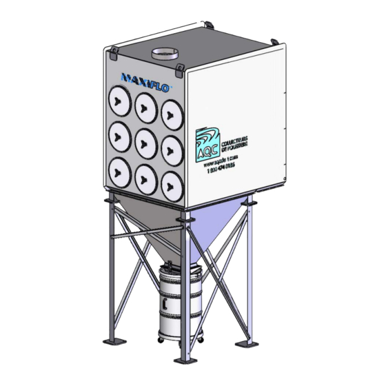
Horizontal downflow pleated cartridge dust collector PRESENTATION The MAXIFLO is a cartridge dust collector with an air pulse cleaning system which cleans the entire surface of filtration. The down flow type dust collector obtains high efficiency filtration while requiring low energy consumption. The cartridges are cleaned by means of a sequenced pulse of compressed air and this, one at a time. The MAXIFLO dust collector is largely used in areas where dust is a nuisance. Main applications are for welding, buffing, pharmaceutical operations, handling of volatile dusts, etc. The MAXIFLO may offer multiple configurations for dust capture. Optional equipment may include a hopper with quick clip drum, drawer or with conveyor and rotary valve. 3.1 Each MAXIFLO unit includes: • Fully welded steel cabinet with reinforcements. • 4 to 80 filter cartridges with specific media for your application. • Air deflectors to protect the cartridges from larges debris. • Cartridge cleaning system by air pulsation and electronic sequencer. • Factory prewired cleaning valves. •... -
Page 5: Operation
Horizontal downflow pleated cartridge dust collector WARNING! Flammable or explosive dusts and solvents present a fire or explosion hazard within the collector. Under no circumstances, those pollutants should be filtered by the collector unless it has been designed to that effect and equipped with an explosion relief venting system or fire extinguishing device. This is the reason why special attention is required with the handling of dust collecting equipment in contact with flammable or explosive dusts and solvents. Any burning or flammable material such as a spark created by metal grinding, lit cigarettes, spark, etc. should not be introduced within the collector where it could cause a fire or explosion. OPERATION During normal operation, the MAXIFLO unit vacuums dust laden air into the collector inlet. Smaller particles are vacuumed toward the cartridges and larger particles fall toward the dust storage section. Dust is trapped within the cartridge leaving clean air crossing the filter toward the collector outlet. 5.1 Cartridge cleaning The cleaning of the filter cartridges is performed using a reverse air pulse technology (see figure 1). A solenoid and diaphragm valve system is aligned toward the cartridges and the shock wave created by releasing air at high velocity cleans the cartridges. The cleaning cycle starts from the upper cartridges and ends at the lower cartridges. -
Page 6: Installation
2. Wind factor and seismic zones should be considered before selecting the location of the dust collector. 3. Position the dust collector in a way to have access to the control panel, cleaning valves, pneumatic conduits, access door to filters and dust storage systems as suggested in figure 2. 4. If the dust collector is equipped with an explosion relief venting system, follow guidelines for its location. 5. Fume arm may also be duct mounted. If so, ducting must be able to support weight of arm combined with push and pull effects of moving the arm for source capture postion. 6. The MAXAIR fume arm may also be used with optional AQC equipment such as extension swing booms, sliding rail with trolley, portable filtration units, etc. Refer to appropriate manual for installation. Figure 2 RECOMMENDED FREE/WORK SPACE Recommended free/work space Drawing # 2... -
Page 7: Assembly
Horizontal downflow pleated cartridge dust collector ASSEMBLY 7.1 Required tools The following tools and equipment are required for the assembly of the dust collector: • Crane or lift truck • Sockets • Spreader • Power drill • Chains • Concrete drill bit • Slings • Concrete anchors • Shackles • Bolts • Eye bolts • Self tapping screws. • Spikes • Caulking • Wrench ASSEMBLY 1. Prepare the area where the collector will be installed making sure it is clear and free of any obstacle. -
Page 8: Structure Assembly
outline. One strip should be applied inward of the bo Horizontal downflow pleated cartridge dust collector strip outward of the bolt holes (Figure 4). 5. Lift the filter cabinet using the lift lugs. Using spikes, position above the dust storage section making sure to align the cabin 6 . - Page 9 dust storage bolt holes. Horizontal downflow pleated cartridge dust collector WARNING he use of a spreader is recommended to avoid amages to the filter cabinet. 1. Vertically install the outer support legs. 2. Install the cross braces with the hardware supplied as shown in figure 3. One is installed inside of the legs and the other outside of the legs. Do not tighten the screws at this moment. e filter cabinet onto the dust storage section and align the bolt holes. 3. With the use of a crane (or lifting device), slowly set the hopper onto the support plates.
-
Page 10: Electrical Connection
Horizontal downflow pleated cartridge dust collector ELECTRICAL CONNECTION WARNING! The electrical connections must be executed by a qualified electrician and with respect to codes and regulations. For safety measures, shut off power supply to the collector prior to perform the installation. Lock off any power supply prior to servicing or maintenance. The dust collector control panel regulates the cartridge cleaning system. The dust collector control panel may be installed on the MAXIFLO unit, inside or outside the building or remote of the unit. 1. Using the electrical diagram supplied with the panel, connect the power supply from the main breaker (supplied by the customer) to the control panel. 2. Refer to the descriptive identification plate to select proper voltage and amperage. 3. If the unit is supplied with a customized control panel, refer to the descriptive schematics to perform connection to the power supply. 4. Verify for proper motor rotation. -
Page 11: Electrical Connection For Dct-1000 Sequencer
Horizontal downflow pleated cartridge dust collector Figure 5 TYPICAL CONNECTION FOR DCT-500 SERIES ELECTRONIC BOARD Typical connection for DCT-500 series electronic board Drawing # 5 10.2 Electrical connection for DCT-1000 sequencer The MAXIFLO dust collector is equipped with 115V solenoids which activate the cleaning valves. These solenoids are grouped in a NEMA 4 ½ panel installed behind the cabinet, above the air tanks. A differential control panel (DCP) may also be included on the electronic panel. Wiring for these solenoids is factory assembled. The optional DCT-1000 activates the solenoids in sequence to operate the cleaning valves. Drawing # 6 represents a typical connection with a starter to a DCT- 1000 sequencer card. The electronic panel is activated in simultaneously with the fan start-up. This operation will regulates the pulses required as per the status of the filters. - Page 12 Horizontal downflow pleated cartridge dust collector 10.2.1 DCT-1000 board specifications DCT-1000 controller: Number of connectors: 6, 10 & 22 Extendable to 255 connections by using extension card DCT-1122 & DCT-1110 Power: 85-270 VAC, 50-60 Hz. Consumption: 5 W. Power to solenoids: 3A max per connection. Fuses: 3 A @ 250 VAC. Temperature range: -40 to 140°F (-40 to 60°C). Shutter time: 10 msec to 600 msec. Shutter time accuracy: ±10 msec. Down time: 1 second to 255 seconds Down time accuracy: ±1% of setting Weight: 1 lb, 3.0 oz (538.6 g). Approval agency: UL, cUL. DCP pressure module: DCP PRESSURE MODULE Pressure range: 10"w.c. ou 20"w.c. Temperature range: -40 to 140°F (-40 to 60°C) High pressure: 10 psig (68.95 kPa). High pressure (differential): 10 psig (68.95 kPa) Accuracy: ±1.5% F.S. @ 73°F (22.8°C). Outlet signal: 4-20 mA. Weight: 5.5 oz (155.9 g). PNEUMATIC CONNECTIONS STARTER FUSES FOR DIFFERENTIAL PRESSURE NEMA 4/12 ENCLOSURE HP MOTOR CONTROLLER...
-
Page 13: Compressed Air Connection
Horizontal downflow pleated cartridge dust collector 10.3 Compressed air connection WARNING! Compressed air must be free of oil and humidity. Contamination of compressed air may result in a poor cartridge filtration, decreased cleaning and reduced life time. Purge the compressed air line to remove any debris prior to connecting air line to the dust collector air tank. Shut off the compressed air system and purge all air lines prior to servicing or maintaining the collector. Locate the pneumatic air tank(s) behind the MAXIFLO dust collector. Connect air line to the tank(s) using pipe seal. Check for possible leak(s). Note : The use of an air dryer is strongly recommended to avoid any problems related to humidity in the compressed air system. Install a shut off valve, pressure regulator and filter on the compressed air line. Those components are not supplied by A.Q.C. unless required by the customer. All components must meet a maximum 90 psig pressure. NEVER ALLOW MORE THAN 100 PSIG. Damages to components may occur. 10.4 Ventilation ducting 1. The dust collector should be installed as close as possible to the source of dust in order to... -
Page 14: Electrical Connections
Horizontal downflow pleated cartridge dust collector ELECTRICAL CONNECTIONS 12.1 Check list Prior to starting the collector for the first time, the check list must be followed to ensure a proper continuous operation. 1 . Remove all objects in and around the inlet and outlet. 2. Check if all accessories and optional equipment are installed correctly. 3. Ensure the compressed air gauge indicates 90 psig. Check for air leaks. 12.2 Electrical connections WARNING! The electrical connection must be executed by a qualified electrician and with respect to codes and regulations. For safety measures, shut off power supply to the collector prior to perform the installation. 1. Ensure all electrical connections sealed and power is available. 2. Check remote control connections (if any) and that all breakers are OFF. 3. Switch ON power to the unit. 4. Start the fan and shut off immediately. Check fan rotation. The rotation is indicated on the label of the fan. 5. Adjust the adequate air volume using the air damper (if any) at the fan outlet. Note : An excessive air volume may shorten the life expectancy of the cartridges or cause an electrical power surge on the fan and the system. 12.3 Optional equipment RAMP... -
Page 15: Anti-Abrasive Inlet
Horizontal downflow pleated cartridge dust collector Follow these steps to remove the drum from the collector: 1. Hold up the drum 2. Unlock the quick clip system 3. Lower drum onto the ramp slides 4 . Slide drum slowly toward you WARNING! Do not let drum fall free while unlocking the quick clip system. Be careful when releasing clip. Follow these steps to install the drum back into position: 1. Ensure the flange gasket seal is in place and intact. Replace if damaged. 2. Slide the drum into the ramp slides. 3. Check to make sure the drum flange is pushed at the end of the slide. 4. Lift drum up. 5. Attach the drum to the quick clip system 6 . Check the seal assembly. Adjust quick clip system if there is a leak. 12.4 Anti-abrasive inlet This option is recommended for the filtration of abrasive particles which may damage the filter elements. A highly resistant steel plate slows down the particles and make them less abrasive on the filters. DIRTY AIR INLET DUST COLLECTOR CONNECTION ABRASION PLATE... -
Page 16: Platform And Ladder
Horizontal downflow pleated cartridge dust collector 12.5 Platform and ladder Platforms and ladders are available for 8 to 80 cartridges MAXIFLO units. They may be stationary or attached to the dust collector structure. Contact an A.Q.C Inc. Representative to know which platform design is best suited to your needs. Instructions for platform and ladder assembly are included on delivery. WARNING! Ensure platform and ladder are correctly installed before climbing on the platform. 12.4 Explosion relief vent Note on explosion venting panels : a minimum clearance of 25' (8 meters) free of obstacles, pedestrian walkway, building walls, trees or bushes is required to allow dispersion of possible blast. Contact factory for details. A.Q.C. Inc. will not be held liable nor responsible for any injury or damage caused by fire or explosion as per the agreement issued upon construction of the dust collector. However, the explosion relief vent is designed to meet NFPA-68 criteria, related to explosion venting systems. The entire venting surface is calculated using such criteria. The explosion venting panel is domed and is certified ATEX. Pstat is 0.1 bar (1.45 psi) + ou - 15% @ 71.6 F, KST max is 500 bar m/s. Pmax < 1.8 bar (26 psi). Max vacuum - 80 WG and made from 304L stainless steel. WARNING! The explosion vent must point in a direction away from workers area, offices, pedestrian walkways or any other area usually accessible, vegetation or any matter that would sustain damages caused by an explosion. A deflector shield... -
Page 17: Magnehelic Gauge
Horizontal downflow pleated cartridge dust collector MAGNEHELIC GAUGE The Magnehelic is a differential pressure gauge used to measure the difference between the clean and dirty air. This allows a visual reference on the filters status and indicates when it is time to replace. This gauge is generally factory installed unless under specific request to A.Q.C.. If the Magnehelic gauge is not part of the collector, connect the (HIGH-PRESSURE) tube on the "dirty" side of the collector. Connect the other (LOW-PRESSURE) tube on the "clean" side of the collector. This gauge is not available when the collector is supplied with a DCT-1000 electronic board and a DCP pressure module since it is this one that will read the pressure differential. START/STOP PROCEDURE 14.1 Start up with new filters Shut 50% off all inlet and outlet dampers (if any) before starting the unit. This procedure is mostly helpful when the dust to be filtered sticks to the filter surface. Do not operate the filtration system until the pressure differential has increased by at least 1" w.g. from the starting point. This operation allows "caking" onto the cartridges for a better filtration efficiency. 14.2 Regular start up Ensure all optional equipment (i.e. screw conveyor, rotary valves, etc.) except the blower are... -
Page 18: Electrical Components
Horizontal downflow pleated cartridge dust collector Workers must wear protective clothing and apparatus such as safety goggles, gloves, respiratory equipment, etc. when working inside the collector. Instructions in this booklet must be read and understood prior to performing tasks on the collector. 15.2 Electrical components All electrical components must be shut down and main breaker locked to avoid any possible risk of electrocution when handling or working on such components. 15.3 Explosive dusts If the dust to be collected is naturally explosive or inflammable once inside the collector, an explosion relief venting system and/or a fire extinguishing device will be required. If you have any doubt as to the nature of the dust to be collected, call your A.Q.C. representative. 15.4 Anchors All sections of the dust collector including the optional equipment must be bolted to the slab in order for the unit to be stable and secured should an explosion occur or in case of high winds. 15.5 Interior installation When a dust collector equipped with an explosion relief venting system is installed inside the premises, the unit must be installed within 3 meters (10 feet) of an exterior wall and the explosion vents has to be connected to an exhaust duct leading outside. This duct must be designed to sustain the same pressure as the one within the dust collector. -
Page 19: Maintenance
Horizontal downflow pleated cartridge dust collector MAINTENANCE WARNING! Refer to the Safety section prior to proceeding with any maintenance or inspection on the dust collector. A preventive maintenance program should dismiss most emergency shut downs and extend the expected life time of the system. The charts contained in this chapter explain the maintenance operations and procedures in case of problems with the system. The schedules and delays in between operations may be modified with conclusive experiments or with a specific usage of the collector. If you have any questions, do not hesitate to call an A.Q.C. Inc. representative. 16.1 Remplacement of cartridges The filtering cartridges life expectancy is only limited to it’s resistance to the dust to be filtered which in most cases does not require periodic changes. However, if a cartridge should tear or be punctured, replacement of such should be performed as soon as possible. 16.2 Remplacement of cartridges Prior to changing the cartridges, shut down the blower(s), screw conveyor(s), rotary valve(s), control panel(s) and any other adjacent equipment. Lock all related breakers in the electrical panels. Shut down and bleed the compressed air line feeding the collector. Maintenance staff must wear protective goggles and an adequate respiratory apparatus. Purge the system of all gazes and vapours other than air. Ensure the air flow is shut off and that the interior temperature is at a safe level. - Page 20 Horizontal downflow pleated cartridge dust collector 1. Remove the cartridge round access door by unscrewing the knob. Ensure that you do not damage the rubber gasket seal around the access door. Start this procedure from the top row of cartridges. 2. Remove the nut and washer from the yoke’s threaded rod. Set them aside. 3. Slowly twist the cartridge half a turn to remove the deposit of dust that could be on top of the cartridge. 4. Gently slide out the cartridge along the yoke. Repeat steps 3 and 4 if it is a modle with two (2) cartridges deep. 5. Disposal of dirty cartridges must be done according to environmental regulations. 6. Check for any excessive dust accumulation in the hopper and clean if necessary. Follow these steps to install the new cartridges. Note : older type MAXIFLO dust collectors are equipped with open/open and open/closed type cartridges. More recent type MAXIFLO dust collectors are equipped with open/open and open/ open type cartridges. Ensure you order the proper type of cartridges for replacement. Ensure that you have the same cartridges as originally installed in the collector. 1. Slide the cartridges onto the yokes starting the open/open type. Check for the integrity of the cartridge seal. 2. Install the washer and nut that you set aside earlier. Screw in the assembly for a proper seal. 3. Install the access door back onto the cabinet making sure the rubber gasket seal is well attached. Screw the knob in and asses all components are sealed. 4 . Switch power and compressed air system back on before starting the unit.
-
Page 21: Compressed Air System
Horizontal downflow pleated cartridge dust collector COMPRESSED AIR SYSTEM WARNING! Shut off the compressed air valve and bleed the line feeding the collector prior to performing maintenance on the unit. 1. Periodically check the compressed air components such as the air dryer and regulator. Replace in line air filters feeding compressed air to the unit. 2. Remove any humidity that may be present in the compressed air lines using the recommendations of the manufacturer. -
Page 22: Programming Instructions
Horizontal downflow pleated cartridge dust collector PROGRAMMING INSTRUCTIONS 18.1 DCT-500 sequencer The card programming was factory adjusted. The valves opening time is set at 100 msec and the delay between each opening is set at 10 seconds. Should those delays be modified for any reason, adjust the potentiometers located at the top of the electronic board. "PULSE ON" represents the opening time and the "PULSE OFF" represents the delay in between each cleaning sequence. Refer to the manufacturer’s owner’s manual for any questions concerning the DCT-500 sequencer. Note: Do not readjust the valves opening time "PULSE ON" or the delay between each cleaning until appropriate tests have been made. A too short or too long delay could reduce the life expectancy of the filters. Contact your A.Q.C. representative for questions. 18.2 DCT-1000 sequencer The card programming was set at the factory. The valves opening time was set at 100 msec and the delay set at 10 seconds. Furthermore, if the electronic card was supplied with a pressure module, other parameters may be programmed such as low and high pressures, pulse connectors, etc. Should those delays be modified for any reason, adjust them as per the following instructions: Press the "select" button to scroll the different programming options. Press "UP" and "DOWN" buttons to modify the value. 1. "LAST OUTPUT" sets the amount of valves the system uses. 2. "TIME OFF" sets the delay in between each pulse. 3. -
Page 23: Maintenance And Inspection
Horizontal downflow pleated cartridge dust collector MAINTENANCE AND INSPECTION The chart indicated below shows different inspections and the frequency at which they should be performed. Frequency of Components Procedures inspections Check the clean air outlet for possible presence of dust or smoke traces. Check the level of dust in the storage bins or drums. Dust collector Empty if needed. Daily Check the proper operation of the diaphragm valves. Magnehelic gauge Check and log data. If the values indicated are above the fixed limits, refer to the troubleshooting section. Check for possible leaks. Repair if necessary. Ensure the cartridges are well sealed. Weekly Filters Look for accumulation of dust or debris above and inside the filters. Clean if necessary. Perform a complete inspection of the collector and its components. Check the status of the cartridges and the filtration efficiency. Replace if necessary. -
Page 24: Troubleshooting
Horizontal downflow pleated cartridge dust collector TROUBLESHOOTING Problem Probable cause Solution Check installation of cartridges and repair if necessary. Cartridges are not Seal the whole assembly (Refer to the replacement installed correctly. cartridge section on page 2). Cartridges are Screw in tight in order to have the gaskets squeezed not adjusted against the frame. Dust or smoke at the clean air outlet Cartridges are da- Replace defective filters (Refer to the replacement maged cartridge section on page 2). Check the gaskets on the access doors, honeycomb Gaskets are damaged plate, and on the filters. Fan rotates the wrong Check rotation of fan. Access doors are not Check all access doors and gaskets. Also check hopper properly sealed for leaks. Check for obstructions at the fan outlet. Remove Fan has obstructions any debris. Adjust the air damper. Remove and replace the used cartridges with the same Cartridges need to type of cartridges. (Refer to cartridges replacement... - Page 25 Horizontal downflow pleated cartridge dust collector Problem Probable cause Solution Check if voltage output to the sequencer is sufficient. Insufficient The sequencer card Check and replace the fuse if required. If voltage and suction of dust. does not respond fuse are working and card still does not respond, change the card. (refer to card connection on page 2). Check if voltage output to the card is sufficient. Check Air pulse cleaning and replace fuse if required (refer to card connection is insufficient. diagram on page 2). Shortage of Ensure there is a minimal 90 psig in the system. compressed air (Refer to eletrical connection on page 2). Lock all electrical breakers hooked up to the dust col- lector and bleed the pneumatic lines. Check for debris, wear and tear or a break in the diaphragm valve by Valves do not work removing the cover. Check for leaks at the solenoids properly and on the pneumatic hoses. Replace and repair all da- mages. If the valves are frozen, check the air dryer or install a heating element around the valves. Filtration has minimal effect. Wrong adjustment in Check for cleaning delay and duration are adequate.
- Page 26 Horizontal downflow pleated cartridge dust collector Problem Probable cause Solution Solenoids are not Check wiring between sequencer card and solemoids. wired properly Cleaning cycle light is ON but nothing happens. Defective solenoids Check if solenoids work properly. Cleaning cycle light Defective sequencer Check if sequencer card is defective by following is ON but nothing card the manufacturer’s recommendations. happens. Alarmvalue is too low Adjust to a higher value. The alarm light is Too much Check and clean compressed air system. Replace car- ON (DCT-1000) pressure loss tridges if normal pressure does not resume to normal. The pneumatic data Check the pneumatic hoses connected to the DCP hose is unplugged, pressure module for any leak or tear. broken or clogged.
-
Page 27: Warranty
Horizontal downflow pleated cartridge dust collector WARRANTY Coverage: Aireau Quality Control Inc. or its designated affiliate (the "Seller") selling the product 21.1 (the "Product"), warrants that the Product sold by Seller will be free from defects in material and workmanship for a period of 12 months from the date of its installation or 14 months from the date of shipment by Seller, whichever date is earlier (the "Warranty Period"). Exceptions: This warranty does not apply to any Product or portion thereof that: (i) has been used 21.2 in a manner not in compliance with Seller’s or manufacturer’s documentation and instructions, (ii) has had changes, alterations or repairs made by a person other than a person authorized by Seller, (iii) has been improperly installed or used or has been installed or used contrary to applicable codes, standards, laws and regulations, (iv) has been subjected to improper storage, accident, neglect, misuse or abuse, (v) has been damaged during shipping, (vi) has been subject to damages resulting from normal wear and tear, (vii) has not been used with appropriate fire protection systems or explosion venting when required or (viii) has not been installed by a licensed contractor with experience in fire and explosion hazards and applicable codes, laws and regulations . For greater certainty, this warranty does not apply to filters sold as part of, or for use with, the Product. Unless specifically accepted otherwise in writing by Seller, Seller does not warrant that electrical equipment will comply with any laws or regulations of the customer’s jurisdiction. Claims: To benefit from this warranty, customer must notify Seller in writing of the Product defect, 21.3 which notice shall include a reasonable description of the defect, within 10 days from the date such defect is discovered or ought to have been discovered. Remedy: During the Warranty Period and subject to the terms herein, Seller will, at its option, 21.4 either: (i) repair or replace the Product or any defective parts or components (except for filters) with Product, parts or components (except filters) free from defect or (ii) credit or refund the purchase price of the Product. If Seller so requests, customer must return the defective Product to Seller’s place of business determined by Seller. Shipping, installation, removal and re-installation costs will be solely borne by the customer. The foregoing shall be customer’s sole and exclusive remedy for any defect in the product, its parts and components and for any breach of the warranty herein. -
Page 28: Limitation Of Liability
Horizontal downflow pleated cartridge dust collector LIMITATION OF LIABILITY 22.1 Limitation of Liability: Notwithstanding anything to the contrary, in no event will the seller parties’ liability arising out of, or related to, the product or its parts and components, whether pursuant to contractual or extracontractual liability, tort or under any other theory of liability, exceed the price paid to seller for the product giving rise to such liability. Exclusion of Consequential and Similar Damages: Notwithstanding anything to the contrary, in 22.2 no event will the seller part ies be liable for any indirect, punitive, special, exemplary, incidental, consequential or other similar damages of any type or kind (including loss of revenue, profits, use or other economic advantage, damages due to product failure, work stoppage or delays in delivery) arising out of, or in any way connected to, the product or its use, breach of contract, tort (including negligence), strict liability, product liability, or otherwise, regardless of cause, even if the seller parties had previously been advised of the possibility of such damages or could have reasonably foreseen them. Fire and Explosion and Acceptance of Risk: Customer acknowledges that improper installation 22.3 or use of the Product may result in fire or explosion. To minimize such risks, proper installation, operation, and maintenance of the Product in accordance with all applicable codes, standards, laws...
Need help?
Do you have a question about the Maxiflo 2MCH2-8 and is the answer not in the manual?
Questions and answers