Table of Contents
Advertisement
Quick Links
Advertisement
Table of Contents

Related Manuals for VC VC2028


Summary of Contents for VC VC2028
- Page 1 Vision Components The Smart Camera People Hardware Documentation VC20XX Smart Cameras VC2028,VC2038, VC2038/E, VC2048/E,VC2065, VC2065/E, VC2065/C, VC2065/EC, VC2066, VC2066/E VC2068, VC2068/E Revision 1.1, February 2005 Document name: VC20XX_HW.pdf © Vision Components GmbH Ettlingen, Germany...
- Page 2 VC20XX_HW.pdf – Hardware Documentation VC20XX Smart Cameras Foreword and Disclaimer This documentation has been prepared with most possible care. However Vision Components GmbH does not take any liability for possible errors. In the interest of progress, Vision Components GmbH reserves the right to perform technical changes without further notice. Please notify support@vision-components.com if you become aware of any errors in this manual or if...
-
Page 3: Table Of Contents
Pin Assignment for the I/O Plug Pin Assignment for the RS232 (V24) Pin Assignment LAN/Ethernet Pin Assignment for the XGA/SVGA Video Output Technical Specifications VC20XX Smart Cameras Technical Specifications VC2028 Technical Specifications VC2038 Technical Specifications VC2038/E Technical Specifications VC2048/E Technical Specifications VC2065... - Page 4 Connecting a compatible PC with a 9-pin D sub plug Connecting the Ethernet Cable Connecting the VC keypad Connecting the external trigger Connecting the external trigger and the VC keypad CE Compliance of VC20XX Smart Cameras CE Declaration of Compliance Programming...
-
Page 5: General Information
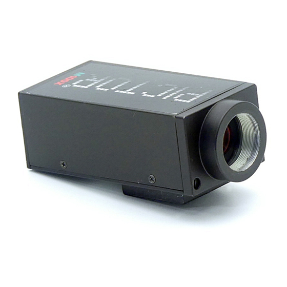
VC20XX_HW.pdf – Hardware Documentation VC20XX Smart Cameras 1 General Information The VC20xx Series smart cameras are compact, light-weight black-and-white or color video cameras with video memory and an image processor. They integrate a high-resolution CCD sensor with one of the fastest 32 bit image-processing signal processors (TMS320C6211). -
Page 6: Overview Camera Types
Low speed shutter up to 10 seconds Programmable gain and offset 24V Power Supply The following table shows the different features of each camera model: VC2038 VC2065 V2065C VC2066 VC2068 VC20XX SELECTION VC2028 VC2048E TABLE VC2038E VC2065E VC2065CE VC2066E VC2068E Sony 1/3" Progressive Scan CCD640x480 pixel Kodak 1/3"... - Page 7 (optional) Size: 110x50x36mm+foot/ Weight: 488g 1) The use of the VC2028 is recommended for imaging static (non moving) objects only. 2) If ordering a camera with Ethernet interface please add the suffix "/E" to the camera name (i.e. VC38/E, VC2065/EC).
-
Page 8: Basic Structure
VC20XX_HW.pdf – Hardware Documentation VC20XX Smart Cameras 2 Basic Structure The image is formed by a high-resolution progressive scan CCD sensor. One or two channels of video output are digitized. An input lookup-table is available for basic pixel-preprocessing. The image is stored in SDRAM memory using one of the 16 DMA channels (EDMA). -
Page 9: Boards
DAC board C6DAC SVGA quality video output with graphics memory, video capture, interfaces (RS232, etc.) Power board C6PWR Power supply, PLC interfaces 3.1 Sensor Boards Camera Type Sensor Board VC2028 C6SEN084 VC2038 C6SEN084 VC2038/E C6SEN084 VC2048/E C6SEN311 VC2065 C6SEN415 VC2065/E... -
Page 10: C6Sen084
VC20XX_HW.pdf – Hardware Documentation VC20XX Smart Cameras 3.1.1 C6SEN084 This board takes the picture. It is used in the VC2028, VC2038 and VC2038/E The CCD sensor 1/3" SONY ICX424AL (B/W) is used. The board controls the CCD sensor and processes the analog signal. -
Page 11: C6Sen205
VC20XX_HW.pdf – Hardware Documentation VC20XX Smart Cameras For the exact setting of the configuration, refer to the description of the configuration program in the software documentation. 3.1.3 C6SEN205 This board takes the picture. It is used in the VC2068 and VC2068/E The CCD sensor ICX205AL (B/W) is used. -
Page 12: C6Sen415
VC20XX_HW.pdf – Hardware Documentation VC20XX Smart Cameras The diverse features of this board (high-speed and low-speed shutter, external trigger, etc.) are configured via software. For the exact setting of the configuration, refer to the description of the configuration program in the software documentation. -
Page 13: Dac Board
2 independent LUTs for graphics and overlay, 8bit overlay mask register • 3x8bit video D/A (SVGA output) • UART and driver for RS232 (Ethernet versions : Ethernet PHY) • UART receiver for VC Keypad (9600 baud) • Trigger In/Out signals • PLC communication interface •... -
Page 14: Power Board
VC20XX_HW.pdf – Hardware Documentation VC20XX Smart Cameras The technical specifications for the SVGA output signals : Horizontal frequency: 45.072 kHz VBP: 32 lines Vertical frequency: 67.68 Hz VFP: 46 lines Resolution SVGA: 600x800 HSYNC width: 120 pixels Resolution eff. hor.: HBP: 94 pixels Resolution eff. -
Page 15: Plc I/O Signals
VC20XX_HW.pdf – Hardware Documentation VC20XX Smart Cameras 4 PLC I/O Signals The camera has four optically decoupled inputs and four decoupled outputs for controlling machines and processes. An I/O processor is responsible for the handling of the PLC I/O signals. The PLC-compatible inputs (24-V level, the positive signal is connected) include input protection circuits. -
Page 16: Output Signals
VC20XX_HW.pdf – Hardware Documentation VC20XX Smart Cameras 4.2 Output Signals Operating voltage: 24 V +/- 20%, external source Absolute maximum voltage: voltages greater than 40 V can destroy the outputs Type: galvanically separated by MOSFET optocouplers Switching voltage: positive switching Current: max. - Page 17 VC20XX_HW.pdf – Hardware Documentation VC20XX Smart Cameras Technical data of trigger output: output voltage: max. 7V output current: max. 50mA pull-up resistor: none, external resistor required © 1996-2005 Vision Components GmbH Ettlingen, Germany...
-
Page 18: Camera Plug Assignments
VC20XX_HW.pdf – Hardware Documentation VC20XX Smart Cameras 5 Camera Plug Assignments The cameras have four connectors on the rear side: RS232(V24) or HR10A-7R-6PB 6-pin Hirose plug pin contact 100MBd Ethernet Trigger / Keypad HR10A-7R-6SB 6-pin Hirose plug jack contact SXGA/SVGA/Video HR10A-10R-10SB 10-pin Hirose plug jack contact DC IN/PLC-I/O... -
Page 19: Pin Assignment For The Rs232 (V24)
VC20XX_HW.pdf – Hardware Documentation VC20XX Smart Cameras 5.3 Pin Assignment for the RS232 (V24) Rear view: (pin) Signal V24 RTS V24 TxD V24 GND NC V24 V24 CTS 5.4 Pin Assignment LAN/Ethernet Rear view: (pin) Signal 5.5 Pin Assignment for the XGA/SVGA Video Output rear view (jack): Signal G GND... -
Page 20: Technical Specifications Vc20Xx Smart Cameras
RGB, 3x75 Ohm, 1 Vpp, SVGA output, HSYNC, VSYNC separate Horizontal frequency: 45.072 kHz Vertical frequency: 67.68 Hz Resolution SVGA: 600x800 Pixel frequency: 46.875 MHz Use VC2038 instead of VC2028 for imaging moving objects. © 1996-2005 Vision Components GmbH Ettlingen, Germany... -
Page 21: Technical Specifications Vc2038
VC20XX_HW.pdf – Hardware Documentation VC20XX Smart Cameras 6.2 Technical Specifications VC2038 Sensor: 1/3" SONY ICX424AL eff. no. of pixels: 640(H) x 480(V) Pixel size: 7.4(H) x 7.4(V) µm Chip size: 5.79(H) x 4.89(V) mm High-speed shutter: 30,80,... microseconds in steps of 50 microseconds (full- frame shutter) Low-speed shutter: up to 20 sec. - Page 22 VC20XX_HW.pdf – Hardware Documentation VC20XX Smart Cameras Chip size: 5.79(H) x 4.89(V) mm High-speed shutter: 30,80,... microseconds in steps of 50 microseconds (full- frame shutter) Low-speed shutter: up to 20 sec. adjustable integration time Integration: full-frame Picture taking: without delay, program-controlled or triggered externally; full-frame / 40 frames per second Clamping: zero offset digital clamping...
-
Page 23: Technical Specifications Vc2048/E
VC20XX_HW.pdf – Hardware Documentation VC20XX Smart Cameras 6.4 Technical Specifications VC2048/E Sensor: 1/2" KODAK KAI-0330D eff. no. of pixels: 640(H) x 480(V) Pixel size: 9(H) x 9(V) µm Chip size: 7.3(H) x 5.52(V) mm High-speed shutter: 18,36,72, microseconds in steps of 36 microseconds (full- frame shutter) Low-speed shutter: up to 20 sec. -
Page 24: Technical Specifications Vc2065
VC20XX_HW.pdf – Hardware Documentation VC20XX Smart Cameras 6.5 Technical Specifications VC2065 Sensor: 1/2" SONY ICX415AL eff. no. of pixels: 782(H) x 582(V) Pixel size: 8.3(H) x 8.3(V) µm Chip size: 7.48(H) x 6.15(V) mm High-speed shutter: 5,10,15,20, microseconds in steps of 40 microseconds (full-frame shutter) Low-speed shutter: up to 20 sec. -
Page 25: Technical Specifications Vc2065/C
VC20XX_HW.pdf – Hardware Documentation VC20XX Smart Cameras 6.6 Technical Specifications VC2065/C Sensor: 1/2" SONY ICX415AK color sensor eff. no. of pixels: 782(H) x 582(V) Pixel size: 8.3(H) x 8.3(V) µm Chip size: 7.48(H) x 6.15(V) mm High-speed shutter: 5,10,15,20, microseconds in steps of 40 microseconds (full-frame shutter) Low-speed shutter: up to 20 sec. -
Page 26: Technical Specifications Vc2065/E
VC20XX_HW.pdf – Hardware Documentation VC20XX Smart Cameras Technical Specifications VC2065/E Sensor: 1/2" SONY ICX415AL eff. no. of pixels: 782(H) x 582(V) Pixel size: 8.3(H) x 8.3(V) µm Chip size: 7.48(H) x 6.15(V) mm High-speed shutter: 5,10,15,20, microseconds in steps of 40 microseconds (full-frame shutter) Low-speed shutter: up to 20 sec. -
Page 27: Technical Specifications Vc2065/Ec
VC20XX_HW.pdf – Hardware Documentation VC20XX Smart Cameras 6.8 Technical Specifications VC2065/EC Sensor: 1/2" SONY ICX415AK color sensor eff. no. of pixels: 782(H) x 582(V) Pixel size: 8.3(H) x 8.3(V) µm Chip size: 7.48(H) x 6.15(V) mm High-speed shutter: 5,10,15,20, microseconds in steps of 40 microseconds (full-frame shutter) Low-speed shutter: up to 20 sec. -
Page 28: Technical Specifications Vc2066
VC20XX_HW.pdf – Hardware Documentation VC20XX Smart Cameras 6.9 Technical Specifications VC2066 Sensor: 1/3" SONY ICX204AL eff. no. of pixels: 1024(H) x 768(V) Pixel size: 4.65(H) x 4.65(V) µm Chip size: 5.8(H) x 4.92(V) mm High-speed shutter: 10,20,30,45 µsec, then steps of 78 µsec (full-frame shutter) Low-speed shutter: up to 20 sec. -
Page 29: Technical Specifications Vc2066/E
VC20XX_HW.pdf – Hardware Documentation VC20XX Smart Cameras 6.10 Technical Specifications VC2066/E Sensor: 1/3" SONY ICX204AL eff. no. of pixels: 1024(H) x 768(V) Pixel size: 4.65(H) x 4.65(V) µm Chip size: 5.8(H) x 4.92(V) mm High-speed shutter: 10,20,30,45 microseconds, longer in steps of 78 microseconds (full-frame shutter) Low-speed shutter: up to 20 sec. -
Page 30: Technical Specifications Vc2068
VC20XX_HW.pdf – Hardware Documentation VC20XX Smart Cameras 6.11 Technical Specifications VC2068 Sensor: 1/2" SONY ICX205AL eff. no. of pixels: 1280(H) x 1024(V) Pixel size: 4.65(H) x 4.65(V) µm Chip size: 7.60mm (H) 6.20mm (V) High-speed shutter: 9,17,26,33, .. µsec, then steps of 69 µsec (full-frame shutter) Low-speed shutter: up to 20 sec. -
Page 31: Technical Specifications Vc2068/E
VC20XX_HW.pdf – Hardware Documentation VC20XX Smart Cameras 6.12 Technical Specifications VC2068/E Sensor: 1/2" SONY ICX205AL eff. no. of pixels: 1280(H) x 1024(V) Pixel size: 4.65(H) x 4.65(V) µm Chip size: 7.60mm (H) 6.20mm (V) High-speed shutter: 9,17,26,33, .. µsec, then steps of 69 µsec (full-frame shutter) Low-speed shutter: up to 20 sec. -
Page 32: Accessories
Power adapter for rail mounting • VC Keypad C6 • Y-cable Please refer to the VC website for the correct order numbers under: “Products -> Hardware -> VC20XX Smart Cameras -> Accessories VC20XX Smart Cameras” 7.1 Trigger Cable Length: 5m Signal Pin Nr. -
Page 33: Ethernet Patch Cable
VC20XX_HW.pdf – Hardware Documentation VC20XX Smart Cameras 7.3 Ethernet patch cable Signal Pin (to cam.) Pin (to PC) Cable Color Cable Color 20m patch cable 10m patch cable yellow white/pink orange pink white/green white/green green green 7.4 Power / PLC Cable Length: 5m Signal Pin No. -
Page 34: Power Adapter
Output Voltage DC 24V +/-5%, max. 300 mA (7.5 W) Equipped with connecting clamps for AC input and 24V output, CE certified 7.8 VC Keypad C6 VC Keypad includes the following keys: 4 cursor keys, Esc, Return, F1, F2 keys TTL version, 3m cable equipped with 6 pin Hirose connector. -
Page 35: Connecting The Camera
Connecting the VC keypad • Connecting the external trigger Also consult the “VC20XX Installation Manual” available on the VC Website under: “Support -> Customer Download Area -> Getting Started VC20XX Smart Cameras …” 8.1 Connecting the camera power Power must be connected to the 12pin I/O connector. Note, that the voltage is 24V. -
Page 36: Dual Voltage, With Or Without Plc Signals, Shutdown
VC20XX_HW.pdf – Hardware Documentation VC20XX Smart Cameras 8.1.2 Dual voltage, with or without PLC signals, shutdown Signal Pin No. color connect to 24V IN Cam red/blue 24V backup supply 24V PLC 24V power supply 24V PLC blue/pink 24V power supply GND IN com. -
Page 37: Connecting The Rs232 Interface
8.4 Connecting the VC keypad The VC keypad C6 can be connected directly to the Trigger/Keypad ("Trig.") Plug. Please order the 5V version (VC keypad C6) of the keypad. For details see : VC Keypad C6 © 1996-2005 Vision Components GmbH Ettlingen, Germany... -
Page 38: Connecting The External Trigger
VC20XX_HW.pdf – Hardware Documentation VC20XX Smart Cameras The RS232 version of the keypad is NOT compatible see Connecting the external trigger and the VC keypad 8.5 Connecting the external trigger Connect the external trigger input/output directly to the Trigger/Keypad ("Trig.") Plug. -
Page 39: Ce Compliance Of Vc20Xx Smart Cameras
Unfortunately, it is not possible to limit the question of electromagnetic compatibility to just one device or component. The entire system must always be considered. Thus, the accessories such as cables, power supplies, etc., play a significant role for the VC series cameras. - Page 40 VC20XX_HW.pdf – Hardware Documentation VC20XX Smart Cameras for the manufacturer Vision Components Ottostr. 2 76275 Ettlingen Karlsruhe, 01.11.2003 .......... (legal signature) Enclosures: schematic diagrams mechanical drawings (outside dimensions) Records of tests conducted by the certified test laboratory © 1996-2005 Vision Components GmbH Ettlingen, Germany...
-
Page 41: Programming
The following libraries and aids are also available: Real-time operating system for VC cameras with control of video I/O signals, control of serial interface and of PLC I/O signals, file management system for flash EPROM and Multi Media Card. -
Page 42: Appendix A: Blockdiagram Vc20Xx Smart Cameras
VC20XX_HW.pdf – Hardware Documentation VC20XX Smart Cameras Appendix A: Blockdiagram VC20XX Smart Cameras © 1996-2005 Vision Components GmbH Ettlingen, Germany... -
Page 43: Appendix B: Housing Dimensions Vc20Xx Smart Cameras
VC20XX_HW.pdf – Hardware Documentation VC20XX Smart Cameras Appendix B: Housing Dimensions VC20XX Smart Cameras The housing of the VC2048 has 15mm deep cooling fins left and right of the camera body, making it 80mm wide. © 1996-2005 Vision Components GmbH Ettlingen, Germany... -
Page 44: Appendix C: Spectral Transmission Of Ir Filter
VC20XX_HW.pdf – Hardware Documentation VC20XX Smart Cameras Appendix C: Spectral Transmission of IR Filter Note: This IR cut filter is incorporated in every VC20XX camera. The IR filter can be removed if required without loosing Vision Component’s manufacturers warranty. In this case, special care must be taken not to damage the CCD sensor. -
Page 45: Index
Plug Assignment ........15 VC Keypad..........36 technical specifications CPU Board ............8 overview ............ 16 DAC Board ............9 Technical Specifications I/O-Plug VC2028 ............. 16 Plug Assignment ........14 VC2038 ............. 18 Input Signals..........11 VC2038/E ..........19 Keypad VC2048/E ..........20 Plug Assignment ........14 VC2065/EC .......... - Page 46 VC20XX_HW.pdf – Hardware Documentation VC20XX Smart Cameras Trigger ............12 Technical Specifications......24 Input ............12 VC2066 Output ............12 Technical Specifications......25 Plug Assignment ........14 VC2066/E VC2028 Technical Specifications......26 Technical Specifications ......16 VC2068 VC2038 Technical Specifications......27 Technical Specifications ......18 VC2068/E VC2038/E Technical Specifications......
Need help?
Do you have a question about the VC2028 and is the answer not in the manual?
Questions and answers