Sign In
Upload
Download
Table of Contents
Contents
Add to my manuals
Delete from my manuals
Share
URL of this page:
HTML Link:
Bookmark this page
Add
Manual will be automatically added to "My Manuals"
Print this page
×
Bookmark added
×
Added to my manuals
Manuals
Brands
VC Manuals
Digital Camera
7210
Operating manual
VC 7210 Operating Manual
Smart camera
Hide thumbs
1
2
Table Of Contents
3
4
5
6
7
8
9
10
11
12
13
14
15
16
17
18
19
20
21
22
23
24
25
26
27
28
29
30
31
32
33
34
page
of
34
Go
/
34
Contents
Table of Contents
Bookmarks
Table of Contents
Table of Contents
1 General Information
2 Technical Specifications VC72XX
Technical Specifications VC7210
Technical Specifications VC7211
Technical Specifications VC7215
Technical Specifications VC7222
Technical Specifications VC7224
3 VC72XX Camera Interfaces
LAN / Ethernet Interface
Pin Assignments LAN / Ethernet Interface
Available Accessories for LAN / Ethernet Socket
Trigger & Serial (RS232) Interface
Pin Assignments Trigger & Serial (RS232) Interface
Trigger Cable
Serial (RS232) Cable
Y-Cable
Electrical Specifications of Trigger & Serial (RS232) Interface
Power Supply and IO Interface
Pin Assignments Power Supply and IO Interface
Electrical Specifications Camera Power Supply Camera
Electrical Specifications Digital PLC IO Interface
Available Accessories / Cables for Power Supply and IO Interface
4 Order Numbers Cameras and Accessories
Order Numbers of All Available VC72XX Camera Models
Order Numbers of All Available VC72XX Accessories
5 Programming VC72XX Smart Cameras
General Settings
Compiling and Linking with the VC72XX Cameras
Image Acquisition
Appendix A: Block Diagram VC72XX Smart Cameras
Appendix B: Dimensions VC72XX
Appendix C: Drawing Camera Head VC72XX
Appendix D: Spectral Transmission of IR Filter
Advertisement
Quick Links
1
Technical Specifications Vc7210
Download this manual
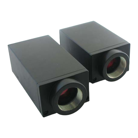
Components
The Smart Camera People
VC72XX Operating Manual
Hardware Specifications and special Software Functions of
Revision 1.5 – 27 Jan 2016
Document name: VC72XX_HW.pdf
Vision Components GmbH Ettlingen, Germany
Vision
VC72XX Smart Cameras
®
®
Table of
Contents
Previous
Page
Next
Page
1
2
3
4
5
Advertisement
Table of Contents
Need help?
Do you have a question about the 7210 and is the answer not in the manual?
Ask a question
Questions and answers
Related Manuals for VC 7210
Digital Camera VC 7215 Operating Manual
Smart camera (34 pages)
Digital Camera VC MIPI OV9281 How To Set Up
On a raspberry pi model 3b+ (13 pages)
Digital Camera VC VC2028 Manual
Smart cameras (46 pages)
Digital Camera VC VCSBC6438 Operating Manual
Vcsbc64 series smart cameras (39 pages)
This manual is also suitable for:
7211
7215
7222
7224
Table of Contents
Print
Rename the bookmark
Delete bookmark?
Delete from my manuals?
Login
Sign In
OR
Sign in with Facebook
Sign in with Google
Upload manual
Upload from disk
Upload from URL


Need help?
Do you have a question about the 7210 and is the answer not in the manual?
Questions and answers