HP Vectra VL600 Technical Reference Manual
Hp vectra vl600: reference manual
Hide thumbs
Also See for Vectra VL600:
- Supplementary manual (138 pages) ,
- User manual (74 pages) ,
- Installation manual (32 pages)
Table of Contents
Advertisement
Advertisement
Table of Contents

Related Manuals for HP Vectra VL600


Summary of Contents for HP Vectra VL600
- Page 1 Technical Reference Manual Product Description - Vectra VL600 This technical reference and BIOS document for Vectra VL600 PCs contains summary information only. More detailed information on system hardware is available in the Technical Reference Manual - Vectra Technology. HP Vectra VL600 PCs...
-
Page 3: Table Of Contents
VL600 Desktop ........ - Page 4 BIOS Summary ......... . . Using the HP Setup Program ........
-
Page 5: About This Document
About this Document This technical reference and BIOS document for Vectra VL600 PCs contains summary information only. More detailed information on system hardware is available in the Technical Reference Manual - Vectra Technology. VL600 Bibliography HP Vectra VL600 (D8610-90001) User’s Guides manual... -
Page 7: System Overview
System Overview This chapter introduces the internal and external features, and lists the specifications of the HP Vectra VL600 PC models. -
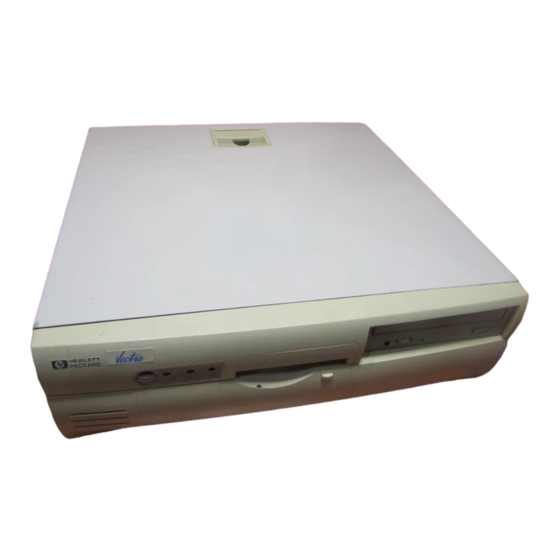
Page 8: Package Features
1 System Overview Package Features Package Features VL600 Desktop Power on Front view Status Light (flashes in sleep mode) Power On/ Off Button Front view with cover removed Expansion card slots System board switches Processor Main memory Floppy disk drive... -
Page 9: Rear Connectors
1 System Overview Package Features Rear view Voltage selection switch Monitor Rear connectors Parallel Port Mouse Keyboard Line In Serial Ports A & B Speaker Microphone... -
Page 10: Vl600 Minitower
1 System Overview Package Features VL600 Minitower Front view Power On/ Off Button Power On Status Light (flashes in sleep mode) Keyboard Lo ck Status Light Hard Disk Drive Activity Light Rear view Voltage selection switch Monitor Front view with cover removed Main Memory... -
Page 11: Specifications
Specifications Physical Characteristics VL600 Desktop Weight (excluding display and keyboard) Dimensions Footprint HP Windows 95 Keyboard Power Supply Power Consumption (components) Characteristic 10 kg (22 pounds) Width: 43.5cm (17.13 inches) Height: 13.5cm (5.32 inches) Depth: 43 cm (16.93 inches) 0.187 m 18.3 (W) by 7 inches (D) by 1.3 inches (H), when flat, or... - Page 12 1 System Overview Specifications VL600 Minitower Weight (excluding display and keyboard) Dimensions Footprint HP Windows 95 Keyboard Power Supply Power Consumption (components) Characteristic 13.4 kg (29.5 pounds) Width: 20.6 cm (8.1 inches) Height: 46.9cm (18.5 inches) Depth: 45.5cm (17.9 inches) 0.094 m...
-
Page 13: Power Consumption
Both Platforms Power Consumption As an ENERGY STAR partner, HP has determined that this product meets the ENERGY STAR guidelines for energy efficiency (standard base models). Operating with input/output: Operating without input/output: Suspend: Off: These are “typical” values given for the standard base models. -
Page 14: Electrical Specifications
Environmental Specifications Operating Temperature Storage Temperature Operating Humidity Storage Humidity Acoustic noise emission: VL600 Desktop VL600 Minitower Operating Altitude Storage Altitude Operating temperature and humidity ranges may vary depending upon the mass storage devices installed. High humidity levels can cause improper operation of disk drives. -
Page 15: System Features
System Features This chapter describes core components of the PC such as processors, chipsets, mass storage devices, graphics controllers, audio controllers, network features and input devices. -
Page 16: Vl600 System Board Layout
2 System Features VL600 System Board Layout VL600 System Board Layout All HP Vectra VL600 PC system boards have a Pentium III processor slot. System Board Status panel System Board switches Battery Socket WOL (Wake On LAN) conn. connectors Floppy connector... - Page 17 VL600 PCI Mapping VL600 PCI Mapping Table Device MCH chip: AGP bridge 2 System Features VL600 System Board Layout PCI Device Slot MCH chip ICH chip: PCI bridge ICH chip AGP device AGP slot Integrated audio ISA bridge PCI slot 1 PCI slot 2 PCI slot 3 PCI slot 4...
-
Page 18: Architectural View
2 System Features Architectural View Architectural View AGPGraphic 4X AGP Bus 1X, 2X, 4X Monitor Graphics Local Memory Video BIOS 2 IDE Ports Ultra DMA/66 2 USB Ports CODEC audio/ modem Serial (2)/Parallel/FDD/PS2 Pentium III Processor Host Bus 300/400 Host Bridge ICH chip Super I/O FWH (Flash) -
Page 19: Main Memory
There are two 184-pin RIMM slots on the system board for installing main memory: RIMM slots 1 and 2. All HP Vectra VL600 PC models are supplied with one memory module (128 MB Rambus DRAM) in RIMM slot 1, the slot nearest the processor. - Page 20 2 System Features Main Memory Example: PC700 RDRAM, the number 700 is not exactly the Mt/s capability if the part, actual Mt/s rate is about 711 Mt/s. Table with possible mixes, but not recommended: PC600 PC700 100 MHz , speed down (600 MHz) to PC600 133 MHz...
-
Page 21: Processors
Switch BIOS Crisis Recovery Should normally be kept in the OFF position. Used in case of power loss during BIOS update. Refer to flash.txt in the BIOS package downloadable from the HP Web site. CMOS OFF = normal (default) ON = clear CMOS and reload default values in Setup... -
Page 22: Mass Storage Devices
CD-ROM discs, conforming to optical and mechanical standards as specified in the Red and Yellow Book. This drive can also be purchased as an accessory. Refer to www.hp.com/go/pcaccessories. To find out about CD-ROM and DVD drive technology, refer to Technical Reference Manual - Vectra Technology. - Page 23 CD-ROM Drive • Photo-CD Multisession. (D9444A) • CD Audio disc. • Mixed mode CD-ROM disc (data and audio). • CD-ROM XA, CD-I, CD-Extra, CD-R, CD-RW. HP product number Disc Diameter Data Block Size Storage Capacity Read Mode Burst Transfer Rate...
- Page 24 (D7521A) • CD Audio disc. • Mixed mode CD-ROM disc (data and audio). • CD-ROM XA, CD-I, CD-Extra, CD-R, CD-RW. • DVD-ROM, DVD-Video, DVD Audio, DVD-RAM. HP product number Disc Diameter Storage Capacity Read Mode Burst Transfer Rate Access Time...
-
Page 25: Dvd Region Codes
NOTE If a disk is still in the drive after power failure or drive failure, the disk can be reclaimed by inserting a straightened paper-clip into the small hole at the bottom of the door. DVD Region Codes The DVD-ROM drive is only able to play DVD video discs from regions 1 and 2 (see table below). -
Page 26: Matrox Millennium G250 Agp 2X Graphics Card
Matrox Millennium G250 AGP 2X Graphics Card Matrox Millennium G250 AGP 2X Graphics Card Some HP Vectra VL600 PC models are supplied with a Matrox Millennium G250 AGP 2X graphics card. The Matrox Millennium G250 is aimed at business users who want high- resolution support coupled with high performance. -
Page 27: Supported Refresh Rates
Supported Refresh Rates Resolution Vertical Refresh Rates (Hz) 8-bit 16-bit 24-bit 640x480 800x600 1024x768 1152x864 1280x1024 1600x1200 1920x1080 1920x1200 1800x1440 These are the maximum refresh rates with 166Mhz SGRAM, 250MHz Integrated RAMDAC. 83/166 @ 8, 24 and 32 bpp, 105/140 @ 16 bpp Matrox Millennium G250 AGP 2X Graphics Card Max. -
Page 28: Matrox Millennium G400 Agp 4X Graphics Card
Matrox Millennium G400 AGP 4X Graphics Card Matrox Millennium G400 AGP 4X Graphics Card Some Vectra VL600 PC models are supplied with a Matrox Millennium G400 AGP 4X graphics controller. The Matrox Millennium G400 is a very high performance 2D/3D graphics card. -
Page 29: Supported Refresh Rates
Supported Refresh Rates Max. Vertical Refresh Rates Resolution (Hz) 4:3 aspect ratios 8/16 bpp 24 bpp 640x480 800x600 1024x768 1152x864 1280x1024 1600x1200 1600x1280 1800x1440 1920x1440 2048x1536 16:9 aspect ratios 1600x1024 1920x1035 1920x1080 1920x1200 Matrox Millennium G400 AGP 4X Graphics Card Max. -
Page 30: Audio
2 System Features Audio Audio The Crystal two-chip solution made up of the CrystalClear and the CrystalClear CS4297 Audio Codec ‘97. The audio controller interfaces with the PCI bus and performs all digital operations such as sample rate conversions and synthesis. The CS4297 chip mixes and processes all the analog signals. -
Page 31: Network
Network Some HP Vectra VL600 PC models are supplied with a 10/100 3Com 3C905C- TX network solution. This network solution is a 32-bit PCI Ethernet Controller with advanced manageability capabilities. It features full-duplex, automatic 10/100 BT port selection, Remote Power-On (RPU), and, depending on OS support, Remote Wake-Up (RWU). - Page 32 2 System Features Network A Wake On LAN (WOL) connector is located on the system board as shown here. It is not required for PCI 2.2-compliant LAN cards such as the 3Com 3C905CTX LAN card but can be useful for other cards. For more information on network technology, refer to the Technical Reference Manual - Vectra Technology.
-
Page 33: Accessory Boards
2 System Features Accessory Boards Accessory Boards Your PC uses logical slot numbers in the BIOS Setup program. You need to know these logical slot numbers if you want to change the PCI slot configuration in the Setup program (refer to the system board diagram on page 16 for their location). - Page 34 2 System Features Accessory Boards...
-
Page 35: Serviceability
Serviceability This chapter introduces the enhanced serviceability features of the HP Vectra VL600 PC. It shows how easily you can open the PC and remove or add system components using the serviceability features developed for these PC models. -
Page 36: Vl600 Desktop
3 Serviceability VL600 Desktop VL600 Desktop Removing the cover Shows how to remove an accessory board Shows how to remove the drive bay Shows how to disconnect the front access drive Shows how to remove the DVD, CD-RW, or CD-... -
Page 37: Vl600 Minitower
VL600 Minitower Removing the cover Shows how to remove Shows how to the floppy drive remove the DVD, CD-RW, or CD- ROM drive Shows how to remove accessory boards Shows how to remove the hard disk drive 3 Serviceability VL600 Minitower Shows how to remove the front panel Shows how to... - Page 38 3 Serviceability VL600 Minitower...
-
Page 39: Bios Overview
BIOS Overview This chapter describes the BIOS features for the HP Vectra VL600 PC models. -
Page 40: Bios Summary
4 BIOS Overview BIOS Summary BIOS Summary HP Vectra VL600 PCs contain an HP/Phoenix BIOS (Basic Input Output System). The system ROM contains the POST (power-on self-test) routines, and the BIOS: the System BIOS, video BIOS, and 3Com LAN option ROM. -
Page 41: Main Menu
Main Menu The Main Menu contains the following fields: • PnP Operating System • Reset Configuration Data • PS/2 Mouse • System time • System date • Numlock • Key click • Keyboard auto-repeat rate • Keyboard auto-repeat delay • Processor serial number Advanced Menu The Advanced Menu does not have the same structure as the Main Menu and Power Menu. -
Page 42: Security
4 BIOS Overview BIOS Summary Security Sub-menus are presented for changing the characteristics and values of the System Administrator Password, User Password, Hardware Protection and Boot Device Security, the amount of protection against the system’s drives and network connections, and the amount of protection against being able to boot from the system’s drives and network connections. -
Page 43: Power Menu
4 BIOS Overview BIOS Summary Power Menu This menu allows you to set the Suspend and Standby delays. It enables the user to decide if an IRQ can reactivate the system when in suspend mode. It also allows the system administrator to decide whether the network interface is enabled as a means of reactivating the system from Suspend or Off. -
Page 44: Power Saving And Ergonometry
NT interface. There is no longer any need to physically switch off the PC. The hardware to do this is contained in the ICH chipset. This chipset is described in detail in Technical Reference Manual - HP Vectra Technology. Safe Off Safe Off is available with the Windows 95 and Windows 98 operating systems. -
Page 45: Bios Addresses
BIOS Addresses This section provides a summary of the main features of the HP system BIOS. This is software that provides an interface between the computer hardware and the operating system. System Memory Map Reserved memory used by accessory boards must be located in the area from C8000h to EFFFFh. - Page 46 4 BIOS Overview BIOS Addresses Although the Setup program can be used to change some of the settings, the following address map is not completely BIOS dependent, but is determined partly by the operating system. Note that some of the I/O addresses are allocated dynamically.
-
Page 47: Dma Channel Controllers
DMA Channel Controllers Only “I/O-to-memory” and “memory-to-I/O” transfers are allowed. “I/O-to-I/O” and “memory-to-memory” transfers are disallowed by the hardware configuration. The system controller supports seven DMA channels, each with a page register used to extend the addressing range of the channel to 16 MB. The following table summarizes how the DMA channels are allocated. -
Page 48: Interrupt Controllers
4 BIOS Overview BIOS Addresses Interrupt Controllers The Interrupt Requests (IRQ) are numbered sequentially, starting with the master controller, and followed by the slave. (Interrupt Vector) INTR IRQ0 System Timer IRQ1 Keyboard Controller IRQ3 Used by serial port if enabled IRQ4 Used by serial port if enabled IRQ5... -
Page 49: Order In Which The Post Tests Are Performed
Order in Which the POST Tests are Performed Each time the system is powered on, or a reset is performed, the POST is executed. The POST process verifies the basic functionality of the system components and initializes certain system parameters. The POST starts by displaying a graphic screen of the Hewlett-Packard logo when the PC is started. - Page 50 4 BIOS Overview Order in Which the POST Tests are Performed Checkpoint Code Initialize the local bus IDE Initialize Power Management Load alternate registers with initial POST values Restore CPU control word during warm boot Initialize PCI Bus Mastering devices Initialize keyboard controller Initialize cache before memory autosize 8254 timer initialization...
- Page 51 Checkpoint Code Load alternate registers with CMOS values Set initial CPU speed Initialize interrupt vectors Initialize BIOS interrupts POST device initialization Initialize manager for PCI Option ROMs (Rel. 5.1 and earlier) Check video configuration against CMOS Initialize PCI bus and devices Initialize all video adapters in system Display QuietBoot screen Shadow video BIOS ROM...
- Page 52 4 BIOS Overview Order in Which the POST Tests are Performed Checkpoint Code Initialize Multi Processor APIC Enable external and CPU caches Setup System Management Mode (SMM) area Display external L2 cache size Display shadow-area message Display possible high address for UMB recovery Display error messages Check for configuration errors Test real-time clock...
- Page 53 Checkpoint Code Initialize floppy controller Determine number of ATA drives Initialize hard disk controllers Initialize local-bus hard disk controllers Jump to UsersPatch2 Build MPTABLE for multi-processor boards Disable A20 address line (Rel. 5.1 and earlier) Install CD ROM for boot Clear huge ES segment register Fixup Multi Processor table Check for SMART drive...
- Page 54 4 BIOS Overview Order in Which the POST Tests are Performed Checkpoint Code Check password (optional) Clear global descriptor table Clean up all graphics Initialize DMI parameters Initialize PnP Option ROMs Clear parity checkers Display MultiBoot menu Clear screen optional Check virus and backup reminders Try to boot with INT 19 Initialize POST Error Manager (PEM)
- Page 55 Checkpoint Code Initialize OEM special code Initialize PIC and DMA Initialize Memory type Initialize Memory size Shadow Boot Block System memory test Initialize interrupt vectors Initialize Run Time Clock Initialize video Initialize beeper Initialize boot Clear Huge segment Boot to Mini DOS Boot to Full DOS Order in Which the POST Tests are Performed POST Routine Description...
-
Page 56: Beep Codes
This does not indicate an error This does not indicate an error under Windows NT 4.0. If the HP Soft Power Down utility is installed, the PC generates 3 short beeps at Windows NT boot. of low byte of memory bus... -
Page 57: Drivers And Software
Drivers and Software This chapter describes the drivers and software preloaded with HP Vectra VL600 PCs. -
Page 58: Drivers
“Software and Drivers” section of HP’s Support web site at www.hp.com/go/vectrasupport. Software VL600 models come preloaded with the following software. You can download the most up-to-date versions from the “Software and Drivers” section of HP’s Support web site at www.hp.com/go/vectrasupport. • Either Windows 95 OSR 2.5 Operating Systems: •... -
Page 59: Bios Updates
5 Drivers and Software BIOS Updates BIOS Updates The system BIOS is identified by the version number hy.xx.xx. The latest BIOS version for your PC and instructions for updating the BIOS can be downloaded from the HP support Web site at: www.hp.com/go/vectrasupport... - Page 60 5 Drivers and Software BIOS Updates...
- Page 62 The Technical Reference Manual contains the following documents available on the HP Information CD-ROM or downloadable from the Web in PDF format: Introduction & HP Vectra Product Line Overview • Describes how to use the Technical Reference Manual and provides a brief overview of VEi, VLi and VL600 PCs.
Need help?
Do you have a question about the Vectra VL600 and is the answer not in the manual?
Questions and answers