
Related Manuals for SENTRY II 950SM Series


Summary of Contents for SENTRY II 950SM Series
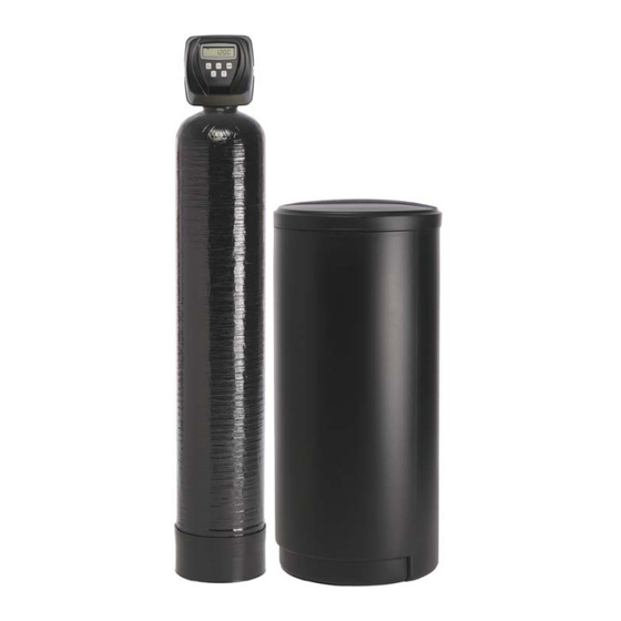
- Page 1 Series 950SM Single Metered Water Softening System Operation and Maintenance Manual...
-
Page 3: Table Of Contents
Table of Contents System Specifications and Warnings ................4 Installation Instructions ....................5 Start-Up Instructions ....................... 11 Series 950 Control Valve Programming ................ 13 Parts Breakdown Front Cover and Drive Assembly ................18 Main Body Internal Parts ..................19 Injector Housing Assembly ..................20 Meter Assembly ....................... -
Page 4: System Specifications And Warnings
System Specifications and Warnings System Specifications Water pressure: 40 psi minimum 100 psi Maximum Water Temperature: 40°F to 110°F Electrical Requirements: Supply Voltage: 120V Supply Frequency: 60Hz Output Voltage: 12V AC Output Current: Maximum 3.0 Amps Water Meter: Pipe Size: 1-1/4” Accuracy: ±... -
Page 5: Installation Instructions
Installation Instructions Installation Instructions... - Page 7 Installation Instructions Pre-Installation Checklist 1. A standard electrical outlet (120V/160Hz) must be located within 12’ of installation site. 2. A functioning floor drain, washer sand pipe or suitable location for waste water discharge must be located within 20’ of installation site. All plumbing should be done in accordance with local plumbing codes.
- Page 8 Installation Instructions 5. Plumbing Preparations: Unscrew the two plastic nuts (#1) and pull on the two brass connectors (#4) to remove them from the bypass assembly. Next remove the white plastic rings (#2) and the O-rings. (#3) See Figure 1 •...
- Page 9 Installation Instructions 7. Locate Polytube Insert: Now that the water softener is connected to the existing plumbing, the drain line may be connected. First, locate and remove the polytube insert (#2) from the gray cable on the left side of the control valve. 8.
- Page 10 Installation Instructions 11. Connecting the overflow line: The brine overflow fitting is located on the outside of the salt container approximately 12” down from the top. Connect 1/2” drain tubing to the overflow fitting and run it to the nearest floor drain. This line is a gravity flow line and cannot be run overhead or cannot connect to a drain that is higher than the overflow fitting.
-
Page 11: Start-Up Instructions
Start-Up Instructions Start-Up Figure 1 To begin, place the bypass in the position shown in Figure 1. Place the softener in the Backwash cycle. • To place the softener in the Backwash cycle press and hold the REGEN button (approx. 6 seconds) until the control valve initiates a regeneration cycle. -
Page 13: Series 950 Control Valve Programming
Control Valve Programming Series 950 Control Valve Programming... - Page 14 Control Valve Programming Programming The control valve has been pre-programmed from the factory with the correct regeneration cycle program and cycle times. The gallon capacity between regeneration can be changed by adjusting the water hardness. Step 1 - Press the NEXT and the UP Arrow buttons at the same time and hold for 2 seconds. Step 2 - Raw Water Hardness: Adjust to the correct hardness by pressing the UP or DOWN arrow button.
- Page 15 Control Valve Programming Set the Time of Day The time of day should only need to be set after initial installation or after an extended power outage. If an extended power outage has occurred, the time of day will flash indicating that it needs to be set. Step 1 - Press SET CLOCK Step 2 - Current Time of Day - Hours: Adjust to the correct hour by pressing the UP or DOWN arrow button.
-
Page 17: Parts Breakdown
Parts Breakdown Parts Breakdown... -
Page 18: Front Cover And Drive Assembly
Parts Breakdown Front Cover and Drive Assembly Drawing Part No. Description Quantity V3175CC-01 Front Cover Assembly V3107-01 Drive Motor V3106-01 Drive Bracket and Spring Clip V3108CC Circuit Board V3110 Drive Reducing Gear V3109 Drive Gear Cover Not Shown V3186 Transformer 110VAC-12VAC When replacing the battery, align positives and push down to fully seat. -
Page 19: Main Body Internal Parts
Parts Breakdown Main Body Internal Parts... -
Page 20: Injector Housing Assembly
Parts Breakdown Injector Housing Assembly Drawing Part No. Description Quantity V3176 Injector Cap V3152 O-Ring Injector Cap V3177-01 Injector Screen V3010-1A Injector Assembly – A Black V3010-1B Injector Assembly – B Brown V3010-1C Injector Assembly – C Violet V3010-1D Injector Assembly – D Red V3010-1E Injector Assembly –... -
Page 21: Meter Assembly
Parts Breakdown Meter Assembly Breakdown... -
Page 22: Brine Elbow Refill Flow Assembly And Refill Port Plug
Parts Breakdown Brine Elbow Refill Flow Assembly and Refill Port Plug Drawing Part No. Description Quantity V3195-01 Refill Port Plug Assembly normally used H4615 Brine Elbow Locking Clip H4628 Elbow 3/8” Liquifit V3163 Brine Elbow O-Ring V3165-01 Flow Control Retainer Assembly .50 gpm V3182 Brine Refill Flow Control Button .50 gpm V4144-01... -
Page 23: Drain Line Assembly
Parts Breakdown Drain Line Assembly Drawing Part No. Description Quantity H4615 Drain Elbow Locking Clip PKP10TS8- Polytube Insert 5/8” BULK V3192 Drain Elbow Nut V3158-01 Drain Elbow !” Male NPT V3163 Drain Elbow O-Ring V3159-01 Drain Flow Control Retainer Assembly Drain Line Flow Control Button* V3162-XX *The size of your system will determine which... -
Page 24: 1" Drain Assembly
Parts Breakdown 1” Drain Assembly... -
Page 25: Bypass Breakdown
Parts Breakdown Bypass Assembly Breakdown... -
Page 26: Bypass Valve Operation
Parts Breakdown Bypass Valve Operation... -
Page 27: Installation Fitting Assemblies
Parts Breakdown Installation Fitting Assemblies... - Page 28 Parts Breakdown Installation Fitting Assemblies...
-
Page 29: Brine Tank Assembly
Parts Breakdown Brine Tank Assembly... -
Page 30: System Specifications
System Specifications Mineral Tank Specifications Grain Mineral Gravel Resin Distributor Capacity Tank Lbs. Cu/Ft Assembly 32,000 8x44 No Gravel D931-44 48,000 10x47 No Gravel D931-54 60,000 12x52 No Gravel D931-54 70,000 12x52 No Gravel 2.33 D931-54 80,000 13x54 No Gravel 2.66 D931-54 90,000... - Page 31 System Specifications Control Valve Specifications Drain Line Brine Line Brine Refill Grain Injector Flow Control Flow Control Time Capacity Size Min. 32,000 D (RED) 6 MIN 11 SEC 48,000 E (WHITE) 7 MIN 52 SEC 60,000 E (WHITE) 13 MIN 20 SEC 70,000 E (WHITE) 15 MIN 20 SEC...
-
Page 32: Service Instructions
Service Instructions Service Instructions... - Page 33 Service Instructions Service Instructions Drive Assembly - Disassembly and Inspection: Remove the valve cover to access the drive assembly. The drive bracket must be removed to access the drive cap assembly and pistons or the drive gear cover. It is not necessary to remove the circuit board from the drive bracket to remove the drive bracket.
- Page 34 Service Instructions Drive Assembly - Reassembly: If the drive gear cover was removed, reinstall it with the large clip orientated towards the bottom. If all three clips are outside of the gear shroud on the drive bracket the drive gear cover slips easily into place.
- Page 35 Service Instructions The drive cap assembly contains the drive cap, the main drive gear, drive cap spline, piston rod and various other parts that should not be dissembled in the field. Visually inspect the drive cap for damage and free operation of the gear and threaded rod. The only replaceable part on the drive cap assembly is the O-ring.
- Page 36 Service Instructions Injector Cap, Screen, and Injector - Disassembly and Inspection Unscrew the injector cap and lift off. Loosen the cap with special plastic wrench (part number) or pliers if necessary. Attached to the injector cap is a screen. Remove the screen and clean if fouled.
-
Page 37: Troubleshooting For The Control Valve
Troubleshooting the Control Valve Troubleshooting Control Valve... - Page 38 Water Softener Log Sheet It is important to keep a log of the water softener programming and other important information. This is necessary for repairs and other troubleshooting needs. Volume Date Time Hardness Salt Usage Pressure Remaining...
- Page 39 Control Valve Trouble Shooting Problem Possible Cause Solution No power at electrical outlet Repair outlet or use working outlet Control Valve Power Cord not plugged Make sure Control Valve Power Cord is onto Control Valve Circuit Board connected securely at both ends No display on Control Valve Circuit Board Verify proper voltage is being delivered to...
- Page 40 Control Valve Trouble Shooting Problem Possible Cause Solution Fully close Bypass Valve or replace. Also Bypass Valve is open or faulty check for multiple bypasses Media is exhausted due to high water Check program settings or diagnostics for usage abnormal water usage Remove Meter and check for rotation or Meter not registering foreign material...
- Page 41 Control Valve Trouble Shooting Problem Possible Cause Solution Injector is plugged Remove Injector and clean or replace Faulty Brine Piston Replace Brine Piston Brine line tubing connection leak Inspect Tubing and Fittings for air leak Drain line restriction or debris can cause Inspect drain line and clean to correct Control Valve fails to draw excess back pressure on Injector...
- Page 42 Control Valve Trouble Shooting Problem Possible Cause Solution Check motor connections then Press NEXT and REGEN buttons at the same Motor failure during a regeneration time for 3 seconds to resynchronize software with piston. Replace Piston and Seal and Spacer Err - 1003 = Control valve Foreign matter built up on Piston and Seal Stack Assemblies.
- Page 43 Notes...
- Page 44 OM-A950SM Printed in the USA Version 161026.1...
Need help?
Do you have a question about the 950SM Series and is the answer not in the manual?
Questions and answers
How do I reset the regeneration cycle to a different time?
To reset the regeneration cycle on a SENTRY II 950SM Series, press and hold the REGEN button for approximately 6 seconds until the unit begins a regeneration cycle.
This answer is automatically generated
We added salt and the capacity remaining number is still going down. What else do we do?
Check for leaking fixtures that may be exhausting capacity or determine if the system is undersized. Also, verify the program settings to ensure they match the water quality and application needs.
This answer is automatically generated