
Subscribe to Our Youtube Channel
Related Manuals for SENTRY II 930TA Series


Summary of Contents for SENTRY II 930TA Series
- Page 1 Series 930TA Twin Meter Alternating Water Softening System Operation and Maintenance Manual...
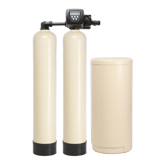
- Page 3 Product Overview Controller Display Connecting Pipes Alternator Second Tank Adapter Unit B Unit A...
-
Page 5: Table Of Contents
Table of Contents System Specifications and Warnings ................6 Introduction ........................7 Installation Instructions ....................11 Start-Up Instructions ....................... 15 Manually Regenerating the Water Softener ..............16 Series 930 Control Valve Programming ................ 17 Parts Breakdown Front Cover and Drive Assembly ................22 Drive Cap Assembly, Seal and Spacer Stack and Pistons!!!!!!!!.!!23 Main Internal Body Parts .................. -
Page 6: System Specifications And Warnings
System Specifications and Warnings System Specifications Water pressure: 40 psi minimum 100 psi Maximum Water Temperature: 40°F to 110°F Electrical Requirements: Supply Voltage: 120V Supply Frequency: 60Hz Output Voltage: 12V AC Output Current: Maximum 3.0 Amps Water Meter: Pipe Size: 1” Accuracy: ±... -
Page 7: Introduction
Introduction INTRODUCTION Long term, successful operation of any water softening system depends upon the care and attention it receives. Ordinarily, water treatment systems will provide uniform performance after the initial start-up period and operation is stable. Gallonage delivery between regenerations and treated water purity usually do not vary appreciably over the life of the resins--as long as the mineral content of the incoming water does not change. - Page 8 Introduction The Softening Process - When Ca++ or Mg++ ions have occupied most of the reaction points, hardness will begin to slip through the bed in increasing amounts. This rise in hardness in the effluent is an indication that the effective capacity of the CATION EXCHANGER has been reached.
- Page 9 Introduction NORMAL OPERATOR RESPONSIBILITIES Long term, reliable system performance depends upon how conscientiously the equipment is operated and maintained. Operator responsibilities to assure operation should include the following recommended practices: MAINTAIN OPERATING LOGS Operators should maintain close control of the process by monitoring system performance daily.
- Page 10 Introduction BRINE AND SLOW RINSE Raw water is directed through the injector built into the main regeneration control. A venturi action in the injector draws the required amount of brine into the softener. The solution of salt water then passes down-flow through the resin bed, through the lower hub and lateral distribution system, up the distributor pipe and exits through the drain port of the control valve and out to drain.
-
Page 11: Installation Instructions
Installation Instructions Pre-Installation Checklist 1. A standard electrical outlet (120V/160Hz) must be located within 12’ of installation site. 2. A functioning floor drain, washer stand pipe or suitable location for waste water discharge must be located within 20’ of installation site. All plumbing should be done in accordance with local plumbing codes. - Page 12 Installation Instructions 5. Plumbing Preparations: Unscrew the two plastic nuts (#1) and pull on the two brass connectors (#4) to remove them from the bypass assembly. Next remove the white plastic rings (#2) and the O-rings. (#3) See Figure 1 •...
- Page 13 Installation Instructions 7. Locate Polytube Insert: Now that the water softener is connected to the existing plumbing, the drain line may be connected. First, locate and remove the polytube insert (#2) from the gray cable on the left side of the control valve. 8.
- Page 14 Installation Instructions 11. Connecting the overflow line: The brine overflow fitting is located on the outside of the salt container approximately 12” down from the top. Connect 1/2” drain tubing to the overflow fitting and run it to the nearest floor drain. This line is a gravity flow line and cannot be run overhead or cannot connect to a drain that is higher than the overflow fitting.
-
Page 15: Start-Up Instructions
Start-Up Instructions Start-Up Figure 1 To begin, place the bypass in the position shown in Figure 1. Place the softener in the Backwash cycle. • To place Unit A in the Backwash cycle press and hold the REGEN button (approx. 6 seconds) until the control valve initiates a regeneration cycle. -
Page 16: Manually Regenerating The Water Softener
Manually Regenerating the Water Softener Reasons you may want to manually regenerate the water softener: 1. If the brine tank has run out of salt it will be necessary to regenerate the online and offline tanks. (Unit A and Unit B) •... -
Page 17: Series 930 Control Valve Programming
Control Valve Programming Series 930 Control Valve Programming... - Page 19 Control Valve Programming Programming The control valve has been pre-programmed from the factory with the correct regeneration cycle program and cycle times. The gallon capacity between regeneration can be changed by adjusting the water hardness. Step 1 - Press the NEXT and the UP Arrow buttons at the same time and hold for 2 seconds. Step 2 - Raw Water Hardness: Adjust to the correct hardness by pressing the UP or DOWN arrow button.
- Page 20 Control Valve Programming Set the Time of Day The time of day should only need to be set after initial installation or after an extended power outage. If an extended power outage has occurred, the time of day will flash indicating that it needs to be set. Step 1 - Press SET CLOCK Step 2 - Current Time of Day - Hours: Adjust to the correct hour by pressing the UP or DOWN arrow button.
-
Page 21: Parts Breakdown
Parts Breakdown Parts Breakdown... -
Page 22: Front Cover And Drive Assembly
Parts Breakdown Front Cover and Drive Assembly Drawing Part No. Description Quantity V3175CC-01 Front Cover Assembly V3107-01 Drive Motor V3106-01 Drive Bracket and Spring Clip V3108CC Circuit Board V3110 Drive Reducing Gear V3109 Drive Gear Cover Not Shown V3186 Transformer 110VAC-12VAC When replacing the battery, align positives and push down to fully seat. -
Page 23: Drive Cap Assembly, Seal And Spacer Stack And Pistons!!!!!!!!.!!23
Parts Breakdown Drive Cap Assembly, Seal and Spacer Stack and Pistons Drawing Part No. Description Quantity V3005 Seal and Spacer Stack Assembly V3004 Drive Cap Assembly V3135 Drive Cap Assembly O-Ring V3174 Brine Piston V3011 Main Downflow Piston Assembly... -
Page 24: Main Internal Body Parts
Parts Breakdown Main Body Internal Parts... - Page 25 Parts Breakdown Drawing Part No. Description Quantity V3470 Transfer Drive Cap Screw V3724 Transfer Drive Cap Washer V4005-01 Transfer Drive Cap V4029 Transfer Drive Cap O-Ring V4015 Transfer Spring V4014 Transfer Spring Support V4036 Rotor Disc Assembly V3105 Distributor O-Ring V3180 Tank O-Ring V4016...
-
Page 26: Injector Housing Assembly
Parts Breakdown Injector Housing Assembly Drawing Part No. Description Quantity V3176 Injector Cap V3152 O-Ring Injector Cap V3177-01 Injector Screen V3010-1A Injector Assembly – A Black V3010-1B Injector Assembly – B Brown V3010-1C Injector Assembly – C Violet V3010-1D Injector Assembly – D Red V3010-1E Injector Assembly –... -
Page 27: Meter Assembly Breakdown
Parts Breakdown Meter Assembly Breakdown... -
Page 28: Brine Elbow Refill Flow Assembly And Refill Port Plug
Parts Breakdown Parts Breakdown Brine Elbow Refill Flow Assembly and Refill Port Plug Drawing Part No. Description Quantity V3195-01 Refill Port Plug Assembly normally used H4615 Brine Elbow Locking Clip JCP-P-6 Polytube Insert 3/8” JCPG-6PBLK Brine Elbow Nut 3/8” V3330-01 Brine Elbow with Flow Control Retainer Assembly V3163 Brine Elbow O-Ring... -
Page 29: Drain Line Assembly
Parts Breakdown Drain Line Assembly Drawing Part No. Description Quantity H4615 Drain Elbow Locking Clip PKP10TS8-BULK Polytube Insert 5/8” V3192 Drain Elbow Nut V3158-01 Drain Elbow "” Male NPT V3163 Drain Elbow O-Ring V3159-01 Drain Flow Control Retainer Assembly Drain Line Flow Control Button* V3162-XX *The size of your system will determine which flow control button is needed. -
Page 30: Connecting Pipes And Second Tank Adapter
Parts Breakdown Connecting Pipes and Second Tank Adapter... -
Page 31: Bypass Assembly Breakdown
Parts Breakdown Bypass Assembly Breakdown... -
Page 32: Bypass Valve Operation
Parts Breakdown Bypass Valve Operation... -
Page 33: Installation Fitting Assemblies
Parts Breakdown Installation Fitting Assemblies... - Page 34 Parts Breakdown Installation Fitting Assemblies...
-
Page 35: Brine Tank Assembly
Parts Breakdown Brine Tank Assembly... -
Page 36: System Specifications
System Specifications Mineral Tank Specifications Grain Mineral Gravel Resin Distributor Capacity Tank Lbs. Cu/Ft Assembly 32,000 8x44 No Gravel D931-44 48,000 10x47 No Gravel D931-54 60,000 12x52 No Gravel D931-54 70,000 12x52 No Gravel 2.33 D931-54 80,000 13x54 No Gravel 2.66 D931-54 90,000... - Page 37 System Specifications Brine Tank Specifications Grain Brine Deck Brine Float Brine Capacity Tank Height (in.) Valve Well 32,000 18 x 33 HBVA474-6 HBW-30S 48,000 18 x 40 HBVA474-6 HBW-36S 60,000 18 x 40 HBVA474-6 HBW-36S 70,000 18 x 40 HBVA474-6 HBW-36S 80,000 18 x 40...
-
Page 38: Service Instructions
Service Instructions Service Instructions Drive Assembly - Disassembly and Inspection: Remove the valve cover to access the drive assembly. The drive bracket must be removed to access the drive cap assembly and pistons or the drive gear cover. It is not necessary to remove the circuit board from the drive bracket to remove the drive bracket. - Page 39 Service Instructions Drive Assembly - Reassembly: If the drive gear cover was removed, reinstall it with the large clip orientated towards the bottom. If all three clips are outside of the gear shroud on the drive bracket the drive gear cover slips easily into place.
- Page 40 Service Instructions Main Piston and Brine Piston - Reassembly Reattach the main piston to the drive cap assembly. Reattach the brine piston to the main piston. Reinsert the drive cap assembly and piston into the seal and spacer stack assembly insert the four screws and tighten the drive cap assembly.
- Page 41 Service Instructions Injector Cap, Screen, Injector Plug and Injector - Reassembly Press injector into its borehole and press until seated all the way down. Replace the injector cap. Refill Flow Control Assembly - Disassembly and Inspection To clean or replace the refill flow control, remove the nut and then pull the fitting straight out.
-
Page 42: Servicing The Transfer Cap Assembly
Servicing the Transfer Cap Assemblies To Service the Transfer Cap Assembly: The control valve’s back plate must be removed first to allow access to removing the transfer cap assembly. Note: Hold slight downward pressure on the top left corner of the back plate while using a thin flat screwdriver or knife blade to push in on the locking tabs, this will release the back plate and it will twist to the left off of the valve body. - Page 43 Servicing the Transfer Cap Assemblies To remove seals gently pull out on the outer lip of the seal to lift the seal out from its cavity being careful not to damage the face surface of the seal. To reassemble re-seat the seals into the seal cavity of the control valve body being sure that the lip of the seal is facing outward.
- Page 44 Servicing the Transfer Cap Assemblies Noting the one possible orientation of the transfer drive cap, use one hand to press in and support the transfer drive cap while using the opposing had to start two screws in, one on the top and one opposing on the bottom. Tighten the screws in evenly so that the cap seats the O-ring without getting pinched or damaged.
-
Page 45: Water Softener Log Sheet
Water Softener Log Sheet It is important to keep a log of the water softener programming and other important information. This is necessary for repairs and other troubleshooting needs. Volume Online Status Date/Time Hardness Salt Usage Pressure Remaining... -
Page 46: Troubleshooting The Control Valve
Control Valve Trouble Shooting Problem Possible Cause Solution No power at electrical outlet Repair outlet or use working outlet Control Valve Power Cord not plugged Make sure Control Valve Power Cord is onto Control Valve Circuit Board connected securely at both ends No display on Control Valve Circuit Board Verify proper voltage is being delivered to... - Page 47 Control Valve Trouble Shooting Problem Possible Cause Solution Fully close Bypass Valve or replace. Also Bypass Valve is open or faulty check for multiple bypasses Media is exhausted due to high water Check program settings or diagnostics for usage abnormal water usage Remove Meter and check for rotation or Meter not registering foreign material...
- Page 48 Control Valve Trouble Shooting Problem Possible Cause Solution Injector is plugged Remove Injector and clean or replace Faulty Brine Piston Replace Brine Piston Brine line tubing connection leak Inspect Tubing and Fittings for air leak Drain line restriction or debris can cause Inspect drain line and clean to correct Control Valve fails to draw excess back pressure on Injector...
- Page 49 Control Valve Trouble Shooting Problem Possible Cause Solution Check motor connections then Press NEXT and REGEN buttons at the same Motor failure during a regeneration time for 3 seconds to resynchronize software with piston. Replace Piston and Seal and Spacer Err - 1003 = Control valve Foreign matter built up on Piston and Seal Stack Assemblies.
-
Page 50: Manufacturers Warranty
Manufacturers Warranty Manufacturer’s Limited Warranty Pacific Water Inc. (“Manufacturer”) warrants to the original owner that its Water Conditioning Equipment will be free from defects in material and workmanship under normal use and service for a period of five (5) years from the date of installation, when installed and operated within recommended parameters. No warranty is made with respect to defects not reported to Manufacturer within the warranty period and/or defects or damages due to neglect, misuse, alterations, accident, misapplication, physical damage, or damage caused by fire, floods, acts of God, freezing or hot water or similar causes. - Page 52 OM-A930TA Printed in the USA Version 14/05/29.1...
Need help?
Do you have a question about the 930TA Series and is the answer not in the manual?
Questions and answers