
Related Manuals for Elettrotest TPS/M 1500


Summary of Contents for Elettrotest TPS/M 1500
- Page 1 TPS/M 1500-9000VA USER MANUAL Clicca qui per vedere il manuale in versione Italiana. 01/02/22 62000440_08_User Manual TPS/M 1500-9000VA...
- Page 2 TPS/M 6000 99111503 TPS/M 9000 99111653 This manual is written from TPS/M firmware version TPSX 09_. Please check the latest manual version at www.elettrotestspa.it To consult older manual versions, please contact our support at service@elettrotestspa.it 01/02/22 62000440_08_User Manual TPS/M 1500-9000VA...
- Page 3 Brochure Brochure for all the TPS-HPS-CPS models Describes all the machine modifiable TPS Parameters parameters and the start-up sequence. Parameters TPS protocol Describes how the Elettrotest remote Elettrotest Elettrotest communication protocol works. Protocol Describes how the SCPI remote TPS protocol...
- Page 4 Documents Description Link QR-code PS Interface Software for remote use. PS_interface Manual and LabView Drivers for PS- Driver Driver LabView interface LabView 01/02/22 62000440_08_User Manual TPS/M 1500-9000VA...
- Page 5 TPS/M/M is an high performance variable voltage generator (amplitude and frequency) in order to simulate and electrical line for test for different application (laboratory, test line, production line) Responsability: Elettrotest disclaims any responsibility for damage to people or things caused by an improper use of its products. Mandatory Verify voltage, power and frequency compatibility between TPS/M range and electrical specification of equipment under test (EUT).
- Page 6 • Keep the ventilation holes on the front and rear free from obstruction. • Do not make dielectric strengths test on the input or output of the equipment. Contact Elettrotest if you need to do specific test ELECTRIC RISK There are dangerous voltages inside TPS/M and over the output connector.
- Page 7 • the symbol (crossed-out wheeled bin) shown on the product or on the packaging and on the instruction sheet indicates that the equipment must be disposed of separately; • in the event of illegal disposal of electrical and electronic waste, the penalties are specified by local waste disposal legislation. 01/02/22 62000440_08_User Manual TPS/M 1500-9000VA...
-
Page 8: Table Of Contents
1.3. TECHNICAL SPECIFICATIONS ....................13 1.3.1. Limitation current ......................13 1.4. MECHANICAL DRAWINGS ....................14 1.4.1. TPS/M 1500 | TPS/M 3000..................14 1.4.2. TPS/M 6000 ........................15 1.4.3. TPS/M 9000 ........................16 NOTES FOR USERS ........................17 2.1. Switching ON ........................17 2.2. - Page 9 5.3.1. Overvoltage/Undervoltage alarms ................38 5.3.2. Overtemperature alarms ..................... 38 5.3.3. Inverter alarm ......................39 5.3.4. Max DV OUT alarm ....................... 39 5.3.5. Limit IOUT alarm ......................39 GUARANTEE ..........................40 REVISION INDEX ......................... 40 01/02/22 62000440_08_User Manual TPS/M 1500-9000VA...
-
Page 10: Introduction
TPS/M also allows to synchronize the output frequency with the frequency of the supply line; this synchronization is obtained both in frequency and in phase with the line. This allows a completely synchronous output with regard to the supply line. 01/02/22 62000440_08_User Manual TPS/M 1500-9000VA... -
Page 11: User Interface
It is monitored both the set voltage and the set frequency and the output voltage is read with a precision of 0.3%. The user is also warned in case of overcurrent obtainable by the TPS/M, or in case of high loss in the wires, that should not exceed 5% of the set voltage. 01/02/22 62000440_08_User Manual TPS/M 1500-9000VA... -
Page 12: Models
99101133 99101133 DC options 99101120 99101120 99101120 99101120 Only on 300V range With Resistive load Rack and Desk solution You can set up 320Hz by serial command, but with derating of performance and maximum voltage 01/02/22 62000440_08_User Manual TPS/M 1500-9000VA... -
Page 13: Technical Specifications
1.3. TECHNICAL SPECIFICATIONS 1.3.1. Limitation current 2.50 2.00 1.50 1.00 0.50 0.00 10.0 20.0 30.0 40.0 50.0 60.0 Time (sec) 01/02/22 62000440_08_User Manual TPS/M 1500-9000VA... -
Page 14: Mechanical Drawings
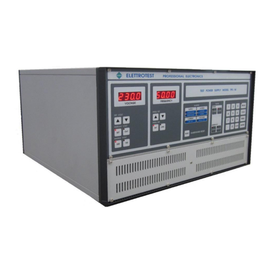
1.4. MECHANICAL DRAWINGS 1.4.1. TPS/M 1500 | TPS/M 3000 ELETTROTEST PROFESSIONAL ELECTRONICS ELETTROTEST VOLTAGE FREQUENCY ALARMS MODE SET VOLT FREQ. SET SENSE SUPPLY SYSTEM PROG OVERVOLTAGE OVER TEMP UNDERVOLTAGE INVERTER VOLT DISPLAY VOLT FREQ. REF OUTPUT CURRENT VOLTAGE LIMIT OUT 1... -
Page 15: Tps/M 6000
OUT 1 OUT 1 OUT 2 OUT 3 LINE LIMIT OUT 2 OUT 2 FREQ. LIMIT OUT 3 OUT 3 RANGE VOLT INTERFACE ENTER RESET HARDWARE RESET CLEAR MAIN SUPPLY RS232 FUSES SENSE 01/02/22 62000440_08_User Manual TPS/M 1500-9000VA... -
Page 16: Tps/M 9000
OUT 1 OUT 1 OUT 2 OUT 3 LINE LIMIT OUT 2 OUT 2 FREQ. LIMIT OUT 3 OUT 3 RANGE VOLT INTERFACE HARDWARE RESET ENTER RESET CLEAR MAIN SUPPLY RS232 EARTH SENSE FUSES 01/02/22 62000440_08_User Manual TPS/M 1500-9000VA... -
Page 17: Notes For Users
TPS_Parameters manual. 2.3. VOLTAGE MENU 2.3.1. Setting Voltage There are two ways to set the Voltage: through the appropriate buttons UP and DOWN placed on the left on the control panel or through the numeric keyboard. 01/02/22 62000440_08_User Manual TPS/M 1500-9000VA... -
Page 18: Range Setting
ENTER. 2.4. RANGE SETTING The TPS/M range buttons allows to make use of the full output power at different voltages. There are two different ranges: 300 Volt and 150 Volt. 01/02/22 62000440_08_User Manual TPS/M 1500-9000VA... -
Page 19: Voltage Visualization
0.3% at full scale range. If the set voltage is changed, the display returns to show the set value. In case of 4 wires operation, the display shows the voltage on the sense inputs. 01/02/22 62000440_08_User Manual TPS/M 1500-9000VA... -
Page 20: Frequency Menu
50 Hertz takes place, TPS/M is connected to the network frequency and the display concerning the frequency switches off. The state of connections to the network is indicated by the led corresponding to the button LINE. 01/02/22 62000440_08_User Manual TPS/M 1500-9000VA... -
Page 21: Mode Menu
TPS/M doesn’t guarantee that the value of the output voltage is equal to the set-up voltage and an error signal appears (see at voltage alarms). 01/02/22 62000440_08_User Manual TPS/M 1500-9000VA... -
Page 22: Alarms
2.8. ALARMS 01/02/22 62000440_08_User Manual TPS/M 1500-9000VA... -
Page 23: Loading Alarms
If the output voltage is not equal to the set off one a signal of error is visualized by means of the led MAX V at the voice VOLTAGE. This kind of alarm does not cause any block to TPS/M. 01/02/22 62000440_08_User Manual TPS/M 1500-9000VA... -
Page 24: Installation
Save all packing materials in case the product has to be returned one day. If any damage is found, please file a claim with the carrier immediately. Do not return the product to the factory without obtaining the prior Return Merchandise Authorization (RMA) acceptance from ELETTROTEST S.P.A. 01/02/22 62000440_08_User Manual TPS/M 1500-9000VA... -
Page 25: Power Cabling
FUSE SENSE 1. SENSE output. 2. Power output connector. 3. Eart connector. 4. Power input connector. 5. Fuse GL16A. 6. General switch. 7. Serial 25 poles or 9 poles connector. 8. Fan. 9. Ventilation Grill 01/02/22 62000440_08_User Manual TPS/M 1500-9000VA... -
Page 26: Tps/M 3000
FUSE SENSE 1. SENSE output. 2. Power output connector. 3. Eart connector. 4. Power input connector. 5. Fuse GL25A. 6. General switch. 7. Serial 25 poles or 9 poles connector. 8. Fan. 9. Ventilation Grill 01/02/22 62000440_08_User Manual TPS/M 1500-9000VA... -
Page 27: Tps/M 6000
• Use a cable of suitable section (max 5*6mm • Make sure that the phases are joined with the indicate sequence. • Reclose the cable glands • Reclose the terminal cover joining it on the two lateral hook MAIN SUPPLY RS232 FUSES SENSE 01/02/22 62000440_08_User Manual TPS/M 1500-9000VA... -
Page 28: Tps/M 9000
• Use a cable of suitable section (max 6*6mm • Make sure that the phases are joined with the indicate sequence. • Reclose the cable glands. • Reclose the terminal cover joining it on the two lateral hook 01/02/22 62000440_08_User Manual TPS/M 1500-9000VA... - Page 29 RS232 EARTH SENSE FUSES 1. Sense output tension. 2. Power output connector. 3. Eart connector. 4. Power input connector. 5. Fuse GL25A. 6. General switch. 7. Serial 25 poles or 9 poles connector. 8. Fan. 01/02/22 62000440_08_User Manual TPS/M 1500-9000VA...
-
Page 30: Protection Device
It's recommended to use B type RCD with a earth leakage current of 30 mA according to the nominal input characteristic (see section 1.2). The machine can absorb more than 100mA at high frequency, be secure the RCD has the filter for high frequency. 01/02/22 62000440_08_User Manual TPS/M 1500-9000VA... -
Page 31: Magneto-Thermal Protection
Current Type Voltage F1, F2, F3 Mainline Input 10x38 500V Input Aux supply 10x38 400V Aux Supply 5x20 3.15A 250V Safety Circuit 5x20 1.25A 250V The layout may be different and depends the model design 01/02/22 62000440_08_User Manual TPS/M 1500-9000VA... -
Page 32: Internal Fuses Tps/M 9000
Input cable USB KEY 3.3.10. ACCESSORY TPS/M 3000 Item Description FUSE 10x38 25A GL 500V FUSE 5x20 3.15A AT 250V FUSE 5x20 1.25A AT 250V MULTICONTACT KT425-SL RED MULTICONTACT KT425-SL BLACK MULTICONTACT LS425-SL USB KEY 01/02/22 62000440_08_User Manual TPS/M 1500-9000VA... -
Page 33: Accessory Tps/M 6000
3.3.12. ACCESSORY TPS/M 9000 Item Description FUSE 10x38 25A GL 500V FUSE 5x20 3.15A AT 250V FUSE 5x20 1.25A AT 250V MULTICONTACT KT425-SL RED MULTICONTACT KT425-SL BLACK MULTICONTACT LS425-SL MULTICONTACT KBT6-AR-N/10-S RED MULTICONTACT KBT6-AR-N/10-S BLACK USB KEY 01/02/22 62000440_08_User Manual TPS/M 1500-9000VA... -
Page 34: Wiring Diagram
3.4. WIRING DIAGRAM 3.4.1. 2 WIRE CONFIGURATION 01/02/22 62000440_08_User Manual TPS/M 1500-9000VA... -
Page 35: Wire Configuration
3.4.2. 4 WIRE CONFIGURATION 01/02/22 62000440_08_User Manual TPS/M 1500-9000VA... -
Page 36: Remote Control
Hereunder is shown the table of existence for the protocols and the hardware: MODELS Communication ports Protocols RS232 RS485 Elettrotest Elettrotest SCPI Modbus CPS/M CPS/T TPS/M TPS/T TPS/M/D XPS/M XPS/T X : Enabled (X) : Option 01/02/22 62000440_08_User Manual TPS/M 1500-9000VA... -
Page 37: Service And Maintenance
• From 7 to 10 Years for general maintenance; You can check the TPS/M working hours on the display and via remote. Please, note that it is necessary to return the machine to ELETTROTEST S.P.A for the scheduled maintenance. 5.2. -
Page 38: Basic Troubleshooting
*) Check your TPS/M plate to see the designed INPUT voltage for your device. 5.3.2. Overtemperature alarms Cause Solution Check that all the ventilation parts need to be not Fans coverage cover and air filters must be clean Fans Failure Check that all the fans are working correctly 01/02/22 62000440_08_User Manual TPS/M 1500-9000VA... -
Page 39: Inverter Alarm
Check the output voltage and current. The machine is out of calibration. Please contact the Calibration service. 5.3.5. Limit IOUT alarm Cause Solution Chek the output voltage and current, remove the EUT Overload and check the behavior. 01/02/22 62000440_08_User Manual TPS/M 1500-9000VA... -
Page 40: Guarantee
Such document must accompany the apparatus in case of periodic verification always. 7. REVISION INDEX Elettrotest Spa is committed to a program of continuous improvement of products and information to the customer. Therefore, the company reserves the right to make changes to the documentation and specifications without notice and assumes no responsibility for any incorrect information. - Page 41 TPS/M 1500-9000VA MANUALE UTENTE Click here to see the English version. 01/02/22 62000440_08_User Manual TPS/M 1500-9000VA...
- Page 42 99111503 TPS/M 9000 99111653 Questo manuale è scritto per le versioni firmware dalla TPSX 09_. Controlla sempre l’ultima versione del manuale al sito www.elettrotestspa.it Per consultare manuali di versioni precedenti, contatta il supporto Elettrotest: service@elettrotestspa.it 01/02/22 62000440_08_User Manual TPS/M 1500-9000VA...
- Page 43 Parameters TPS protocol Descrive come funziona il protocollo di Elettrotest Elettrotest comunicazione remota Elettrotest. Protocol Descrive come funziona il protocollo di TPS protocol SCPI comunicazione remota SCPI con il tuo SCPI Protocol TPS/M. 01/02/22 62000440_08_User Manual TPS/M 1500-9000VA...
- Page 44 Documents Description Link QR-code Programma per l’utilizzo della macchina in PS Interface PS_interface remoto Manuale e Driver LabView per PS- Driver Driver LabView interface LabView 01/02/22 62000440_08_User Manual TPS/M 1500-9000VA...
- Page 45 (laboratorio, linea di test, linea di produzione). Responsabilità: Elettrotest declina ogni responsabilità per danni a persone o cose causati da un uso improprio dei propri prodotti. Obbligatorio: - Verificare la compatibilità di tensione, potenza e frequenza tra la gamma TPS/M e le specifiche elettriche delle apparecchiature in prova (EUT).
- Page 46 RISCHIO ELETTRICO All’interno del TPS/M e sul connettore di uscita sono presenti tensioni pericolose. Il non rispetto delle avvertenze riportate in questo manuale può portare a shock elettrici anche mortali. 01/02/22 62000440_08_User Manual TPS/M 1500-9000VA...
- Page 47 • In caso di smaltimento abusivo dei rifiuti elettrici ed elettronici sono previste sanzioni stabilite dalle vigenti normative locali in materia di smaltimento. 01/02/22 62000440_08_User Manual TPS/M 1500-9000VA...
- Page 48 2.1. SPECIFICHE TECNICHE ......................13 2.1.1 Corrente di limitazione ....................13 2.2. DISEGNI MECCANICI ......................14 2.2.1 TPS/M 1500 | TPS/M 3000..................14 2.2.2 TPS/M 6000 ........................15 2.2.3 TPS/M 9000 ........................16 NOTE UTENTE ..........................17 3.1. ACCENSIONE ........................17 3.2.
- Page 49 6.3.1 Allarmi di sovratensione ....................42 6.3.2 Allarmi di sovratemperatura ..................42 6.3.3 Allarme inverter ......................42 6.3.4 Allarme Max DV OUT ....................43 6.3.5 Allarme Limit IOUT ....................... 43 GARANZIA........................... 44 REVISIONE ..........................44 01/02/22 62000440_08_User Manual TPS/M 1500-9000VA...
-
Page 50: Introduzione
Ciò consente un'uscita completamente sincrona rispetto alla linea di alimentazione. 1.1.3 Interfaccia utente TPS/M è progettato per avere un'interfaccia user-friendly. È inoltre prevista la possibilità di un controllo da computer host, consentendo così di eseguire i test in automatico. 01/02/22 62000440_08_User Manual TPS/M 1500-9000VA... - Page 51 Viene monitorata sia la tensione impostata che la frequenza impostata e la tensione di uscita viene letta con una precisione dello 0,3%. L'utente viene inoltre avvisato in caso di sovracorrente ottenibile dal TPS/M, o in caso di elevata perdita dei fili, che non deve superare il 5% della tensione impostata. 01/02/22 62000440_08_User Manual TPS/M 1500-9000VA...
-
Page 52: Modelli
DC options 99101120 99101120 99101120 99101120 Solo a range 300V Con carico resistivo Soluzione per banchi o racks È possibile impostare fino a 320Hz tramite comando remoto, ma con declassamento delle prestazioni e tensione massima. 01/02/22 62000440_08_User Manual TPS/M 1500-9000VA... -
Page 53: Specifiche Tecniche
2.1. SPECIFICHE TECNICHE 2.1.1 Corrente di limitazione 2.50 2.00 1.50 1.00 0.50 0.00 10.0 20.0 30.0 40.0 50.0 60.0 Time (sec) 01/02/22 62000440_08_User Manual TPS/M 1500-9000VA... -
Page 54: Disegni Meccanici
2.2. DISEGNI MECCANICI 2.2.1 TPS/M 1500 | TPS/M 3000 ELETTROTEST PROFESSIONAL ELECTRONICS ELETTROTEST VOLTAGE FREQUENCY ALARMS MODE SET VOLT FREQ. SET SENSE SUPPLY SYSTEM PROG OVERVOLTAGE OVER TEMP UNDERVOLTAGE INVERTER VOLT DISPLAY VOLT FREQ. REF CURRENT VOLTAGE OUTPUT LIMIT OUT 1... -
Page 55: Tps/M 6000
OUT 1 OUT 1 OUT 2 OUT 3 LINE LIMIT OUT 2 OUT 2 FREQ. LIMIT OUT 3 OUT 3 RANGE VOLT INTERFACE RESET HARDWARE RESET CLEAR ENTER MAIN SUPPLY RS232 FUSES SENSE 01/02/22 62000440_08_User Manual TPS/M 1500-9000VA... -
Page 56: Tps/M 9000
OUT 1 OUT 1 OUT 2 OUT 3 LINE LIMIT OUT 2 OUT 2 FREQ. LIMIT OUT 3 OUT 3 RANGE VOLT INTERFACE ENTER RESET HARDWARE RESET CLEAR MAIN SUPPLY RS232 EARTH SENSE FUSES 01/02/22 62000440_08_User Manual TPS/M 1500-9000VA... -
Page 57: Note Utente
La modalità di programmazione consente di configurare un profilo di partenza dell'applicazione, diverso da quello di fabbrica. I parametri modificabili e le modalità di accesso alla modalità di programmazione sono illustrati nella guida rapida Configura parametri. 01/02/22 62000440_08_User Manual TPS/M 1500-9000VA... -
Page 58: Menù Tensione
PROGRAM si spegne. In caso di errore è possibile premere il pulsante ANNULLA che provoca l'uscita dalla routine di programmazione. 01/02/22 62000440_08_User Manual TPS/M 1500-9000VA... -
Page 59: Settaggio Range
15 secondi l'uscita si riaccende e il display Volt visualizza la tensione zero (0.0); Da quel momento TPS/M è pronto a ricevere sulla nuova gamma. 01/02/22 62000440_08_User Manual TPS/M 1500-9000VA... -
Page 60: Visualizzazione Tensione
0,3% a fondo scala. Se la tensione impostata viene modificata, il display torna a visualizzare il valore impostato. In caso di funzionamento a 4 fili, il display mostra la tensione sugli ingressi di rilevamento. 01/02/22 62000440_08_User Manual TPS/M 1500-9000VA... -
Page 61: Menù Frequenza
50 Hertz (ciò è indicato dal lampeggio della frequenza visualizzata); quando avvengono i collegamenti con i 50 Hertz, il TPS/M viene connesso alla frequenza di rete e il display relativo alla frequenza si spegne. 01/02/22 62000440_08_User Manual TPS/M 1500-9000VA... - Page 62 Per tornare al riferimento di frequenza interno premere il pulsante INT, dopo circa 10 secondi il display visualizzerà 50.00 e la frequenza di uscita sarà collegata al riferimento interno. 01/02/22 62000440_08_User Manual TPS/M 1500-9000VA...
-
Page 63: Mode Menu
TPS/M non garantisce che il valore della tensione di uscita sia uguale alla tensione di taratura e compare una segnalazione di errore (vedi allarmi di tensione). 01/02/22 62000440_08_User Manual TPS/M 1500-9000VA... -
Page 64: Allarmi
Anche in caso di cattivo funzionamento delle sezioni di sovraccarico (inverter) il TPS/M si ferma e si accende il led INVERTER. 3.8.3 Allarme di corrente Il TPS/M opera un controllo sulla corrente in uscita che permette di sopportare per un tempo indefinito il cortocircuito in uscita. 01/02/22 62000440_08_User Manual TPS/M 1500-9000VA... -
Page 65: Allarme Di Tensione
Se la tensione di uscita non è uguale a quella impostata viene visualizzata una segnalazione di errore tramite il led MAX V alla voce VOLTAGE. Questo tipo di allarme non provoca alcun blocco al TPS/M. 01/02/22 62000440_08_User Manual TPS/M 1500-9000VA... -
Page 66: Installazione
Se si riscontrano danni, si prega di presentare immediatamente un reclamo al corriere. Non restituire il prodotto in fabbrica senza aver ottenuto la preventiva accettazione dell'Autorizzazione al Reso Merce (RMA) da parte di ELETTROTEST S.P.A. 01/02/22... -
Page 67: Cablaggio Macchina
• Richiudere il coprimorsetti fissandolo sui due ganci laterali. • Collegare il carico del cavo con dimensioni adeguate. • Opzionalmente: collegare i cavi di rilevamento Tenere libera l'area inferiore e laterale per la ventilazione MAIN SUPPLY FUSE SENSE 01/02/22 62000440_08_User Manual TPS/M 1500-9000VA... -
Page 68: Tps/M 3000
• Richiudere i pressacavi. • Richiudere il coprimorsetti fissandolo sui due ganci laterali. • Opzionalmente: collegare i cavi SENSE • Tenere libera l'area inferiore e laterale per la ventilazione N EART MAIN SUPPLY FUSE SENSE 01/02/22 62000440_08_User Manual TPS/M 1500-9000VA... - Page 69 1. Uscita SENSE. 2. Connettore di uscita di alimentazione. 3. Connettore di terra. 4. Connettore di alimentazione. 5. Fusibile GL25A. 6. Interruttore generale. 7. Connettore seriale 25 poli o 9 poli. 8. Ventilatore. 9. Griglia di ventilazione 01/02/22 62000440_08_User Manual TPS/M 1500-9000VA...
-
Page 70: Tps/M 6000
• Utilizzare un cavo di sezione adeguata (max 5*6mm • Assicurarsi che le fasi siano unite con la sequenza indicata. • Richiudere i pressacavi. • Richiudere il coprimorsetti unendolo sui due ganci laterali MAIN SUPPLY RS232 FUSES SENSE 01/02/22 62000440_08_User Manual TPS/M 1500-9000VA... -
Page 71: Tps/M 9000
• Richiudere i pressacavi. • Collegare il cavo di carico di dimensioni adeguate e posizionare il nucleo di ferrite sul cavo di carico con 3 giri vicino al TPS/M • Richiudere il coprimorsetti unendolo sui due ganci laterali 01/02/22 62000440_08_User Manual TPS/M 1500-9000VA... - Page 72 1. Connettori SENSE della tensione 2. Connettore di uscita di alimentazione. 3. Connettore a terra. 4. Connettore di ingresso alimentazione. 5. Fusibile GL25A. 6. Interruttore generale. 7. Connettore seriale 25 poli o 9 poli. 8. Ventole 01/02/22 62000440_08_User Manual TPS/M 1500-9000VA...
-
Page 73: Dispositivi Di Protezione
Le protezioni di sicurezza (magnetiche e differenziali) sono obbligatorie secondo la caratteristica nominale del tuo TPS/M. Un'ulteriore protezione adeguata deve essere aggiunta quando i componenti elettrici (cavo, Apparecchiatura in prova – EUT) non possono supportare le prestazioni del TPS/M. 01/02/22 62000440_08_User Manual TPS/M 1500-9000VA... -
Page 74: Protezioni Differenziali
4.3.6 Fusibili interni TPS/M 3000 Nome Descrizione Taglia Corrente Tipo Tensione Ingresso linea 10x38 500V principale Circuito di sicurezza 5x20 1.25A 250V Alimentazione ausiliari 5x20 3.15A 250V Il layout può essere diverso e dipende dal design del modello. 01/02/22 62000440_08_User Manual TPS/M 1500-9000VA... -
Page 75: Fusibili Interni Tps/M 6000
Tensione F1, F2, F3 Ingresso linea 10x38 500V principale Ingresso 10x38 400V alimentazione aux Alimentazione 5x20 3.15A 250V ausiliari Circuito sicurezza 5x20 1.25A 250V Il layout può essere diverso e dipende dal design del modello. 01/02/22 62000440_08_User Manual TPS/M 1500-9000VA... -
Page 76: Accessori
MULTICONTACT LS425-SL Input cable USB KEY 4.4.2 Accessori TPS/M 3000 Descrizione FUSE 10x38 25A GL 500V FUSE 5x20 3.15A AT 250V FUSE 5x20 1.25A AT 250V MULTICONTACT KT425-SL RED MULTICONTACT KT425-SL BLACK MULTICONTACT LS425-SL USB KEY 01/02/22 62000440_08_User Manual TPS/M 1500-9000VA... -
Page 77: Accessori Tps/M 9000
4.4.4 Accessori TPS/M 9000 Descrizione FUSIBILE 10x38 25A GL 500V FUSIBILE 5x20 3.15A AT 250V FUSIBILE 5x20 1.25A AT 250V MULTICONTACT KT425-SL RED MULTICONTACT KT425-SL BLACK MULTICONTACT LS425-SL MULTICONTACT KBT6-AR-N/10-S RED MULTICONTACT KBT6-AR-N/10-S BLACK USB KEY 01/02/22 62000440_08_User Manual TPS/M 1500-9000VA... -
Page 78: Schema Cablaggio
4.5. SCHEMA CABLAGGIO 4.5.1 Configurazione 2-WIRE 01/02/22 62000440_08_User Manual TPS/M 1500-9000VA... -
Page 79: Configurazione 4-Wire
4.5.2 Configurazione 4-WIRE 01/02/22 62000440_08_User Manual TPS/M 1500-9000VA... -
Page 80: Controllo Remoto
La tabella di esistenza tra hardware, porte di comuncazione e protocolli utilizzabili è mostrata qui sotto. Modelli Porte di Comunicazione Protocolli RS232 RS485 Elettrotest Elettrotest SCPI Modbus CPS/M CPS/T TPS/M TPS/T TPS/M/D XPS/M XPS/T X: Abilitato (X): Opzione disponibile 01/02/22 62000440_08_User Manual TPS/M 1500-9000VA... -
Page 81: Manuntenzione E Service
• Da 7 a 10 anni per la manutenzione generale; Le ore di funzionamento del tuo TPS/M/D possono essere controllate via remoto oppure nel display all’accensione della macchina. Si ricorda che è necessario restituire la macchina a ELETTROTEST S.P.A per la manutenzione programmata. 6.2. -
Page 82: Risoluzione Problemi Base
Malfunzionamento ventole Controllare il corretto funzionamento delle ventole 6.3.3 Allarme inverter Cause Solution Guasto del modulo di Il TPS/T deve essere restituito al fornitore. alimentazione Linee di potenza Controlla l’alimentazione e tutti I fusibili. 01/02/22 62000440_08_User Manual TPS/M 1500-9000VA... -
Page 83: Allarme Max Dv Out
Controllare la tensione e la corrente di uscita. La macchina è fuori calibrazione. Si prega di Calibrazione contattare il service ELETTROTEST. 6.3.5 Allarme Limit IOUT Cause Solution Controllare la tensione e la corrente di uscita, Sovraccarico rimuovere l'EUT e verificarne il comportamento. 01/02/22 62000440_08_User Manual TPS/M 1500-9000VA... -
Page 84: Garanzia
REVISIONE Elettrotest Spa è impegnata in un programma di miglioramento continuo di prodotti e informazioni per il cliente. Pertanto, la società si riserva il diritto di apportare modifiche alla documentazione e alle specifiche senza preavviso e non si assume alcuna responsabilità...
Need help?
Do you have a question about the TPS/M 1500 and is the answer not in the manual?
Questions and answers