Advertisement
Advertisement

Subscribe to Our Youtube Channel
Related Manuals for Cessna Cardinal RG


Summary of Contents for Cessna Cardinal RG
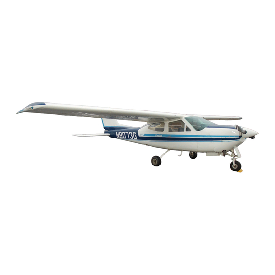
- Page 1 Serial Number 177RG0073 Speed in Knots...
- Page 2 PROPELLER: Constant Speed (Diameter) ....78 inches ENGINE: Lycoming Fuel Injection Engine ..........IO-360-A1B6 200 rated HP at 2700 RPM ------------------------------------------------------------------------------------------------------------------------------------------------ * This manual covers operation of the Cardinal RG which is certificated as Model 177RG under FAA Type Certificate No. A20CE.
- Page 3 Service Manuals and Parts Catalogs, kept current by Service Letters and Service News Letters, published by Cessna Aircraft Company. We urge all Cessna owners to use the Cessna Dealer Organization to the fullest. A current Cessna Dealer Directory accompanies your new airplane.
-
Page 5: Table Of Contents
TABLE OF CONTENTS ------------------------------------------------------------------------------Page SECTION I - OPERATING CHECK LIST..1-1 SECTION II - DESCRIPTION AND OPERATING DETAILS ....2-1 SECTION III - EMERGENCY PROCEDURES .3-1 SECTION IV - OPERATING IMITATIONS. . . 4-1 SECTION V - CARE OF THE AIRPLANE ..5-1 OWNER FOLLOW-UP SYSTEM..5-11 SECTION VI - OPERATIONAL DATA ...6-1 SECTION VII - OPTIONAL SYSTEMS ..7-1... - Page 6 Intentionally Left Blank...
-
Page 7: Section I - Operating Check List
OPERATING CHECK LIST One of the first steps in obtaining the utmost performance, service, and flying enjoyment from your Cessna is to familiarize yourself with your airplane's equipment, systems, and controls. This can best be done by reviewing this equipment while sitting in the airplane. - Page 10 BEFORE STARTING THE ENGINE. (1) Seats, Seat Belts and Shoulder Harnesses - Adjust and lock. (2) Fuel Shutoff Valve Handle - Check "ON" position (forward). (3) Radios and Electrical Equipment - "OFF." (4) Brakes - Test and set. (5) Cowl Flaps - Open (move lever out of locking hole to reposition).
- Page 11 TAKE-OFF. NORMAL TAKE-OFF. (1) Wing Flaps - 0° to 10° (10° preferred). (2) Power - Full throttle (applied smoothly) and 2700 RPM. (3) Mixture - Full rich (lean for field elevation per fuel flow placard above 3000 feet). (4) Aircraft Attitude - Lift nose wheel at 56 kts. (5) Climb Speed - 65 to 74 kts.
- Page 12 2500 RPM. Select combination to give no more than 75% power. (2) Stabilator and Rudder Trim - Adjust. (3) Mixture - Lean for cruise fuel flow per Cessna Power Computer or OPERATIONAL DATA, Section VI. (4) Cowl Flaps - "CLOSED."...
- Page 13 SECURING AIRCRAFT. (1) Parking Brake - Set. (2) Radios and Electrical Equipment - "OFF." (3) Mixture - Idle cut-off (pulled full out). (4) Ignition and Master Switch - "OFF." (5) Control Lock - Installed.
-
Page 15: Operating Details
Section II DESCRIPTION AND OPERATING DETAILS The following paragraphs describe the systems and equipment whose function and operation is not obvious when sitting in the airplane. This section also covers in somewhat greater detail some of the items listed in Check List form in Section I that require further explanation. - Page 16 suppression; however, continuous operation is permissible if required. Turning on the auxiliary fuel pump with a normally operating engine pump will result in only a very minor enrichment of the mixture. It is not necessary to have the auxiliary fuel pump operating during normal take-off and landing, since gravity and the engine- driven pump will supply adequate fuel flow to the fuel injector unit.
- Page 17 In the event of failure of the engine-driven pump, use of the auxiliary fuel pump will provide sufficient fuel to maintain flight at maximum continuous power. NOTE With low fuel (l/16th bay or less) a prolonged powered steep descent (1000 feet or more) should be avoided with more than 10°...
- Page 18 AMMETER. The ammeter indicates the flow of current, in amperes, from the alternator to the battery or from the battery to the aircraft electrical system. When the engine is operating and the master switch is "ON," the ammeter indicates the charging rate applied to the battery.
- Page 19 CIRCUIT BREAKERS AND FUSES. Most of the electrical circuits in the airplane are protected by "push-to-reset" circuit breakers mounted on the right side of the instrument panel. Exceptions to this are the battery contactor closing (external power) circuit, and clock and optional flight hour recorder circuits all having fuses mounted near the battery.
- Page 20 INTERIOR LIGHTING. Illumination of the instrument panel is provided by four red flood lights on the under side of the anti-glare shield, and a single red flood light in the forward part of the overhead console. The magnetic compass and radio equipment have integral lighting. Two rheostat control knobs on the left switch and control panel operate the interior lights.
- Page 21 Two position-indicator lights, mounted to the left of the stabilator trim control wheel, indicate that the gear is either up or down and locked. Both the gear "UP" (amber) and gear "DWN" (green) lights are the press-to-test type, incorporating dimming shutters for night operation.
- Page 22 HAND PUMP PRESSURE RELIEF VALVE. When the emergency hand pump is used to manually extend the landing gear, it activates valves within the hydraulic system to isolate and direct hydraulic pressure for manual extension only. This creates a difference in pressure between the emergency and normal systems.
- Page 23 SHOULDER HARNESSES. Shoulder harnesses are provided as standard equipment for the pilot and front seat passenger, and as optional equipment for the rear seat passengers. Each front seat harness is attached to a rear door post just above window line and is stowed above the cabin door. When stowed, the harness is held in place by two retaining clips, one above the door and one at the top of the forward door post.
- Page 24 Hot weather starting procedures depend considerably on how soon the next engine start is attempted. Within the first 20 to 30 minutes after shutdown, the fuel manifold is adequately primed and the empty injector nozzle lines will fill before the engine dies. However, after approximately 30 minutes, the vaporized fuel in the manifold will have nearly dissipated and some slight "priming"...
- Page 25 Figure 2-4 2-11...
- Page 26 BEFORE TAKE-OFF. WARM-UP. Since the engine is closely cowled for efficient in-flight engine cooling, precautions should be taken to avoid overheating during prolonged engine operation on the ground. Also, long periods of idling at low RPM may cause fouled spark plugs. If the engine accelerates smoothly, the airplane is ready for take-off.
- Page 27 Full-throttle runups over loose gravel are especially harmful to propeller tips. When take-offs must be made over a gravel surface, it is very important that the throttle be advanced slowly. This allows the airplane to start rolling before high RPM is developed, and the gravel will be blown back of the propeller rather than pulled into it.
- Page 28 Cessna Power Computer or the OPERATIONAL DATA, Section VI. The Maximum Cruise Speed Performance table, figure 2-5,...
- Page 29 MAXIMUM CRUISE SPEED PERFORMANCE True Range in Airspeed in Nautical %BHP Gal/Hour Altitude Miles 10.8 7,000 10.0 9,000 10,500 Figure 2-5 For maximum engine service life, the cylinder head temperature should be maintained below 410°F, or approximately three fourths of the normal operating range (green arc). For greater cruising range at a given throttle setting, select the lowest engine RPM in the green arc range that will give smooth engine operation.
- Page 30 BEFORE LANDING. The landing gear is normally extended before entering the traffic pattern. This practice will allow more time to confirm that the landing gear is down and locked. As a further precaution, the landing gear may be left extended in go-around procedures or traffic patterns for touch-and-go landing.
- Page 31 CROSSWIND LANDINGS. When landing in a strong crosswind, use the minimum flap setting required for the field length. Although the crab or combination method of drift correction may be used, the wing-low method gives the best control. After touchdown, hold a straight course with the steerable nose wheel and occasional braking if necessary.
- Page 32 Cold weather starting procedures are the same as the normal starting procedures in Section I. Use caution to prevent inadvertent forward movement of the airplane during starting when parked on snow or ice. NOTE If the engine does not start during the first few attempts, or if engine firing diminishes in strength, it is probable that the spark plugs have been frosted over.
-
Page 33: Section Iii - Emergency Procedures
Section III EMERGENCY PROCEDURES Emergencies caused by aircraft or engine malfunctions are extremely rare if proper pre-flight inspections and maintenance are practiced. Enroute weather emergencies can be minimized or eliminated by careful flight planning and good judgment when unexpected weather is encountered. However, should an emergency arise the basic guidelines described in this section should be considered and applied as necessary to correct the... - Page 34 overheat and evaporate the electrolyte at an excessive rate. In addition, electronic components in the electrical system could be adversely affected by the higher than normal voltage if a faulty voltage regulator setting is causing the overcharging. To preclude these possibilities, the alternator side of the split master switch should be turned "OFF."...
- Page 35 MAGNETO MALFUNCTION. A sudden engine roughness or misfiring is usually evidence of magneto problems. Switching from "BOTH" to either "LEFT" or "RIGHT" ignition switch position will identify which magneto is malfunctioning. Select different power settings and enrichen the mixture to determine if continued operation on "BOTH" magnetos is practicable.
- Page 36 valve up for at least five seconds. Reposition the gear handle in the "UP" position for another retraction attempt. If the gear "UP" indicator light still fails to illuminate, an immediate landing is not necessary. The flight may continue to an airport having maintenance facilities if, after the gear has been apparently retracted, cruise speed appears normal with no abnormal buffeting, and the landing gear motor is not running.
- Page 37 (7) If gear "DWN" light fails to illuminate, do not relieve system pressure through the pressure relief valve if a gear down landing is planned. If, after the hand pump has been operated, a gear up emergency landing is preferred, then the pressure relief valve must be pulled up for at least five seconds while the gear handle is in the "DWN"...
- Page 38 LANDING WITH PARTIALLY EXTENDED MAIN GEAR. If the main gears are only partially extended, and all efforts to fully extend them (including manual extension) have failed, plan a wheels- up landing as presented under "Forced Landing-Precautionary Landing With Engine Power." In preparation for landing, pull the hand pump pressure relief valve up for at least five seconds with the gear handle in the "DWN"...
- Page 39 (6) Make approach at 74 kts. (7) If electrical power is available, extend flaps as necessary within gliding distance of field and approach at 65 kts. (8) Turn off master switch. (9) Unlatch cabin doors prior to final approach. (10) Make a slightly tail-low landing and apply heavy braking. (11) If terrain is rough or soft, plan a wheels-up landing as follows: Make approach at 74 kts, gear and flaps retracted.
- Page 40 DISORIENTATION IN CLOUDS. When flying in marginal weather, the pilot should make sure that the Wing Leveler (if installed) control knob is "ON." However, if the airplane is not equipped with this device or gyro horizon and directional gyro instruments, the pilot will have to rely on the turn coordinator (or turn and bank indicator) if he inadvertently flies into clouds.
- Page 41 (3) Apply full rich mixture. (4) Adjust the stabilator and rudder trim control wheels for a stabilized descent at 78 kts. (5) Keep hands off the control wheel. (6) Monitor turn coordinator and make corrections by rudder alone. (7) Adjust rudder trim to relieve unbalanced rudder force, if present.
- Page 42 NOTE Open overhead adjustable ventilators or cabin windows to obtain ventilation. (6) Select a field suitable for a forced landing. (7) If fire is not extinguished, increase glide speed in an attempt to find an airspeed that will provide an incombustible mixture.
- Page 43 (7) Extend wing flaps 10° with ice accumulations of one inch or less. With heavier ice accumulations, approach with flaps retracted to ensure adequate stabilator effectiveness in the approach and landing. (8) Perform a landing approach using a forward slip, if necessary, for improved visibility.
- Page 44 Intentionally Left Blank...
-
Page 45: Section Iv - Operating Imitations
IFR day and night. An owner of a properly equipped Cessna is eligible to obtain approval for its operation on single- engine scheduled airline service. Your Cessna Dealer will be happy to assist you in selecting equipment best suited to your needs. - Page 46 AIRSPEED LIMITATIONS (CAS). The following is a list of the certificated calibrated airspeed (CAS) limitations for the airplane. Never Exceed Speed (glide or dive, smooth air) ....169 kts Maximum Structural Cruising Speed............139 kts Maximum Speed, Gear Extended.............122 kts Maximum Speed, Flaps Extended Flaps 10°....................130 kts Flaps 10°...
- Page 47 Normal Operating Range.....15 to 25 in. Hg. (green arc) WEIGHT AND BALANCE. The following information will enable you to operate your Cessna within the prescribed weight and center of gravity limitations. To figure the weight and balance for your particular...
- Page 48 NOTE The Weight and Balance Data sheet is included in the aircraft file. In addition to the licensed empty weight and moment noted on this sheet, the e.g. arm (fuselage station) is shown. The c. g. arm figure need not be used on the Sample Loading Problem.
- Page 52 Intentionally Left Blank...
-
Page 53: Section V - Care Of The Airplane
Keep in touch with your Cessna Dealer and take advantage of his knowledge and experience. He knows your airplane and how to maintain it. He will remind you when lubrications and oil changes are necessary, and about other seasonal and periodic services. - Page 54 PAINTED SURFACES. The painted exterior surfaces of your new Cessna have a durable, long lasting finish and, under normal conditions, require no polishing or buffing. Approximately 15 days are required for the paint to cure completely;...
- Page 55 Stoddard solvent. LANDING GEAR CARE. Cessna Dealer's mechanics have been trained in the proper adjust- ment and rigging procedures on the aircraft hydraulic system. To as- sure trouble-free gear operation, have your Cessna Dealer check the gear regularly and make any necessary adjustments.
- Page 56 Oily spots may be cleaned with household spot removers, used sparingly. Before using any solvent, read the instructions on the container and test it on an obscure place on the fabric to be cleaned. Never saturate the fabric with a volatile solvent; it may damage the padding and backing materials.
- Page 57 This inspection also is performed by your Dealer for you at no charge. While these important inspections will be performed for you by any Cessna Dealer, in most cases you will prefer to have the Dealer from whom you purchased the airplane accomplish this work.
- Page 58 (1) To be made available upon request: Aircraft Log Book. Engine Log Book. NOTE Cessna recommends that these items, plus the Owner's Manual, "Cessna Flight Guide" (Flight Computer), and Service Policies, be carried in the aircraft at all times. Most of the items listed are required by the United States Federal Aviation Regulations.
- Page 59 SAE 10W30 is recommended for improved starting and lubrication during warm-up in cold weather.) Detergent or dispersant oil, conforming to current Lycoming Service Instruction No. 1014, must be used. Your Cessna Dealer can supply approved brands of oil. NOTE To promote faster ring seating and improved oil control, your Cessna was delivered from the factory with straight mineral oil (non-detergent).
- Page 60 SERVICING INTERVALS CHECK LIST FIRST 25 HOURS ENGINE OIL SUMP, OIL COOLER AND OIL FILTER -- After the first 25 hours of operation, drain the engine oil sump and oil cooler and clean both the oil suction strainer and oil pressure screen.
- Page 61 Manual instructions. ADDITIONAL SERVICE AND TEST REGULATIONS Servicing Intervals of items in the preceding check list are recommended by The Cessna Aircraft Company. Government regulations may require that additional items be inspected, serviced or tested at specific intervals for various types of flight operations.
-
Page 62: Owner Follow-Up System
ELECTRONICS AND AUTOPILOT Your Cessna Dealer has a current catalog of all available Customer Services Supplies, many of which he keeps on hand. If supplies are not in stock, your Cessna Dealer will be happy to order for you. 5-10... -
Page 63: Section Vi - Operational Data
Cessna Flight Guide (power computer) supplied with your aircraft. With the Flight Guide, you can easily take into account temperature variations from standard at any flight altitude. - Page 64 AIRSPEED CORRECTION TABLE Flaps UP IAS - KTS 52 61 69 78 87 96 CAS - KTS 53 62 70 79 87 95 Flaps 10° IAS - KTS 52 61 69 78 87 96 CAS - KTS 54 63 72 81 89 96 Flaps 30°...
- Page 65 TAKE-OFF DATA Take-Off Distance from Hard Surface Runway with Flaps 10° At Sea Level & 59° F At 2500 Feet & 50° F At 5000 Feet & 41° F At 7500 Feet & 32° F Gross Weight Headwind Total to Clear Total to Clear Total to Clear Total to Clear...
- Page 66 CRUISE PERFORMANCE NORMAL LEAN MIXTURE Standard Conditions - Zero Wind - Gross Weight- 2800 Pounds 2500 FEET 50 Gal (No Reserve) Endr. in Range in %BHP TAS Kts Gal/Hour Hours Nautical Miles 2500 11.5 10.8 10.2 2400 10.8 10.2 2300 10.3 2200 2100...
- Page 67 CRUISE PERFORMANCE NORMAL LEAN MIXTURE Standard Conditions - Zero Wind - Gross Weight- 2800 Pounds 5000 FEET 50 Gal (No Reserve) Range in Endr. in Nautical %BHP TAS Kts Gal/Hour Hours Miles 2500 11.5 10.8 10.2 2400 10.8 10.2 2300 10.3 2200 2100...
- Page 68 CRUISE PERFORMANCE NORMAL LEAN MIXTURE Standard Conditions - Zero Wind - Gross Weight- 2800 Pounds 7500 FEET 50 Gal (No Reserve) Endr. in Range in %BHP TAS Kts Gal/Hour Hours Nautical Miles 2500 10.3 2400 2300 2200 2100 Figure 6-4 (Sheet 3 of 5)
- Page 69 CRUISE PERFORMANCE NORMAL LEAN MIXTURE Standard Conditions - Zero Wind - Gross Weight- 2800 Pounds 10,000 FEET 50 Gal (No Reserve) Range in Endr. in Nautical %BHP TAS Kts Gal/Hour Hours Miles 2500 2400 2300 2200 2100 Figure 6-4 (Sheet 4 of 5)
- Page 70 CRUISE PERFORMANCE NORMAL LEAN MIXTURE Standard Conditions - Zero Wind - Gross Weight- 2800 Pounds 12,500 FEET 50 Gal (No Reserve) Range in Endr. in Nautical %BHP TAS Kts Gal/Hour Hours Miles 2500 2400 2300 2200 2100 Figure 6-4 (Sheet 5 of 5)
- Page 71 LANDING DISTANCE TABLE LANDING DISTANCE WITH FLAPS 30°, POWER OFF AND NO WIND ON HARD SURFACE RUNWAY At Sea Level & 59° F At 2500 Feet & 50° F At 5000 Feet & 41° F At 7500 Feet & 32° F Gross Total to Total to...
- Page 72 Intentionally Left Blank...
-
Page 73: Section Vii - Optional Systems
Cessna. Owner's Manual Supplements are provided to cover operation of other optional equipment systems when installed in your airplane. Contact your Cessna Dealer for a complete list of available optional equipment. COLD WEATHER EQUIPMENT WINTERIZATION KIT. - Page 74 opens the circuit to the electronic portion of the split bus bar as a protection against damage to the transistors in the electronic equipment by transient voltages from the power source. Therefore, the external power source can not be used as a source of power when checking electronic components.
- Page 75 Figure 7-1 The installation of Cessna radio equipment provides certain audio back-up capabilities and transmitter selector switch functions that the pilot should be familiar with. When the transmitter selector switch is placed in the No. 1 or No. 2 position, the audio amplifier of the corresponding transceiver is utilized to provide the speaker audio for all radios.
- Page 76 AUTOPILOT-OMNI SWITCH. When a Nav-O-Matic autopilot is installed with two compatible omni receivers, an autopilot-omni switch is utilized. This switch selects the omni receiver to be used for the omni course sensing function of the autopilot. The switch is mounted just to the left of the autopilot control unit located at the bottom of the radio stack in the center of the instrument panel.
- Page 77 WING LEVELER A wing leveler may be installed to augment the lateral and directional stability of the airplane. The system uses the Turn Coordinator for roll and yaw sensing. Vacuum pressure, from the engine-driven vacuum pump, is routed from the Turn Coordinator to cylinder-piston servo units attached to the aileron and rudder control systems.
- Page 78 "feel" of the aileron control, especially should a malfunction occur. CESSNA ECONOMY MIXTURE INDICATOR The Cessna Economy Mixture Indicator is an exhaust gas temperature (EGT) sensing device which visually aids the pilot in obtaining either an efficient maximum power mixture or a desired cruise mixture.
- Page 79 (1) Establish 75% power in level flight at 2500 RPM and part throttle. POWER FLIGHT REMARKS SETTING CONDITION Use FULL RICH mixture 150°F richer than Full throttle TAKE-OFF AND REFERENCE below 3000'. Use BEST CLIMB and 2700 RPM POWER mixture above 10,000'.
- Page 80 When leaning the mixture under some cruise conditions, engine roughness may occur before peak EGT is reached. In this case, use the EGT corresponding to the onset of roughness as the reference point instead of peak EGT. Changes in altitude or power setting require the EGT to be rechecked.
- Page 81 FUEL BAY QUICK-DRAIN VALVE KIT Two fuel bay quick-drain valves and a fuel sampler cup are available as a kit to facilitate daily draining and inspection of fuel in the fuel bays for the presence of water and sediment. The valves replace existing fuel bay drain plugs located at the lower inboard area of the wing.
- Page 82 Intentionally Left Blank...
- Page 83 (6) or twelve (12) months original warranty period.) The repair or replacement of defective parts under this warranty will be made by Cessna or the dealer without charge for parts, or labor for removal, installation and/or actual repair of such defective parts, except import duties, sales or use taxes, if any, on replacements.
- Page 84 SERVICING REQUIREMENTS FUEL: AVIATION GRADE - 100/130 Grade TOTAL CAPACITY EACH BAY - 25.5 Gal. (25.0 Gal. usable) REDUCED CAPACITY EACH BAY (INDICATED BY SMALL HOLES INSIDE FILLER NECK) — 22.0 Gal. (21.5 Gal. usable). ENGINE OIL: AVIATION GRADE - SAE 50 Above 60°F SAE 10W30 or SAE 30 Between 0°...
Need help?
Do you have a question about the Cardinal RG and is the answer not in the manual?
Questions and answers