Table of Contents
Advertisement
Quick Links
Advertisement
Table of Contents

Related Manuals for baxter ExtraPure


Summary of Contents for baxter ExtraPure
- Page 1 157-1232-999 March 2003 OPERATOR’S MANUAL ExtraPure Reverse Osmosis System...
- Page 2 After installation, the ExtraPure RO System must be sanitized and rinsed before using it to supply water for dialysis. Do not operate the ExtraPure RO System with the water quality needle in the red zone. With a regular dialysis regimen, sanitize the ExtraPure RO System at least once a week, or as your physician recommends.
-
Page 3: Table Of Contents
Sanitizing a Hydrogen Peroxide / Peroxyacetic Acid Disinfectant Compatible RO ..................17 Rinsing ....................19 MAINTENANCE ....................20 Recommended Tools to Maintain One ExtraPure RO ......20 Inspection for Leaks ................20 External Cleaning ................... 20 TROUBLESHOOTING ..................21 Alarms ....................21 Electrical .................... -
Page 5: Introduction
Operation Overview As illustrated in Figure 1 on page 2, the ExtraPure RO system uses an incoming water filter, a heat exchanger, a reverse osmosis membrane, and two recirculating water loops. - Page 6 Figure 1: ExtraPure RO System overview...
-
Page 7: Water Quality Chart
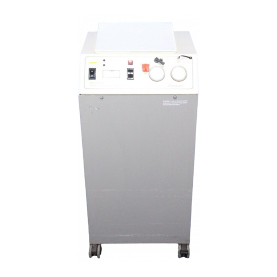
Water Quality Chart Move the selector switch and read the water quality meter. Find the chart column closest to the actual meter reading and read down for the conductivity in microsiemens (µS/cm) and approximate total dissolved solids (TDS) in parts per million (ppm) or for percent rejection. - Page 8 Figure 2: Rear view of RO unit...
-
Page 9: Operator's Controls
WARNING: Never operate the ExtraPure RO System with the needle in the red zone. The three-position selector switch allows the meter to display the water quality of either the recirculating water or the product water. Consult the water quality chart to determine conductivity in microsiemens (µS/cm) and total dissolved solids in parts per... - Page 10 Figure 3: RO Flow Diagram...
-
Page 11: Flow Diagram Component Identification
Flow Diagram Component Identification Component Purpose Solenoid valve Opens to allow water to enter the RO. Closes when the unit is turned off. It ensures that the disinfectant used in disinfecting the unit remains inside the instrument until it is turned on again. Water pressure Located before and after the water filter. -
Page 12: Specification
Specifications Name ExtraPure Reverse Osmosis System Electrical supply 117 VAC 60/50 Hz or 230 VAC 60/50 Hz, 580 W, 6.5 A/3.3 A Incoming water supply pressure 20-100 psi (138-690 kPa) Filter 5-micron carbon filter (P/N 407-8502-014) Maximum water hardness without... -
Page 13: Startup
The ExtraPure RO System must be disinfected prior to use. Follow procedures on page 16 and page 17 or according to your clinic’s recommendation. -
Page 14: Installing
Installing The ExtraPure RO System's hoses are shipped with caps on them. Remove these caps before connecting the hoses. 1. Connect the input hose to the water supply. The connection is a 3/4" female garden hose connection. Use rubber washers on all connections. -
Page 15: Initial Rinse
ON/OFF switch on the control panel. Look for water flowing through the drain line and sanitize hose. 3. Run the ExtraPure RO System for 15 minutes to rinse the fluid path. After 15 minutes, turn off the unit to install the filter in its blue housing. - Page 16 5. Lower the rinse lever. After a few minutes, water quality should be normal and the water quality meter on the control panel should read in the green zone (above 90% rejection). 6. Use the three-position selector switch Product ____________ on the control panel to determine the % Rejection _________ values of the product and the...
-
Page 17: Normal Operation
ExtraPure RO System to the dialysis machine. 2. Turn on the water and turn on the ExtraPure RO System. 3. Note the filter pressure readings at the beginning of use. The difference between filter/inlet pressure and filter/outlet pressure should always be less than 10 psi with no water pressure alarm. -
Page 18: Cleaning The Membrane
7. Turn on the water supply and plug in the ExtraPure RO System. Run the unit for 15 minutes with the rinse lever on the control panel in the rinse position. After rinsing,... - Page 19 Figure 4: Filter assembly...
-
Page 20: Sanitization And Storage Procedure
(If storage time will be more than three days, remove filter and housing, and allow to air-dry. 5. Turn off the ExtraPure RO System and turn off the feed water. Let the RO unit stand with the Formalin™ disinfectant in it until rinsing, according to your dialysis regimen and your clinic's recommendation. -
Page 21: Sanitizing A Hydrogen Peroxide / Peroxyacetic Acid Disinfectant
WARNING: Store all Disinfectants out of reach of children. 1. With the unit off, disconnect the water line connecting the ExtraPure RO System to the dialysis machine. In its place, connect the sanitize hose. Collect at least 50 cc of product water from the sanitizing hose. - Page 22 4. Turn off the ExtraPure RO System and turn off the feed water. Let the RO unit stand idle until rinsing, according to your clinic’s recommendation. The disinfectant must dwell in the system for two hours. Notice: Damage to the system may result if the dwell time is longer than two hours and the membrane is fouled by one of the following conditions: 1.
-
Page 23: Rinsing
Rinsing WARNING: After sanitizing, you must rinse the ExtraPure RO System before using it to supply dialysis water. 1. Turn on the feed water. • Lift the rinse lever on the control panel to the RINSE position. • Turn on the ExtraPure RO System. -
Page 24: Maintenance
If leaks cannot be corrected, call Baxter Instrument Services 1-800-553-6898. External Cleaning Clean the outside of the ExtraPure RO System cabinet with a solution of water and a mild detergent. If additional cleaning is needed, use a solution of half water and half household bleach. -
Page 25: Troubleshooting
TROUBLESHOOTING Basic troubleshooting procedures are given below. If these procedures do not correct the problem, call Baxter Instrument Services at 1-800-553-6898. Alarms SYMPTOM PROBABLE CAUSE CORRECTIVE ACTION Product alarm High product TDS caused by a Change the membrane. torn membrane. -
Page 26: Flow
Meter indication or Meter, PCB, thermistor, wiring, Clean, calibrate or replace logic inaccurate 3 position switch, product water as necessary, or call Baxter LED, Sonalert alarm, Instrument Services. conductivity cells RO recirculation cell is Meter, PCB, power supply, Clean, calibrate or replace <... -
Page 27: Pressure
Water quality not in Meter, PCB, power supply, Clean, calibrate or replace green, but quality is electrodes, thermistor, RO as necessary, or call Baxter good module/vessel, filter, wiring Instrument Services. Water quality meter Open electrical connection in... - Page 28 SYMPTOM PROBABLE CAUSE CORRECTIVE ACTION % rejection indicator is Incoming TDS is less than 150 Install a 5K resistor in in the red zone, ppm (calculated % rejection is parallel with the audible alarm. less than 80%). recirculation conductivity cell. Membrane is scaling.
-
Page 29: Calibration Of Electronics
Calibration of Electronics CAUTION: The following procedure should only be performed by a qualified technician. Call Baxter Instrument Service at 1-800-553-6898. % Rejection Meter Adjustment R55: For the recirculation cell, substitute a 4K resistor (10% or better). For the product cell, substitute a 20K resistor. Adjust R55 so that the meter rests on the red-yellow border. - Page 30 5. Using a flat blade screwdriver, remove the top snap-ring holding the top cap in place. Slowly pull the cap out of the top of the vessel using a rocking motion. 6. Remove the bottom snap-ring and end cap as in previous step. (This step is not necessary if you are able to remove the membrane through the top without difficulty.) 7.
-
Page 31: Pressure Adjustments For Hydrogen Peroxide/Peroxyacetic Acid Compatible System
Pressure Adjustments for Hydrogen Peroxide/Peroxyacetic Acid Compatible System CAUTION: The following procedure should only be performed by a qualified technician. Call Baxter Instrument Service at 1-800-553-6898. 1. Remove hole plugs in the conductivity cell block while the RO unit is off. 2. Install: "AA"... -
Page 32: Pressure Adjustments For Formalin™ Compatible System
Pressure Adjustments for Formalin™ Compatible System CAUTION: The following procedure should only be performed by a qualified technician. Call Baxter Instrument Service at 1-800-553-6898. 1. Remove hole plugs in the conductivity cell block while the RO unit is off. 2. Install: "AA"... -
Page 33: Conductivity Cell Connections
Conductivity Cell Connections Damage or loosening of these connections could render the conductivity cell useless and result in erroneous water quality readings. The following are results obtained by simulating conductivity cell failure. Conditions % Rejection Product Recirculation Product cell open pegged right pegged right normal... -
Page 34: Diagrams And Schematics
DIAGRAMS AND SCHEMATICS The following diagrams and schematics are contained in this section: ExtraPure RO Wiring Diagram, 157-1232-996 ExtraPure RO System Schematic Diagram, 157-1232-997 Logic-Conductivity Circuit, 157-1232-994...
Need help?
Do you have a question about the ExtraPure and is the answer not in the manual?
Questions and answers