Table of Contents
Advertisement
Quick Links
We advise you to read this manual carefully, as it contains all the instructions for maintaining
the appliance's aesthetic and functional qualities.
For further information on the product: www.smeg.com
Table of contents
ORIGINAL INSTRUCTIONS
52
52
57
57
57
57
57
58
59
59
60
60
61
62
63
63
65
66
67
69
72
73
76
76
76
77
78
80
81
83
84
84
87
92
97
98
51
Advertisement
Table of Contents

Related Manuals for Smeg GP61X9


Summary of Contents for Smeg GP61X9
-
Page 1: Table Of Contents
5.3 Positioning 5.4 Electrical connection 5.5 Instructions for the installer ORIGINAL INSTRUCTIONS We advise you to read this manual carefully, as it contains all the instructions for maintaining the appliance’s aesthetic and functional qualities. For further information on the product: www.smeg.com... -
Page 2: Instructions
Instructions 1 Instructions • Keep children under the age of 8 away from the appliance when 1.1 General safety instructions it is in use. • Cleaning and maintenance must Risk of personal injury not be carried out by • During use the appliance and its unsupervised children. - Page 3 Instructions • While cooking do not place • DO NOT USE AEROSOLS IN metal objects, such as cutlery or THE VICINITY OF THIS dishes on the hob surface as they APPLIANCE WHILST IT IS IN may overheat. USE. • Do not insert pointed metal •...
- Page 4 Instructions Risk of damaging the appliance • DO NOT USE THE APPLIANCE TO HEAT ROOMS FOR ANY • Do not use abrasive or corrosive REASON. detergents (e.g. scouring • Do not spray any spray products powders, stain removers and near the oven. metallic sponges) on glass parts.
- Page 5 Instructions • All pans must have smooth, flat • Do not wash the removable bottoms. components such as the hob grids, flame-spreader crowns and • If any liquid does boil over or spill, burner caps in a dishwasher. remove the excess from the hob. •...
- Page 6 Instructions • Installation using a hose must be • Use cables withstanding a carried out so that the length of temperature of at least 90 °C. the hose does not exceed • The tightening torque of the 2 metres when fully extended for screws of the terminal board steel hoses and 1.5 metres for leads must be 1.5 - 2 Nm.
-
Page 7: Manufacturer Liability
Instructions 1.2 Manufacturer liability 1.5 This user manual The manufacturer declines all liability This user manual is an integral part of for damage to persons or property the appliance and must therefore be caused by: kept in its entirety and within the user’s reach for the whole working •... -
Page 8: How To Read The User Manual
Instructions • Deliver the appliance to the 1.7 How to read the user manual appropriate recycling centre for This user manual uses the following reading electrical and electronic conventions: equipment waste, or return it to Instructions the retailer when purchasing an General information on this user equivalent product, on a one for manual, on safety and final... -
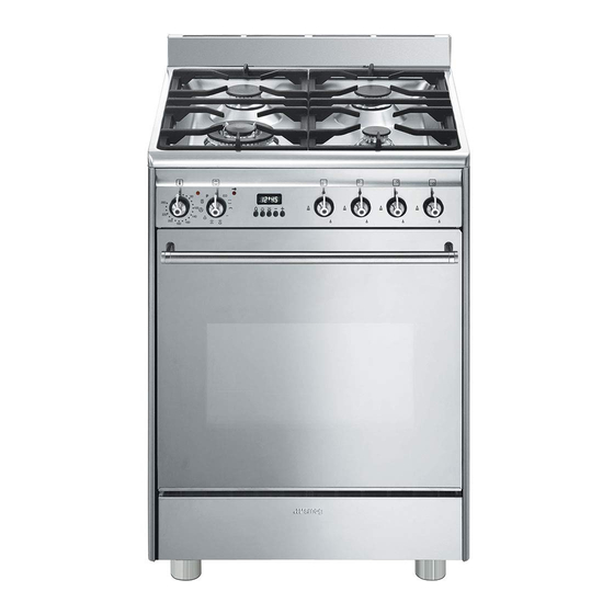
Page 9: Description
Description 2 Description 2.1 General Description 1 Cooking hob 5 Door 2 Control panel 6 Fan 3 Light bulb 7 Storage compartment 4 Seal Rack/tray support frames... -
Page 10: Cooking Hob
Description 2.2 Cooking hob AUX = Auxiliary burner UR-3c = Ultra-rapid burner SR = Semi-rapid burner 2.3 Control panel 1 Temperature knob 2 Indicator light This knob allows you to select the cooking The indicator light comes on to indicate that temperature. -
Page 11: Other Parts
Description 2.4 Other parts 3 Function knob The oven’s various functions are suitable for Shelves different cooking modes. After selecting the The appliance features shelves to position required function, set the cooking trays and racks at different heights. The temperature using the temperature knob. insertion heights are indicated from the 4 Door lock indicator light bottom upwards (see 2.1 General... -
Page 12: Available Accessories
Description 2.5 Available accessories Deep tray Rack Useful for collecting fat from foods placed on the rack above and for cooking pies, pizzas and baked desserts. Not all accessories are available on some models. The oven accessories intended to come into contact with food are made of materials that comply with the provisions of current legislation. -
Page 13: Use
3 Use High temperature inside the storage compartment 3.1 Instructions Danger of burns High temperature inside the oven • Do not open the storage compartment during use when the appliance is on and still hot. Danger of burns • The items inside the storage compartment could be very hot after •... - Page 14 Precautions High temperature inside the storage compartment A gas leak can cause an explosion. Danger of fire or explosion If you smell gas or there are faults in the gas system: • Do not spray any spray product near the •...
-
Page 15: Using The Accessories
3.2 Using the accessories First use 1. Remove any protective film from the Racks and trays outside or inside of the appliance, Racks and trays have to be inserted into the including accessories. side guides until they come to a complete 2. -
Page 16: Using The Hob
3.3 Using the hob Correct positioning of the flame- spreader crowns and burner caps All the appliance’s control and monitoring devices are located together on the front Before lighting the hob burners, make sure panel. The burner controlled by each knob that the flame-spreader crowns are correctly is shown next to the knob. -
Page 17: Using The Oven
3.4 Using the oven Functions list Switching on the oven This function is particularly suitable To switch the oven on: for cooking on a single shelf with 1. Select the cooking function using the low energy consumption. function knob. It is recommended for all types of 2. - Page 18 Static Fan assisted As the heat comes from above and The operation of the fan, combined below at the same time, this system with traditional cooking, ensures is particularly suitable for certain consistent cooking even with types of food. Traditional cooking, complex recipes.
-
Page 19: Programmer Clock
3.5 Programmer clock Fan with round heating element The combination of the fan and the round heating element (incorporated in the rear of the oven) allows you to cook different foods on several levels, as long as they need the same temperatures and same type of cooking. - Page 20 Timed cooking Setting the time Timed cooking is the function If the time is not set, the oven will which allows a cooking operation not switch on. to be started and then ended after a specific length of time set by the On the first use, or after a power failure, the user.
- Page 21 5. To turn off the buzzer just press any key 4. Wait approx. 5 seconds without pressing of the programmer clock. any key in order for the function to activate. The current time and the 6. Press the keys at the same symbols will appear on the time to reset the programmer clock.
-
Page 22: Using The Storage Compartment
Deleting the set data Minute minder timer Press the keys at the same The minute minder timer does not stop the cooking operation but time to reset the programs set. rather informs the user when the set Then switch off the oven manually if cooking time has run out. -
Page 23: Cooking Advice
3.7 Cooking advice • When using the Fan with grill function, we recommend that you preheat the General advice oven before grilling. • Use a fan assisted function to achieve • We recommend placing the food at the consistent cooking at several levels. centre of the rack. - Page 24 Advice for defrosting and proving To save energy • Place frozen foods without their • Stop cooking a few minutes before the packaging in a lidless container on the time normally used. Cooking will first shelf of the oven. continue for the remaining minutes with the heat which has accumulated inside •...
- Page 25 Cooking information table Weight Temperature Food Function Shelf Time (minutes) (kg) (°C) Lasagne 3 - 4 Static 220 - 230 45 - 50 Pasta bake 3 - 4 Static 220 - 230 45 - 50 Roasted veal Turbo/Round 180 - 190 90 - 100 Pork loin Turbo/Round...
-
Page 26: Cleaning And Maintenance
Cleaning and maintenance 4 Cleaning and maintenance Ordinary daily cleaning Always use specific products only that do 4.1 Instructions not contain abrasives or chlorine-based acids. Improper use Pour the product onto a damp cloth and Risk of damage to surfaces wipe the surface, rinse thoroughly and dry with a soft cloth or a microfibre cloth. -
Page 27: Cleaning The Hob
Cleaning and maintenance 4.3 Cleaning the hob Flame-spreader crowns and burner caps For easier cleaning, the flame-spreader Knobs crowns and the burner caps can be removed. Wash them in hot water and non- Do not use aggressive products abrasive detergent. Carefully remove any containing alcohol or products for encrustation, then wait until they are cleaning steel and glass when... -
Page 28: Cleaning The Door
Cleaning and maintenance 4.4 Cleaning the door 3. To reassemble the door, put the hinges in the relevant slots in the oven, making sure Removing the door that grooved sections A are resting For easier cleaning, the door can be completely in the slots. - Page 29 Cleaning and maintenance Removing the internal glass panes 4. Clean the external glass pane and the previously removed panes. Use For easier cleaning, the internal glass panes absorbent kitchen roll. In case of of the door can be removed. stubborn dirt, wash with a damp sponge 1.
-
Page 30: Cleaning The Oven Cavity
Cleaning and maintenance 4.5 Cleaning the oven cavity Cleaning of racks and trays For the best oven cavity upkeep, clean it Clean the racks and trays with warm water regularly after having allowed it to cool. and non-abrasive detergents. Carefully rinse and dry damp parts. -
Page 31: Pyrolytic
Cleaning and maintenance 4.6 Pyrolytic • For very stubborn encrustations spray an oven cleaning product onto the glass Pyrolytic cleaning is an automatic (read the warnings on the product); high-temperature cleaning leave for 60 minutes, then rinse and dry procedure which causes dirt to the glass using kitchen roll or a microfibre dissolve. - Page 32 Cleaning and maintenance Setting of programmed pyrolytic cycle During the first pyrolytic cycle, The pyrolytic cycle start time can be unpleasant odours may occur due programmed using the programmer clock. to the normal evaporation of oily manufacturing substances. This is 4.
-
Page 33: Extraordinary Maintenance
Cleaning and maintenance 4.7 Extraordinary maintenance 4. Slide out and remove the light bulb. Replacing the internal light bulb Live parts Danger of electrocution • Unplug the appliance from the mains. • Wear protective gloves. 1. Remove all accessories from inside the oven cavity. -
Page 34: Installation
Installation 5 Installation General information Connection to the gas mains can be made 5.1 Gas connection (not valid for the using a continuous wall steel hose in compliance with the guidelines established by the standards in force. The appliance is For installation in the UK, please preset for natural gas G20 (2H) at a refer to the “Local specifications for... - Page 35 Installation Carefully screw the hose connector 3 to the Connection with a steel hose appliance’s gas connector 1 (½” thread Make the connection to the gas mains ISO 228-1), placing the seal 2 between using a continuous wall steel hose whose them.
- Page 36 Installation Connection to LPG Room ventilation Use a pressure regulator and make the This appliance is not connected to connection on the gas cylinder following an exhaust system for combustion the guidelines set out in the standards in products. It must be installed and force.
-
Page 37: Adaptation To Different Types Of Gas
Installation 5.2 Adaptation to different types of gas Improper installation Risk of malfunction • In the case of conversion to Town Gas G110 – 8 mbar (category 1a), do not use the burners provided, but request the special G110 burners kit from our Technical Assistance Service. - Page 38 Installation (see "Nozzle and burner specification Adjusting the minimum setting for LPG tables"). Tighten the screw located at the side of the cock rod clockwise all the way. Following adjustment to a gas other than the one originally set in the factory, replace the gas setting label on the appliance with the one corresponding to the new gas.
- Page 39 Installation Gas types and Countries Gas types EN GB-IE FR-BE DE AT NL ES PT SE RU DK PL HU 1 Natural gas G20 • • • • • • • • • • 20 mbar • G20/25 20/25 mbar 2 Natural gas G20 •...
- Page 40 Installation Burner and nozzle characteristics tables 1 Natural gas G20 - 20 mbar UR-3c Rated heating capacity (kW) 1.05 Nozzle diameter (1/100 mm) Pre-chamber (printed on nozzle) Reduced flow rate (W) 1600 2 Natural gas G20 - 25 mbar UR-3c Rated heating capacity (kW) 1.05 Nozzle diameter (1/100 mm)
- Page 41 Installation 7 LPG G30/31 - 30/37 mbar UR-3c Rated heating capacity (kW) 1.05 Nozzle diameter (1/100 mm) Pre-chamber (printed on nozzle) Reduced flow rate (W) 1600 Rated flow rate G30 (g/h) Rated flow rate G31 (g/h) 8 LPG G30/31 - 37 mbar UR-3c Rated heating capacity (kW) Nozzle diameter (1/100 mm)
-
Page 42: Positioning
Installation 5.3 Positioning Any wall units positioned above the worktop of the appliance must be at a Heavy appliance minimum distance of at least Y mm. If a Crushing hazard hood is installed above the hob, refer to the hood instruction manual to ensure the correct clearance is left. - Page 43 Installation Appliance overall dimensions 600 mm 600 mm B - Class 2 subclass 1 min. 150 mm (Built-in appliance) 900 - 915 mm 750 mm 450 mm 600 mm Minimum distance from side walls or other flammable material. Minimum cabinet width (=A). C - Class 2 subclass 1 (Built-in appliance) The appliance must be installed by...
- Page 44 Installation Dimensions of the appliance: locations of Positioning and levelling gas and electric connections (mm) Heavy appliance Risk of damage to the appliance • Insert the front feet first and then the rear ones. After making the electrical and/or gas connections, screw the four adjustable feet supplied with the appliance.
- Page 45 Installation 3. Assemble the fastening bracket. Fastening to the wall The anti-tip devices must be installed in order to prevent the appliance from tipping over. 1. Screw the wall fastening plate to the rear of the appliance. 4. Align the base of the hook on the fastening bracket with the base of the slot on the wall fastening plate.
- Page 46 Installation 5. Align the base of the fastening bracket 7. Move the bracket onto the wall and with the ground and tighten the screws to mark the position of the holes to be fix the measurements. drilled in the wall. 8.
-
Page 47: Electrical Connection
Installation 5.4 Electrical connection Assembling the skirt The skirt provided is an integral Power voltage part of the product; it must be Danger of electrocution fastened to the appliance prior to installation. • Have the electrical connection performed by authorised technicians. The skirt must always be positioned and •... -
Page 48: Instructions For The Installer
Installation The appliance can work in the following 5.5 Instructions for the installer modes: • The plug must be accessible after • 220-240 V 1N~ installation. Do not bend or trap the power cable. • The appliance must be installed according to the installation diagrams.
Need help?
Do you have a question about the GP61X9 and is the answer not in the manual?
Questions and answers