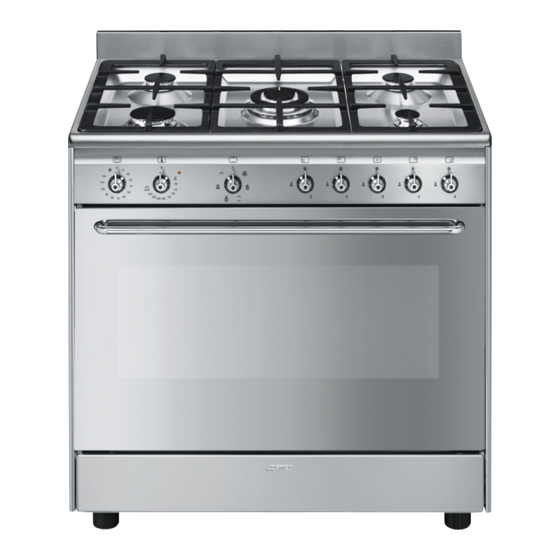
Smeg FS9010XS Manual
Hide thumbs
Also See for FS9010XS:
- User manual (48 pages) ,
- User manual (40 pages) ,
- User manual (44 pages)
Table of Contents
Advertisement
We advise you to read this manual carefully, which contains all the instructions for
maintaining the appliance's aesthetic and functional qualities.
For further information on the product: www.smeg.com
Contents
4
4
8
9
9
9
9
10
11
11
12
12
13
13
15
15
16
17
18
19
20
23
23
23
24
25
25
27
28
31
31
31
33
35
40
41
3
Advertisement
Table of Contents

Related Manuals for Smeg FS9010XS


Summary of Contents for Smeg FS9010XS
-
Page 1: Table Of Contents
5.3 Adaptation to different types of gas 5.4 Positioning 5.5 Electrical connection 5.6 For the installer We advise you to read this manual carefully, which contains all the instructions for maintaining the appliance's aesthetic and functional qualities. For further information on the product: www.smeg.com... -
Page 2: Instructions
Instructions 1 Instructions appliance when in operation. • Young children should be 1.1 General safety instructions supervised to ensure that they do not play with the appliance. Risk of personal injury • During use the appliance • During use the appliance becomes hot. - Page 3 Instructions their housings with their respective compartment (if present) when the burner caps. oven is on and still hot. • Be aware of how rapidly the • The items inside the storage cooking zones heat up. Do not compartment could be very hot place empty pans on the heat.
- Page 4 Instructions • If the power supply cable is may result in shattering of the damaged, contact technical glass. support immediately and they will • Never leave objects on the replace it. cooking surface. • DO NOT USE THE APPLIANCE Risk of damaging the appliance AS A SPACE HEATER.
- Page 5 Instructions • If any liquid does boil over or spill, move the appliance. remove the excess from the • NOT SUITABLE WITH cooktop. AFTERMARKET LIDS OR • Take care not to spill acidic COVERS. substances such as lemon juice or Installation vinegar onto the cooktop.
-
Page 6: Identification Plate
Instructions check that the tightening torque of be 1.5 - 2 Nm. gas connections is between 10 Nm • If this appliance is installed on a and 15 Nm. base, measures must be taken to • At the end of the installation, check prevent the appliance from for any leaks with a soapy slipping from the base. -
Page 7: Manufacturer Liability
Instructions 1.3 Manufacturer liability 1.6 How to read the user manual This user manual uses the following reading The manufacturer declines all liability conventions: for damage to persons or property caused by: Instructions • use of the appliance other than General information on this user manual, on safety and final the one envisaged;... -
Page 8: To Save Energy
Instructions 1.7 To save energy • Only preheat the appliance if the recipe requires you to do so. • Unless otherwise indicated on the package, defrost frozen foods before placing them in the oven. • When cooking several types of food it is recommended to cook the foods one after the other to make the best use of the already... -
Page 9: Description
Description 2 Description 2.1 General Description 1 Backguard 6 Door 2 Cooktop 7 Fan 3 Control panel 8 Toe skirt (on some models only) 4 Oven light Rack/tray support frame shelf 5 Seal... -
Page 10: Cooktop
Description 2.2 Cooktop AUX = Auxiliary R = Rapid SR = Semi-rapid UR = Ultra rapid 2.3 Control panel 1 Minute minder timer knob 3 Indicator light Allows you to set manual cooking or a timer The indicator light comes on to indicate that with automatic oven switch off at the end of the oven is heating up. -
Page 11: Other Parts
Description Turn the knobs to the zone between the Interior lighting maximum and minimum setting to The appliance interior lighting comes on: adjust the flame. • When the door is opened • When any function is selected Return the knobs to the position to turn off the burners. - Page 12 Description Rack Useful for supporting containers with food during cooking. Oven tray Useful for collecting fat from foods placed on the rack above. The accessories intended to come into contact with food are made of materials that comply with the provisions of current legislation.
-
Page 13: Use
3 Use Improper use Risk of damage to surfaces 3.1 Instructions High temperature inside the oven • Do not cover the bottom of the oven during use cavity with aluminium or tin foil sheets. Danger of burns • If you wish to use greaseproof paper, place it so that it will not interfere with the •... -
Page 14: First Use
Abnormal operation High temperature inside the oven during use Any of the following are considered to be abnormal operation and may require Danger of fire or explosion service: • Do not spray any spray products near • Yellow tipping of the hotplate burner the oven. -
Page 15: Using The Accessories
3.3 Using the accessories Ring reducers The ring reducers have to be placed on the Racks and trays cooktop grids. Make sure they are placed Racks and trays have to be inserted into the properly. side guides until they come to a complete stop. -
Page 16: Using The Cooktop
3.4 Using the cooktop Correct positioning of the flame- spreader crowns and burner caps All the appliance's control and monitoring devices are located together on the front Before lighting the cooktop burners, make panel. The burner controlled by each knob sure that the flame-spreader crowns are is shown next to the knob. -
Page 17: Using The Oven
3.5 Using the oven Functions list Switching on the oven Fan forced The combination of the fan and the To switch on the oven: circular heating element 1. Select manual cooking or set the (incorporated in the rear of the cooking duration using the timer knob. -
Page 18: Cooking Advice
3.6 Cooking advice Baker’s function The combination of the fan with just General advice the lower heating element allows • Use a fan assisted function to achieve cooking to be completed more consistent cooking at several levels. rapidly. This system is •... - Page 19 Advice for cooking desserts/pastries and biscuits • Use dark metal moulds: they help to absorb the heat better. • The temperature and the cooking time depend on the quality and consistency of the dough. • To check whether the dessert is cooked right through: at the end of the cooking time, put a toothpick into the highest point of the dessert.
- Page 20 Cooking information table Runner posi- Weight Temperature Food Function tion from the Time (minutes) (Kg) (°C) bottom Lasagne 3 - 4 Convection 220 - 230 45 - 50 Pasta bake 3 - 4 Convection 220 - 230 45 - 50 Roast veal Fan assisted/Fan forced 180 - 190...
-
Page 21: Cleaning And Maintenance
Cleaning and maintenance 4 Cleaning and maintenance Cleaning the cooktop 1. Pour some non-abrasive detergent on a 4.1 Instructions damp cloth and wipe down the surfaces. 2. Rinse thoroughly. Improper use Risk of damage to surfaces 3. Dry with a soft cloth or a microfibre cloth. Cleaning the cooktop grids, flame- •... -
Page 22: Removing The Door
Cleaning and maintenance a toothpick or needle. 4.3 Removing the door For easier cleaning, the door can be removed and placed on a tea towel. To remove the door proceed as follows: 1. Open the door completely and insert two pins into the holes on the hinges indicated in the figure. -
Page 23: Cleaning The Door Glazing
Cleaning and maintenance 3. To reassemble the door, put the hinges in 4.5 Removing the internal glass panes the relevant slots in the oven, making sure For easier cleaning the door internal glass that grooved sections A are resting panes can be disassembled. completely in the slots. - Page 24 Cleaning and maintenance 4. Clean the external glass pane and the Removing racks/trays support frames panes previously removed. Use Removing the guide frames enables the absorbent kitchen roll. In case of sides to be cleaned more easily. This stubborn dirt, wash with a damp sponge operation should be performed each time and neutral detergent.
-
Page 25: Vapour Clean
Cleaning and maintenance 4.6 Vapour Clean • Pour approximately 40 cc of water into the tray. Make sure it does not overflow Vapour Clean is an assisted out of the cavity. cleaning procedure which facilitates the removal of dirt. Thanks to this process, it is possible to clean the inside of the oven very easily. -
Page 26: Extraordinary Maintenance
Cleaning and maintenance Vapour Clean setting 4.7 Extraordinary maintenance 1. Turn the function knob to the symbol Removing and installing the oven seal To remove the oven seal: the temperature knob to the symbol • Unhook the clips in the 4 corners and in 2. - Page 27 Cleaning and maintenance 2. Remove the racks/trays support frames. 6. Refit the cover. Ensure the moulded part of the glass (A) is facing the door. 3. Remove the bulb cover using a tool (e.g. a screwdriver). Pay attention not to scratch the oven cavity enamel.
- Page 28 Cleaning and maintenance The oven does not heat up. • Faulty fuse: check and, if required, replace the circuit breaker. • The function knob has not been set: set the function knob. All dishes that are prepared in the oven burn within an extremely short period of time.
-
Page 29: Installation
Installation 5 Installation 5.2 Gas connection 5.1 Minimum clearance to Gas leak combustible surfaces Danger of explosion Freestanding cooker • After carrying out any operation, check that the tightening torque of gas connections is between 10 Nm and 15 • If required, use a pressure regulator that complies with current regulations. - Page 30 Gas pressure must be adjusted to 1.0 kPa when approximately 50% of the burners are on high flame, the appliance test point is located on the regulator. Patent 2015101170. For enquires contact Gas Approval Consulting Pty Ltd Smeg licence 037 for GSCS20265...
-
Page 31: Adaptation To Different Types Of Gas
Installation Room ventilation C Directly outdoors with wall- or window- mounted extractor fan. The room containing the appliance should D Directly outdoors through wall. have a permanent air supply in accordance with the standards in force. The room where the appliance is installed must have enough Combustion products air flow needed for the regular combustion Extractor fan... - Page 32 Installation Adjusting the minimum setting for natural Adjusting the minimum setting for LPG or city gas Tighten the screw located at the side of the Light the burner and turn it to the minimum cock rod clockwise all the way. position.
-
Page 33: Positioning
Installation Burner and nozzle characteristics table 1 ULPG 2.75 kPa Nominal gas consumption (MJ/h) 10.8 Injector (1/100 mm) 2 NG 1.0 kPA Nominal gas consumption (MJ/h) 15.8 Injector (1/100 mm) 5.4 Positioning Overall dimensions Heavy appliance Location of gas and electrical connection Danger of crush injuries points. - Page 34 Installation The appliance must sit level on the floor to Positioning and levelling ensure stability. Heavy appliance • Screw or unscrew the bottom part of the Risk of damage to the appliance foot until the appliance is stable and level on the floor. •...
- Page 35 Installation 2. Adjust the height of the 4 feet. 4. Align the base of the hook on the fastening bracket with the base of the slot on the wall fastening plate. 3. Assemble the fastening bracket. 5. Align the base of the fastening bracket with the ground and tighten the screws to fix the measurements.
- Page 36 Installation 6. Use 50 mm for the distance from the side 9. Push the cooker towards the wall, and at of the appliance to the bracket holes. the same time, insert the bracket in the plate fastened to the rear of the appliance.
- Page 37 Installation 2. Attach the chain to the cooker with the 6. Attach the chain and push the appliance screw just removed. to the wall. The chain length must be as short as practicable to avoid appliance tilting forward and also diagonal to avoid appliance moving 3.
-
Page 38: Electrical Connection
Installation 3. Secure the upstand to the worktop by 3. Fasten the toe skirt using the screws that tightening the screws A. were previously removed. 5.5 Electrical connection Power voltage Danger of electrocution • Have the electrical connection performed by authorised technical personnel. -
Page 39: For The Installer
Cleaning and maintenance Perform the ground connection using a wire 5.6 For the installer that is 20 mm longer than the other wires. • The plug must remain accessible after the The appliance can work in the following installation is complete. Do not kink or modes: trap the mains connection cable.
Need help?
Do you have a question about the FS9010XS and is the answer not in the manual?
Questions and answers
The oven does not work
The Smeg FS9010XS oven may not be working due to the following reasons:
1. Faulty Fuse – Check and replace the circuit breaker if needed.
2. Power Cut – Verify if the kitchen light works to confirm a power supply issue.
3. Function Knob Not Set – Ensure the function knob is properly adjusted.
4. Thermostat Issue – If all dishes burn quickly, the thermostat may be faulty, requiring professional assistance.
These checks can help diagnose and resolve the issue.
This answer is automatically generated