Advertisement

Quick Links

Advertisement

Table of Contents
loading

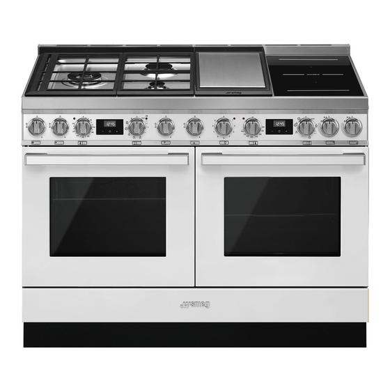
Summary of Contents for Smeg Portofino Aesthetic CPF120IGMPWH

  • Page 1: Table Of Contents

    5.2 Adaptation to different types of gas 5.3 Positioning 5.4 Electrical connection 5.5 Instructions for the installer We advise you to read this manual carefully, which contains all the instructions for maintaining the appliance’s aesthetic and functional qualities. For further information on the product: www.smeg.com...
  • Page 2: Instructions

    Instructions 1 Instructions • Keep children under the age of 8 away from the appliance when it 1.1 General safety instructions is in use. • Cleaning and maintenance must Risk of personal injury not be carried out by unsupervised • During use the appliance and its children.
  • Page 3 Instructions • Do not place metal objects, such • DO NOT USE AEROSOLS IN as dishes or cutlery, on the hob THE VICINITY OF THIS surface during use as they may APPLIANCE WHILST IT IS IN overheat. USE. • Do not insert pointed metal objects •...
  • Page 4 Instructions Risk of damaging the appliance • Do not spray any spray products near the oven. • Use wooden or plastic utensils. • Do not use plastic cookware or • Racks and trays should be inserted containers when cooking food. as far as they will go into the side •...
  • Page 5 Instructions • Take care not to spill acid • If cracks or fissures form, or if the substances such as lemon juice or glass ceramic cooking surface vinegar on the hob. breaks, turn off the appliance immediately. Disconnect the • Do not put empty pans or frying power supply and call Technical pans on switched on cooking Support.
  • Page 6 Instructions • To avoid potential overheating, the • Use PVC cables that can withstand appliance must not be installed temperatures of at least 90°C. behind a decorative door or a • The tightening torque of the screws panel. of the terminal supply wires must •...
  • Page 7: Identification Plate

    Instructions • The maximum capacity of the 1.5 This user manual evaporation tray is 250 ml. This user manual is an integral part of • Be very careful not to exceed the the appliance and must therefore be maximum capacity of the kept in its entirety and within the evaporation tray.
  • Page 8: How To Read The User Manual

    Instructions • Deliver the appliance to the 1.7 How to read the user manual appropriate recycling centre for This user manual uses the following reading electrical and electronic conventions: equipment waste, or return it to Instructions the retailer when purchasing an General information on this user equivalent product, on a one for manual, on safety and final...
  • Page 9: To Save Energy

    Instructions 1.8 To save energy • Only preheat the appliance if the recipe requires you to do so. • Unless otherwise indicated on the package, defrost frozen foods before placing them in the oven. • When cooking several types of food it is recommended to cook the foods one after the other to make the best use of the already...
  • Page 10: Description

    Description 2 Description General description 1 Hob 7 Humidified oven door 2 Control panel 8 Fans 3 Seals 9 Storage compartment 4 Inside lights 10 Evaporation tray 5 Temperature probe socket Rack/tray support frame shelf 6 Pyrolytic oven door...
  • Page 11: Hob

    Description 2.1 Hob SR = Semi-Rapid Burner UR2 int. = Internal Ultra Rapid Burner crown R = Rapid Burner UR2 ext. = External Ultra Rapid Burner BBQ = Barbecue plate crown 1 = Front Induction cooking zone 2 = Rear Induction cooking zone Dimensions Max.
  • Page 12: Control Panel

    Description 2.2 Control panel 1 Hob burner knobs 5 - 12 Programmer clock For lighting and adjusting the hob burners. For displaying the current time, setting Press and turn the knobs anti-clockwise programmed cooking and the minute minder timer. in order to light the relative burners. Turn the knobs to the zone between the 6 - 13 Function knob maximum...
  • Page 13: Other Parts

    Description 10 Indicator light Available accessories The indicator light comes on to indicate that Oven tray the oven is heating up. It turns off as soon as it reaches the set temperature. It flashes regularly to indicate that the temperature set inside the oven is kept constant.
  • Page 14 Description Tray rack Temperature probe (pyrolytic oven) With the temperature probe, you can cook according to the temperature measured at the centre the food. To be placed over the top of the oven tray; Protective cover (pyrolytic oven) for cooking foods which may drip. Rack Useful for supporting containers with food Used to cover and protect the temperature...
  • Page 15: Use

    3 Use Improper use Danger of burns Instructions High temperature inside the oven • Make sure that the flame-spreader during use crowns are correctly positioned in their housings with their respective burner Danger of burns caps. • Keep the oven door closed during •...
  • Page 16: First Use

    3.1 First use Improper use 1. Remove any protective film from the Risk of damage to surfaces outside or inside of the appliance, including accessories. • Do not cover the bottom of the oven 2. Remove any labels (apart from the cavity with aluminium or tin foil sheets.
  • Page 17: Using The Gas Hob

    Racks and trays 3.3 Using the gas hob All the appliance’s control and monitoring Racks and trays have to be inserted into the devices are located together on the front side guides until they come to a complete panel. The burner controlled by each knob stop.
  • Page 18: Using The Induction Hot Plates

    Correct positioning of the flame- 3.4 Using the induction hot plates spreader crowns and burner caps After use, turn off the hot plates Before lighting the hob burners, make sure used by returning the appropriate that the flame-spreader crowns are knob to the O position.
  • Page 19 To see whether the pan is suitable, bring a Cookware recognition magnet close to the bottom: if it is attracted, When there is no saucepan on a cooking the pan is suitable for induction cooking. If zone or if the saucepan is too small, no you do not have a magnet, you can put a energy will be transmitted and the small amount of water in the pan, place it...
  • Page 20 Limiting the cooking duration Power levels The hob has an automatic device which The power in the cooking zone can be limits the duration of use. adjusted to various levels. The table shows the levels suitable for various types of If the cooking zone settings are not cooking.
  • Page 21 Heating accelerator Multizone function Each cooking zone is equipped This function can be used to with a heating accelerator that operate two allows the maximum power to be cooking zones (front and rear) delivered for a time that is simultaneously proportional to the selected when using pans like fish kettles or power.
  • Page 22 3. Use the front cooking zone knob to set Booster function the required power level: this knob now The booster function allows the controls both the cooking zones that are cooking zone to be activated at in use. maximum power for as long as 5 To deactivate the Multizone function: minutes.
  • Page 23: Using The Ovens

    1. Remove the barbecue plate before 3.5 Using the ovens starting cooking. Switching on the ovens 2. Lift heating element A and hold it in place with stop B. To switch on the ovens: 1. Select the cooking function using the function knob.
  • Page 24 The ECO function is recommended Grill for cooking that does not require The heat coming from the grill temperatures higher than 210°C. element gives perfect grilling results It is recommended that you select above all for thin and medium a different function for cooking at thickness meat and, in combination higher temperatures.
  • Page 25 Fan with grill Direct Steam (humidified oven only) The air produced by the fan softens This function activates the central the strong heatwave generated by part of the lower heating element the grill, grilling perfectly even very together with the circulaire heating thick foods.
  • Page 26: Cooking With The Direct Steam Function (Humidified Oven)

    3.6 Cooking with the Direct Steam function (humidified oven) Do not place food or any other object directly on the bottom of the oven. The base of the oven and the evaporation tray must always be left free. 1. Open the oven door. 2.
  • Page 27 End of Direct Steam cooking 5. Use a sponge to remove any condensation from the base and walls 1. Stand to the side of the appliance and of the oven cavity, the door glass and open the door ajar for a few seconds the drip tray at the front of the to allow excess steam to escape.
  • Page 28: Using The Temperature Probe (Pyrolytic Oven)

    3.7 Using the temperature probe (pyrolytic oven) Improper use High temperature of the Risk of injury temperature probe Danger of burns • Do not leave the temperature probe unattended. • Do not touch the rod or the tip of the •...
  • Page 29 The core temperature of the food is Cooking using the temperature probe measured by a sensor located in the tip of With preheating: the probe. 1. Set manual cooking (see “Using the ovens”). Positioning the probe 2. After preheating, open the door and 1.
  • Page 30 4. Close the door. 4. Set the cooking using the probe as indicated in steps 5, 6 and 7 in the 5. Press the button for a few seconds; previous section. Press the button again. The default 5. Set manual cooking by selecting the temperature and cooking function (see target temperature “Using the ovens”).
  • Page 31: Using The Storage Compartments

    At the end of cooking 3.9 Cooking advice When the set target temperature for the General advice temperature probe is reached, the heating • Use a fan assisted function to achieve elements are switched off and the consistent cooking at several levels. appliance emits a series of beeps.
  • Page 32 Advice for cooking with the Grill and the • If the dessert collapses when it comes out Fan with grill of the oven, on the next occasion reduce the set temperature by about 10°C, • Meat can be grilled even when it is put selecting a longer cooking time if into the cold oven or into the preheated necessary.
  • Page 33: Programmer Clock 101

    3.10 Programmer clock Setting the time When using the appliance for the first time or after a power failure, setting the time on one clock will set the same time on the other. If the time is not set, the oven will not switch on.
  • Page 34 Timed cooking 7. Press the clock button to reset the programmer clock. Timed cooking is the function which allows a cooking operation It is not possible to set a cooking to be started and then ended after time of more than 10 hours. a specific length of time set by the user.
  • Page 35 10. Return the function and temperature 4. Press the button to set the knobs to 0. required minutes. (for example 1 hour). 11. To turn off the buzzer just press any 5. Press the menu button . The text button of the programmer clock. will appear on the display in 12.
  • Page 36 Modifying the set data Minute minder timer 1. Press the clock button The minute minder timer does not stop the cooking operation but 2. Use the value increase and value rather informs the user when the set time has run out. decrease buttons to set the number of minutes required.
  • Page 37 Cooking information table Weight Temperature Time Food Function Shelf (minutes) (Kg) (°C) Lasagne 3 - 4 Static 220 - 230 45 - 50 Pasta bake 3 - 4 Static 220 - 230 45 - 50 Veal roast Fan assisted 180 - 190 90 - 100 Pork loin Fan assisted...
  • Page 38 Direct Steam cooking information table Temperature Food Weight (Kg) Water (ml) Shelf Time (minutes) (°C) Lasagne 120 - 130 190 - 200 35 - 40 Pasta bake 1.2 - 1.5 120 - 130 190 - 200 35 - 40 MEAT Roast turkey 190 - 200 80 - 90...
  • Page 39 Temperature Food Weight (Kg) Water (ml) Shelf Time (minutes) (°C) VEGETABLES Roast potatoes 210 - 220 40 - 45 Mixed roasted vegetables REHEATING FOOD Pasta 100 - 110 15 - 25 Sliced roast 100 - 110 15 - 25 meats/spare ribs Bread 100 - 110 15 - 25...
  • Page 40 Probe-cooking information table Target Type and cut of meat temperature (°C) Beef Roast beef: rare 50 - 53 Roast beef: medium 55 - 58 Roast beef: well done 65 - 70 Rib of beef: rare* Rib of beef: medium* Rib of beef: well done* Pork Roast loin 80 - 85...
  • Page 41 Cleaning and maintenance 4 Cleaning and maintenance 4.1 Cleaning the appliance To keep the surfaces in good condition, Instructions they should be cleaned regularly after use. Let them cool first. Improper use Risk of damage to surfaces Ordinary daily cleaning Always and only use specific products that •...
  • Page 42: Cleaning And Maintenance

    Cleaning and maintenance Dirt which may have fallen on the hob Barbecue plate while cleaning lettuce or potatoes can The plate is coated with a non-stick material scratch the hob when moving pans. (Teflon). This kind of film is very fragile and Consequently, remove any dirt from the can be damaged when using metal utensils.
  • Page 43: Removing The Doors

    Cleaning and maintenance 4.2 Removing the doors 3. To reassemble the door, put the hinges in the relevant slots in the oven, making sure For easier cleaning, the doors can be that grooved sections A are resting removed and placed on a tea towel or completely in the slots.
  • Page 44: Cleaning The Inside Of The Ovens

    Cleaning and maintenance 4.4 Cleaning the inside of the ovens Removing rack/tray support frames To keep the ovens in perfect condition, Removing the guide frames enables the clean them regularly after allowing them to sides to be cleaned more easily. cool.
  • Page 45 Cleaning and maintenance Vapour Clean (humidified oven) • Spray a water and washing up liquid solution inside the oven using a spray Vapor Clean is an assisted nozzle. Direct the spray against the side cleaning procedure which walls, upwards, downwards and facilitates the removal of dirt.
  • Page 46 Cleaning and maintenance End of the Vapor Clean cycle Cleaning of the roof of the oven (humidified oven) 4. Open the door and wipe away the less stubborn dirt with a microfibre cloth. High temperature inside the oven 5. Use a non-scratch sponge with brass during use filaments on hard to remove deposits.
  • Page 47 Cleaning and maintenance Cleaning the evaporation tray and cover 2. Carefully lift the end of the lower (humidified oven) heating element by a few centimetres and clean the bottom of the oven. It is recommended that you clean and dry the evaporation tray and the perforated cover after using the Direct Steam function.
  • Page 48 Cleaning and maintenance Deactivating the door lock lever 1. Move the door lock lever to the right until it stops. manually (pyrolytic oven) Improper use Danger of burns • The following operations must always be performed with the appliance cold and switched off.
  • Page 49: Pyrolytic Cycle (Pyrolytic Oven)

    Cleaning and maintenance 4.5 Pyrolytic cycle (pyrolytic oven) Pyrolytic function setting 1. Turn the function knob to the symbol. Pyrolytic cleaning is an automatic, high-temperature cleaning The symbol will procedure that causes dirt to automatically appear on the display, dissolve. Thanks to this process, it is alternating with the minimum pyrolytic possible to clean the inside of the oven very easily.
  • Page 50 Cleaning and maintenance 6. At the end of the pyrolytic cycle, all the 4. Wait 5 seconds or press the button to numbers on the display will flash and a confirm the settings. At this point, the buzzer will sound to indicate the end of the automatic cleaning cycle.
  • Page 51: Extraordinary Maintenance

    Cleaning and maintenance 4.6 Extraordinary maintenance 4. Slide out and remove the light bulb. Live parts Danger of electrocution • Unplug the oven. • Use protective gloves. 1. Completely remove all accessories from inside the oven. 2. Remove the rack/tray support frames. Do not touch the halogen light 3.
  • Page 52 Cleaning and maintenance Removing and installing the seal (humidified oven) To remove the seal: To permit thorough cleaning of the auxiliary oven, the door seal can be removed. There are fasteners in the 4 corners and in the centre to attach it to the edge of the oven. •...
  • Page 53: Installation

    Installation 5 Installation Connection to LPG Use a pressure regulator and make the 5.1 Gas connection connection on the gas cylinder following the guidelines set out in the standards in Gas leak force. Danger of explosion • After carrying out any operation, check that the tightening torque of gas connections is between 10 Nm and 15 Nm.
  • Page 54 Installation Connection with a steel hose with Carefully screw the hose connector 3 to bayonet fitting the appliance’s gas connector 1 (½” thread ISO 228-1), placing the supplied Carry out the connection to the gas mains seal 2 between them. Apply insulating using a steel hose with bayonet fitting material to the thread of connector 3, then compliant with B.S.
  • Page 55: Adaptation To Different Types Of Gas

    Installation B Single chimney with extractor fan Extraction of the combustion products C Directly outdoors with wall- or window- This domestic appliance is not mounted extractor fan connected to a device for D Directly outdoors through wall extracting combustion products. It must be installed and connected in Combustion products accordance with current...
  • Page 56 Installation Adjusting the minimum setting for LPG Tighten the screw located at the side of the cock spindle clockwise all the way. Following adjustment to a gas other than the one originally set in the factory, replace the gas setting label on the appliance with the one corresponding to the new gas.
  • Page 57 Installation Gas types and Countries Gas types IT GB-IE FR-BE DE RU DK 1 Natural Gas G20 20 mbar • • • • • • • • • • G20/25 20/25 mbar • 2 Natural Gas G20 25 mbar • 3 Natural Gas G25 25 mbar •...
  • Page 58 Installation Burner and nozzle characteristics tables 1 Natural gas G20 - 20 mbar UR2 int. UR2 ext. Rated heating capacity (kW) 1.80 3.30 Nozzle diameter (1/100 mm) Pre-chamber (printed on nozzle) Reduced flow rate (W) 1200 2 Natural gas G20 - 25 mbar UR2 int.
  • Page 59 Installation 7 LPG – G30/G31 30-37 mbar UR2 int. UR2 ext. Rated heating capacity (kW) 1.80 0.90 3.30 Nozzle diameter (1/100 mm) Pre-chamber (printed on nozzle) Reduced flow rate (W) 1300 Rated flow rate G30 (g/h) Rated flow rate G31 (g/h) 8 LPG G30/31 - 37 mbar UR2 int.
  • Page 60: Positioning

    Installation 5.3 Positioning Any wall units installed above the appliance’s worktop must be positioned at Heavy appliance least Y mm from it. If a hood is installed Crushing hazard above the hob, refer to the hood instruction manual to ensure the correct clearance is left.
  • Page 61 Installation Appliance overall dimensions 1200 mm B - Class 2 subclass 1 600 mm (Built-in appliance) min. 300 mm 900 mm 750 mm 450 mm 800 mm Minimum distance from side walls or other flammable material. Minimum cabinet width (=A) If a hood is installed above the hob, refer to the hood instructions manual to ensure that the correct clearance is left.
  • Page 62 Installation Appliance dimensions: position of gas Positioning and levelling the appliance and electrical connections After making the electrical and/or gas Position of gas and electrical connections connections, properly level the appliance on the floor to ensure better stability. Screw (measurements given in mm). or unscrew the bottom part of the leg until the appliance is stable and level on the floor.
  • Page 63 Installation 2. Align the front plinth with the 3. Align the holes on the back of the side corresponding holes on the appliance. plinths with those on the base of the appliance. 4. Fasten the side plinth using a screw. 3.
  • Page 64: Electrical Connection

    Installation 5.4 Electrical connection Assembling the upstand The upstand provided is an Power voltage integral part of the product. It must Danger of electrocution be fastened to the appliance prior to installation. • Have the electrical connection performed by authorised technical The upstand must always be positioned and personnel.
  • Page 65 Installation The appliance can work in the following Accessing the terminal board modes: To connect the power supply cable, you • 220-240 V 1N~ must access the terminal board on the rear casing: 1. Remove the screws fastening the plate to the rear casing.
  • Page 66: Instructions For The Installer

    Installation 5.5 Instructions for the installer • The plug must be accessible after It is recommended to slacken off installation. Do not bend or trap the the cable clamp screw before power cable. installing the power supply cable. • The appliance must be installed 4.

Table of Contents