Advertisement
Available languages
Available languages
Quick Links
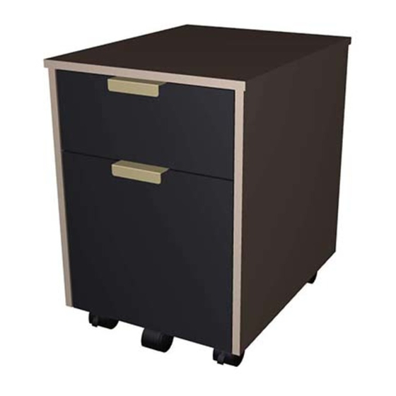
Devon File
Model # EC-DEDF
ADULT ASSEMBLY REQUIRED DUE TO THE PRESENCE OF SMALL PARTS, SHARP
POINTS, SHARP EDGES AS RECEIVED
If you have any questions regarding assembly or if parts are missing, DO NOT return this item to the
store where it was purchased. Please call our toll-free customer service number and have your
instructions and parts list ready to provide the model name, part name or factory number:
1-866-942-5362
Pacific Standard Time: 8:30 a.m. - 4:30 p.m., Monday - Friday
Or visit our web site 24 hours a day, 7 days a week for product assistance at
www.whalenfurniture.com
Or e-mail your request to parts@whalenfurniture.com
LOT NUMBER:
DATE PURCHASED: /
/
THIS INSTRUCTION BOOKLET CONTAINS IMPORTANT SAFETY INFORMATION.
PLEASE READ AND KEEP FOR FUTURE REFERENCE.
Date 2021-11-24
Rev. 0001-A
Advertisement

Related Manuals for Whalen Devon File EC-DEDF


Summary of Contents for Whalen Devon File EC-DEDF
- Page 1 Devon File Model # EC-DEDF ADULT ASSEMBLY REQUIRED DUE TO THE PRESENCE OF SMALL PARTS, SHARP POINTS, SHARP EDGES AS RECEIVED If you have any questions regarding assembly or if parts are missing, DO NOT return this item to the store where it was purchased.
-
Page 2: Special Note
M A X I M U M R E C O M M E N D E D W E I G H T L O A D S MANUFACTURER: Whalen Furniture Manufacturing CATALOG: Devon File MODEL # EC-DEDF MAXIMUM LOAD 50 lb. (22.7 kg) MAXIMUM LOAD 15 lb. - Page 3 IMPORTANT Before you begin: Open, identify and count all parts prior to assembly. Lay out parts on a flat and non- abrasive surface. You will need the parts identified on page 4 and 5 of this instruction manual. NOTE: IT IS VERY IMPORTANT TO USE GLUE WITH DOWELS. EXCESS GLUE CAN BE WIPED OFF WITH DAMP CLOTH.
- Page 4 Parts and Hardware List Please read completely through the instructions and verify that all listed parts and hardware are present before beginning assembly. A- Top Panel (Qty. 1) B- Left Side Panel (Qty. 1) C- Right Side Panel (Qty. 1) D- Back Panel (Qty.
- Page 5 Parts and Hardware List Please read completely through the instructions and verify that all listed parts and hardware are present before beginning assembly. S- Caster Support (Qty. 1) (Qty. 2) (Qty. 4) Guide Rail Guide Block (Qty. 2) W- Locking Caster (Qty. 2) X- Swivel Caster (Qty.
- Page 6 Utility Drawer Assembling 1. Unpack the unit and confirm that you have all the hardware and required parts. Assemble the unit on a carpeted floor or the empty carton to avoid any scratch. 2. Securely screw the Cam Bolts (3) into the designated small holes on the Utility Drawer Front (H) using a Phillips screwdriver.
- Page 7 Utility Drawer Assembling 4. Attach and align the Drawer Side Panels (J and K) to the Drawer Front (H) by engaging 4 Small Cam Locks (1) (Refer to page 3 on Cam Lock system operation supplement). 5. Slide the Drawer Bottom Panel (L) all the way into the grooves.
- Page 8 Utility Drawer Assembling 6. Fasten the Drawer Back Panel (I) to the Drawer Side Panels (J and K) with four 38 mm Screws (6). Make sure that Drawer Bottom Panel (L) fits securely into the groove of the Drawer Back Panel (I). 7.
- Page 9 File Drawer Assembling 8. Securely screw the Cam Bolts (3) into the designated small holes on the File Drawer Front (M) using a Phillips screwdriver. 9. Glue the M6 x 30 mm Wood Dowels (4) into the inner holes of File Drawer Side Panels (O and P).
- Page 10 File Drawer Assembling 10. Using the pilot holes as a guide. Align and attach the Caster Support (S) to the bottom side of the Drawer Bottom Support (R) with two 38 mm Screws (6), as shown. 11. Fasten one Swivel Caster (X) onto the Caster Support (S) with four 15 mm Pan Head Screws (8), using the pilot holes as a guide.
- Page 11 File Drawer Assembling 12. Align and attach the Drawer Bottom Support (R) to the Drawer Front (M) by engaging 2 Small Cam Lock (1) as shown. 13. Attach and align the Drawer Side Panels (O and P) to the Drawer Front (M) by engaging 4 Small Cam Locks (1) (Refer to page 3 on Cam Lock system operation supplement).
- Page 12 File Drawer Assembling 14. Slide the Drawer Bottom Panel (Q) all the way into the grooves. 15. Fasten the Drawer Back Panel (N) to the Drawer Side Panels (O and P) and the Drawer Bottom Support (R) with six 38 mm Screws (6). Make sure that Drawer Bottom Panel (Q) fits securely into the groove of the Drawer Back Panel (N).
- Page 13 File Drawer Assembling 16. Turn the assembled drawer upright. Attach the Handle (10) to the pilot holes on the Drawer Front (M) with two 12 mm Flat Head Screws (7). 17. Position Guide Rails (T) onto the Drawer Side Panels (O and P) with the high side facing inward. 18.
- Page 14 Assembly Instructions 19. Securely screw the Cam Bolts (3) into the designated small holes on the Top Panel (A), Back Panel (D) and Side Panels (B and C) using a Phillips screwdriver. 20. Glue the M8 x 30 mm Wood Dowels (5) into the inner holes of Side Panels (B and C), Back Panel (D), and Stretchers (E, F and G).
- Page 15 Assembly Instructions 21. Align and attach the Bottom Back Stretcher (G) to the Back Panel (D) by engaging 2 Large Cam Locks (2). 22. Align and attach the Back Panel assembly to the Left Side Panel (B) by engaging 4 Large Cam Locks (2).
- Page 16 Assembly Instructions 23. Align and attach the Bottom Front Stretcher (F) to the Left Side Panel (B) by engaging 2 Large Cam Locks (2). 24. Align and attach the Middle Crossbar (E) to the Left Side Panel (B) by engaging 1 Large Cam Lock (2).
- Page 17 Assembly Instructions 25. Repeat the previous steps to attach the Right Side Panel (C) at the opposite end. 26. Attach the Top Panel (A) to the previous assembly by engaging 6 Large Cam Locks (2).
- Page 18 Assembly Instructions 27. Using the pilot holes as a guide, attach two Locking Casters (W) to the Bottom Front Stretcher (F) with four 15 mm Pan Head Screws (8) per caster. 28. Repeat last step to attach two Swivel Casters (X) to the Bottom Back Stretcher (G). 29.
- Page 19 Assembly Instructions 31. Insert the assembled drawers into frame. To insert the assembled drawers into your unit, extend the Ball Bearing Slide Tracks on the Side Panels (B and C) all the way forward (including ball bearing cart). Then, align the Slide Runners on the assembled drawers with the Slide Tracks and push the drawer carefully inside until it stops.
-
Page 20: Care And Maintenance
Should this product be defective in workmanship or materials or fail under normal use, we will repair or replace it for up to one (1) year from date of purchase. Every Whalen Furniture product is designed to meet your highest expectations. We guarantee that you will immediately see the value of our fine furniture. - Page 21 Document Devon Modèle n EC-DEDF ASSEMBLAGE PAR UN ADULTE REQUIS EN RAISON DES PETITES PIÈCES, DES BOUTS POINTUS ET DES BORDS TRANCHANTS Pour toute question sur le montage ou en cas de pièce manquante, NE PAS retourner cet article au point de vente.
- Page 22 P O I D S M A X I M A L R E C O M M A N D É FABRICANT : Whalen Furniture Manufacturing CATALOG : Document Devon Modèle n : EC-DEDF 22,7 kg (50 lb.) CHARGE MAXIMALE 6,8 kg (15 lb.)
- Page 23 IMPORTANT Final COLLE Avant de commencer : Ouvrir, identifier et compter toutes les pièces avant le montage. Étendre les pièces sur une surface plane et non abrasive. Les pièces identifiées en page 4 et 5 de ce manuel d’instructions sont requises. REMARQUE : IL EST TRÈS IMPORTANT D’UTILISER DE LA COLLE AVEC LES GOUJONS.
- Page 24 Liste des pièces et de la quincaillerie Lire toutes les instructions et s’assurer d’avoir toutes les pièces et la quincaillerie avant de commencer le montage. A- Panneau supérieur (Qté. 1) B- Panneau latéral gauche (Qté. 1) C- Panneau latéral droit (Qté. 1) D- Panneau arrière (Qté.
- Page 25 Liste des pièces et de la quincaillerie Lire toutes les instructions et s’assurer d’avoir toutes les pièces et la quincaillerie avant de commencer le montage. S- Support des roulettes (Qté. 1) T- Rail de guidage (Qté. 2) U- Bloc de guidage (Qté. 4) V- Etagère (Qté.
- Page 26 Assemblage du tiroir utilitaire 1. Déballez l'unité et assurez-vous que vous avez tout le matériel et les pièces nécessaires. Assemblez l'unité sur un sol moquette ou sur le carton vide pour éviter les rayures. 2. Vissez fermement les petites boulons à came (3) dans les petits trous prévus à cet effet sur le devant du tiroir (H) à...
- Page 27 Assemblage du tiroir utilitaire Les rainures sont alignées et tournées vers l'intérieur 4. Fixez et alignez les panneaux latéraux du tiroir (J et K) sur le devant du tiroir (H) en engageant 4 petits verrous à came (1) (reportez-vous à la page 3 du supplément de fonctionnement du système de verrouillage à...
- Page 28 Assemblage du tiroir utilitaire 6. Fixez le panneau arrière du tiroir (I) aux panneaux latéraux du tiroir (J et K) à l’aide de quatre vis de 38 mm (6). Assurez-vous que le panneau inférieur du tiroir (L) s’insère bien dans la rainure du panneau arrière du tiroir (I).
- Page 29 Assemblage du classeur 8. Vissez fermement les petites boulons à came (3) dans les petits trous prévus à cet effet sur le devant du classeur (M) à l'aide d'un tournevis cruciforme. 9. Collez les chevilles à bois M6 x 30 mm (4) dans les trous intérieurs des panneaux latéraux du classeur (O et P).
- Page 30 Assemblage du classeur Les trous fraisés sont dirigés vers le haut 10. Utilisation des trous pilotes comme guide. Alignez et fixez le support de roulette (S) sur le côté inférieur du support de tiroir inférieur (R) à l'aide de deux vis de 38 mm (6), comme indiqué. 11.
- Page 31 Assemblage du classeur La roulette est tournée vers le bas 12. Alignez et fixez le support inférieur du tiroir (R) au devant du tiroir (M) en engageant 2 petits verrous à came (1) comme indiqué. Les rainures sont alignées et tournées vers l'intérieur 13.
- Page 32 Assemblage du classeur 14. Faites glisser le panneau inférieur du tiroir (Q) à fond dans les rainures. 15. Fixez le panneau arrière du tiroir (N) aux panneaux latéraux du tiroir (O et P) et au support inférieur du tiroir (R) à l'aide de six vis de 38 mm (6). Assurez-vous que le panneau inférieur du tiroir (Q) s’insère bien dans la rainure du panneau arrière du tiroir (N).
- Page 33 Assemblage du classeur 16. Redressez le tiroir assemblé. Fixez la poignée (10) aux trous avants du tiroir (M) à l’aide de deux vis à tête plate de 12 mm (7). 17. Positionnez les rails de guidage (T) sur les panneaux latéraux du tiroir (O et P) avec le côté haut tourné...
-
Page 34: Instructions D'assemblage
Instructions d'assemblage 19. Vissez fermement les boulons à came (3) dans les petits trous prévus à cet effet sur le panneau supérieur (A), le panneau arrière (D) et les panneaux latéraux (B et C) à l'aide d'un tournevis cruciforme. 20. Collez les chevilles en bois M8 x 30 mm (5) dans les trous intérieurs des panneaux latéraux (B et C), du panneau arrière (D) et des cadres (E, F et G). - Page 35 Instructions d'assemblage Les serrures à came sont tournées vers l'extérieur 21. Alignez et attachez le cadre inférieur arrière (G) au panneau arrière (D) en engageant 2 grandes serrures à came (2). 22. Alignez et assemblez le panneau arrière au panneau latéral gauche (B) en engageant 4 grands verrous à...
- Page 36 Instructions d'assemblage La découpe est tournée vers l'avant Les serrures à came sont tournées vers l'extérieur 23. Alignez et attachez le cadre avant inférieur (F) au panneau latéral gauche (B) en engageant 2 grands verrous à came (2). La serrure à came est tournée vers le bas 24.
- Page 37 Instructions d'assemblage 25. Répétez les étapes précédentes pour fixer le panneau latéral droit (C) à l’autre extrémité. 26. Fixez le panneau supérieur (A) à l’assemblage précédent en engageant 6 grands verrous à came (2).
- Page 38 Instructions d'assemblage Verrouillage des roulettes 27. En utilisant les trous de guidage comme guide, fixez deux roulettes de verrouillage (W) au cadre avant inférieur (F) à l’aide de quatre vis à tête cylindrique bombée de 15 mm (8) par roulette. 28.
- Page 39 Instructions d'assemblage Chariot à roulement à billes AVANT Chariot à roulement à billes AVANT Installation du tiroir 31. Insérez les tiroirs assemblés dans le cadre. Pour insérer les tiroirs assemblés dans votre unité, déployez les rails de glissière à roulement à billes sur les panneaux latéraux (B et C) au maximum (y compris le chariot à...
-
Page 40: Soin Et Entretien
Merci de votre achat! GARANTIE DE QUALITÉ Nous sommes assurés que vous serez ravi de votre achat d'un meuble de Whalen Furniture. Si la fabrication ou les matériaux de ce produit s'avéraient défectueux suite à une utilisation normale, nous le réparerons ou le remplacerons jusqu'à concurrence d'un (1) an après la date d'achat. Chaque produit de Whalen Furniture est conçu pour répondre aux normes les plus strictes. - Page 41 Archivero Devon Modelo # EC-DEDF ENSAMBLE POR ADULTO REQUERIDO POR LA PRESENCIA DE PARTES PEQUEÑAS, PUNTOS FILOSOS, Y BORDES FILOSOS Si tienen alguna pregunta acerca del ensamble o si alguna parte está faltante, no retorne esté producto a la tienda donde lo compró. Por favor llame a nuestro departamento de ayuda al cliente teniendo su instructivo y lista de partes para proveer el modelo, nombre de parte o el número de fábrica: 1-866-942-5362 Hora Estándar del Pacífico: 8:30 a.m.
- Page 42 PESOS MÁXIMOS RECOMENDADOS FABRICANTE: Whalen Furniture Manufacturing CATALOGO: Archivero Devon MODELO # EC-DEDF CARGA MÁXIMA 50 lb. (22.7 kg) CARGA MÁXIMA 15 lb. (6.8 kg) CARGA MÁXIMA 30 lb. (13.6 kg) ESTA UNIDAD DEBE UTILIZARSE CON LOS PESOS MÁXIMOS INDICADOS. SI SE EXEDE EL PESO MÁXIMO, PODRIA RESULTAR EN UNA INESTABILIDAD DE LA UNIDAD CAUSANDO POSIBLES LESIONES.
- Page 43 IMPORTANTE Antes de comenzar: Abra, identifique y cuente todas las partes antes del ensamble. Coloque los componentes en una superficie plana y no abrasiva. Usted necesitará las partes identificadas en la página 4 y 5 de este manual de instrucciones. NOTA: Es muy importante utilizar pegamento con los pernos.
- Page 44 Lista de partes y material de ferretería Por favor lea completamente las instrucciones y verifique que estén todas las partes antes de iniciar el ensamblado. A- Panel superior (Cant. 1) B- Panel izquierdo (Cant. 1) C- Panel derecho (Cant. 1) D- Panel posterior (Cant.
- Page 45 Lista de partes y material de ferretería Por favor lea completamente las instrucciones y verifique que estén todas las partes antes de iniciar el ensamblado. S- Soporte de rueda (Cant. 1) (Cant. 2) (Cant. 4) Riel guía Bloque guía V- Placa para archivero (Cant. 2) W- Rueda de bloqueo (Cant.
- Page 46 Ensamble del cajón 1. Desempacar la unidad y confirmar que se tiene todo el material de ferretería y partes requeridas. Ensamblar la unidad en un piso alfombrado o en el cartón vacío para evitar rasguños. 2. Atornillar los pernos de fijación pequeños (3) en los agujeros chicos designados en el frente del cajón (H) usando el desarmador estrella.
- Page 47 Ensamble del cajón 4. Adjuntar y alinear los paneles laterales del cajón (J y K) al frente del cajón (H) empleando 4 tuercas de fijación pequeñas (1) (Consulte la página 3 del sistema de tuerca de fijación). 5. Deslizar el panel inferior del cajón (L) todo el camino hacia las ranuras.
- Page 48 Ensamble del cajón 6. Sujetar el panel posterior del cajón (I) a los paneles laterales del cajón (J y K) con 4 pernos de 38 mm (6). Asegurar que el panel inferior del cajón (L) encaje en la ranura del panel posterior del cajón (I). 7.
- Page 49 Ensamble del cajón de archivero 8. Atornillar los pernos de fijación pequeños (3) en los agujeros chicos designados en el frente del cajón de archivero (M) usando el desarmador estrella. 9. Pegar la clavija de madera de M6 x 30 mm (4) en los agujeros interiores de los paneles laterales del cajón de archivero (O y P).
- Page 50 Ensamble del cajón de archivero 10. Usando los agujeros pilotos como guía, alinear y adjuntar el soporte de rueda (S) a la parte inferior del soporte inferior del cajón (R) con 2 pernos de 38 mm (6), como se muestra. 11.
- Page 51 Ensamble del cajón de archivero 12. Alinear y adjuntar el soporte inferior del cajón (R) al frente del cajón (M) empleando 2 tuercas de fijación pequeñas (1) como se muestra. 13. Adjuntar y alinear los paneles laterales del cajón (O y P) al frente del cajón (M) empleando 4 tuercas de fijación pequeñas (1) (Consulte la página 3 del sistema de tuerca de fijación).
- Page 52 Ensamble del cajón de archivero 14. Deslizar el panel inferior del cajón (Q) todo el camino hacia las ranuras. 15. Sujetar el panel posterior del cajón (N) a los paneles laterales del cajón (O y P) y el soporte inferior del cajón (R) con 6 pernos de 38 mm (6).
- Page 53 Ensamble del cajón de archivero 16. Voltear el ensamble del cajón en posición vertical. Adjuntar la manija (10) a los agujeros pilotos en el frente del cajón (M) con 2 pernos de cabeza plana de 12 mm (7). 17. Posicionar los rieles guía (T) sobre los paneles laterales del cajón (O y P) con el borde alto apuntado hacia adentro.
- Page 54 Instructivo de ensamble 19. Atornillar los pernos de fijación (3) en los agujeros chicos designados en el panel superior (A), en el panel posterior (D) y en los paneles laterales (B y C) usando el desarmador estrella. 20. Pegar las clavijas de madera de M8 x 30 mm (5) en los agujeros internos de los paneles laterales (B y C), el panel posterior (D), y de los soportes (E, F y G).
- Page 55 Instructivo de ensamble 21. Alinear y adjuntar el soporte inferior posterior (G) al panel posterior (D) empleando 2 tuercas de fijación grandes (2). 22. Alinear y adjuntar el ensamble del panel posterior al panel izquierdo (B) empleando 4 tuercas de fijación grandes (2).
- Page 56 Instructivo de ensamble 23. Alinear y adjuntar el soporte inferior frontal (F) al panel izquierdo (B) empleando 2 tuercas de fijación grandes (2). 24. Alinear y adjuntar el soporte medio (E) al panel izquierdo (B) empleando una tuerca de fijación grandes (2).
- Page 57 Instructivo de ensamble 25. Repetir los pasos previos para adjuntar el panel derecho (C) al lado opuesto. 26. Adjuntar el panel superior (A) al ensamble previo empleando 6 tuercas de fijación grandes (2).
- Page 58 Instructivo de ensamble 27. Usando los agujeros pilotos como guía, adjuntar 2 ruedas de bloqueo (W) al soporte inferior frontal (F) con 4 pernos de cabeza de arandela de 15 mm (8) por rueda. 28. Repetir el paso previo para adjuntar 2 ruedas giratorias (X) al soporte inferior posterior (G). 29.
- Page 59 Instructivo de ensamble 31. Insertar los cajones ensamblados en el marco. Para insertar los cajones ensamblados en la unidad, extender los carriles de la corredera de baleros en los paneles laterales (B y C) todo el camino hacia enfrente (incluyendo el carrito de baleros). Luego alinear los complementos de corredera en el cajón ensamblado con los carriles de corredera y empujar el cajón hacia adentro hasta que tope.
-
Page 60: Mantenimiento Y Cuidados
Si esté producto tiene algun defecto de ensamble o material, o si tiene alguna falla en uso normal, nosotros lo repararemos o lo re-emplazaremos hasta por un año a partir de la fecha de compra. Todo producto de Whalen Furniture es diseñado para alcanzar sus espectativas más altas. Nosotros le garantizamos que inmediatamente podrá...
Need help?
Do you have a question about the Devon File EC-DEDF and is the answer not in the manual?
Questions and answers