Advertisement
Table of Contents
- 1 Maximum Recommended Weight Loads
- 2 General Information, Tips and Tricks
- 3 Parts List
- 4 Hardware List
- 5 TV Mounting Kit
- 6 Assembly Instructions
- 7 Mounting Monitor Bracket to a Television with a Flat Back
- 8 Mounting Monitor Bracket to a Television with a Curved / Recess Back
- 9 Care and Maintenance
- 10 Quality Guarantee
- 11 Parts View and List
- Download this manual
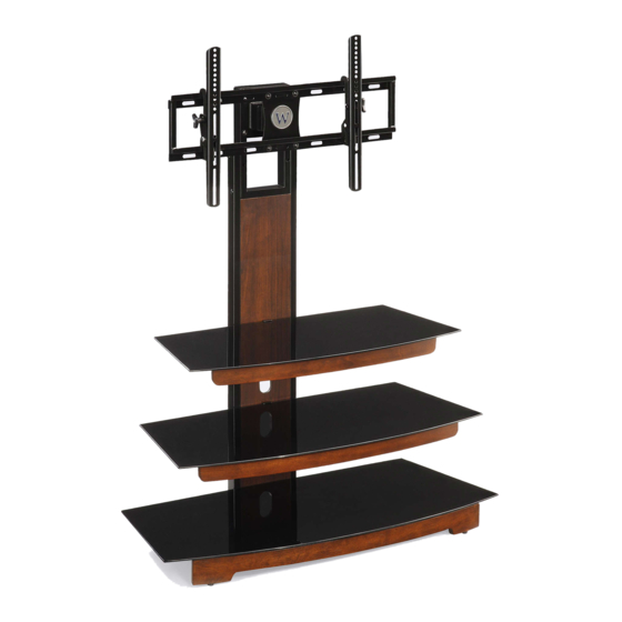
Flat Panel Console (PRO-9)
ADULT ASSEMBLY REQUIRED
If you have any questions regarding assembly or if you are missing parts, DO NOT return this item
to the store where it was purchased. Please call our toll-free customer service number and have
your instructions and parts list ready to provide the model name, part name or factory number:
1-866-942-5362
ONLINE: www.whalenstyle.com
THIS INSTRUCTION BOOKLET CONTAINS IMPORTANT SAFETY INFORMATION.
PLEASE READ AND KEEP FOR FUTURE REFERENCE.
Whalen Furniture Mfg. Inc.
8:30 a.m. - 4:30 p.m. PST, Monday - Friday
Video Instruction Guides
Go to http://whalen.showuhow.com to view step-by-step instructional
videos for assembling and installing your product. Enter the following
product number on the ShowUhow homepage.
PRO-9
LOT NUMBER:
DATE PURCHASED:
EMAIL: parts@whalenfurniture.com
Page 1
/
/
Factory No. 33- 10944
Advertisement
Table of Contents

Subscribe to Our Youtube Channel
Related Manuals for Whalen PRO-9


Summary of Contents for Whalen PRO-9
- Page 1 8:30 a.m. - 4:30 p.m. PST, Monday - Friday EMAIL: parts@whalenfurniture.com ONLINE: www.whalenstyle.com Video Instruction Guides Go to http://whalen.showuhow.com to view step-by-step instructional videos for assembling and installing your product. Enter the following product number on the ShowUhow homepage. PRO-9 THIS INSTRUCTION BOOKLET CONTAINS IMPORTANT SAFETY INFORMATION.
- Page 2 M A X I M U M R E C O M M E N D E D W E I G H T L O A D S MANUFACTURER: Whalen Furniture CATALOG: Flat Panel Console (PRO-9) DATE OF MANUFACTURE: April, 2011 MADE IN CHINA FITS UP TO MOST 47”...
- Page 3 Model # PRO-9 Parts List Please read completely through the instructions and verify that all parts listed are present before beginning assembly. A- Left Side Frame (1) B- Right Side Frame (1) C- Back Panel (1) D - Back Top Frame (1)
- Page 4 Model # PRO-9 Hardware List (2) 3/4” Bolt (3) 1-1/2” Bolt (1) Suction Cup (19+1 extra) (8+1 extra) (16+1 extra) (4) 2-1/4” Bolt (5) Hex Nut (6) Lock Washer (7) Flat Washer (8+1 extra) (8+1 extra) (32+1 extra) (36+1 extra)
- Page 5 Model # PRO-9 Assembly Instructions Note: Please do not fully tighten all bolts until you finish assembling all parts. Once assembled, go back and fully tighten all bolts. This will make it easier during assembly of unit. 1. Attach Back Top Frame (D) and Back Bottom Stretcher (E) between Left and Right Side Frame (A &...
- Page 6 Model # PRO-9 Assembly Instructions 2. Pick up Back Panel (C) and fit it between the front of Left and Right Side Frames (A & B). Insert and screw four #3 x 9 mm Screws (8) through the corner brackets to secure the Back Panel in place.
- Page 7 Model # PRO-9 Assembly Instructions 3. Lay down the unit on a level and protective surface as shown in detail #3. 4. Attach Bottom Brace (J) and Bottom Stringer (K) to the bottom rail of Left & Right Side Frame (A & B) with four 2-1/4” Bolts (4) and Washers (6 & 7) as shown in detail #3.
- Page 8 Model # PRO-9 Assembly Instructions 6. Attach Middle Crossbar (H) and Middle Stringer (I) to the middle rail of Left & Right Side Frame (A & B) using 1-1/2” Bolts (3) with Washers (6 & 7) through the pre-drilled holes on middle rails into place.
- Page 9 Model # PRO-9 Assembly Instructions 8. Adjust the Large Floor Levelers (10) installed and the small floor levelers pre-attached at the bottom of Bottom Stringer (K) to level the unit as shown in detail #5. Hardware provided Tools required Floor Levelers...
- Page 10 Model # PRO-9 Assembly Instructions 9. Attach Swiveling Bracket (O) to the top of Back Top Frame (D) with the pivoting bolt head up, using four 2-1/4” Bolts (4) with Washers (6 & 7) through the bracket holes and Back Top Frame and then secure with Hex Nuts (5).
- Page 11 Model # PRO-9 Assembly Instructions 10. Orient XYZ Mounting Frame (P) and attach to the Swiveling Bracket (O) using four 3/4” Bolts (2) with Washers and then secure with Hex Nuts (5). Make sure the slots on the Mounting Frame bottom. Securely tighten with Open Wrench and Allen Wrench provided. See detail #7.
- Page 12 Model # PRO-9 Mounting Monitor Bracket to a television with a flat back Note: For televisions with a curved back or recessed back proceed directly to step #13. 11. Determine the correct diameter of the bolt your TV requires by hand threading them into the threaded inserts on the back of the TV.
- Page 13 Model # PRO-9 Mounting Monitor Bracket to a television with a curved / recess back 13. Determine the correct diameter of the bolt your TV requires by hand threading them into the threaded insert on the back of the TV. If you encounter any resistance, stop immediately. If you are unable to find the correct bolt consult a local hardware store.
- Page 14 Model # PRO-9 Assembly Instructions 15. Once the Monitor Brackets (QL/QR) are attached onto the back of television, ask for assistance to lift the television up to attach the Monitor Brackets onto the XYZ Mounting Frame (P). Set the hooks on Monitor Brackets over the Mounting Frame then lower them onto the bars of Mounting Frame.
- Page 15 Model # PRO-9 Assembly Instructions 17. The Monitor Brackets (QL/QR) can tilt up to 11˚ downward and 5˚ upward, depending on your optimum viewing position. Have your assistant hold the TV steady before you start to adjust the tilt. Simply reach behind the TV and turn the both Tilt Adjustment Knobs with enclosed 3/16”...
- Page 16 Model # PRO-9 Assembly Instructions 18. Attach 2 Cable Controls (R) onto the backside of assembled unit with the 3/4” Bolts (2). Tighten the bolts with M4 Allen Wrench provided. See detail #12. 19. The Cable Controls (R) enable you to shorten, separate and route cables and cords. Using...
- Page 17 Model # PRO-9 Assembly Instructions 20. Put Suction Cups (1) firmly into the top holes on Crossbars & Stringers (F, G, H, I, J & K) as shown in detail #13. 21. Set Top Glass (L) & Glass Shelves (M & N) in place starting with Bottom Glass Shelf (N) as shown in detail #13.
- Page 18 Model # PRO-9 Assembly Instructions 22. Carefully move the console and position in your desired location against the wall. Now follow the instructions printed on the plastic bag containing Tipping Restraint Hardware to mount the Tipping Restraint Hardware Kit to the console and wall. As shown in detail #14.
- Page 19 Should this product be defective in workmanship or materials or fail under normal use, we will repair or replace it for up to one (1) year from the date of purchase. Every Whalen Furniture product is designed to meet your highest expectations. We guarantee that you will immediately see the value of our fine furniture.
Need help?
Do you have a question about the PRO-9 and is the answer not in the manual?
Questions and answers