Table of Contents

Related Manuals for Inficon Fab UL6000 Fab


Summary of Contents for Inficon Fab UL6000 Fab
- Page 1 Translation of the original operating instructions UL6000 Fab™ UL6000 Fab PLUS™ ™ Helium Leak Detector with ULTRATEST Sensor Technology Catalog No. 550-520, 550-530 From software version 1.62 (Operating unit) iinc75en1-02-(2207)
- Page 2 INFICON GmbH Bonner Strasse 498 50968 Cologne, Germany...
-
Page 3: Table Of Contents
INFICON Table of contents Table of contents 1 About this manual ............................ 8 1.1 Target groups............................ 8 1.2 Warnings .............................. 8 1.3 Definition of terms ............................ 8 2 Safety................................ 11 2.1 Intended use ............................ 11 2.2 Duties of the operator.......................... 13 2.3 Owner requirements.......................... - Page 4 Table of contents INFICON 5 Installation .............................. 39 5.1 Setup.............................. 39 5.2 Connect the supplied accessories ...................... 43 5.3 Fastening bracket for sniffer line SL3000 (accessory, optional) ............ 47 5.4 Connect recipient/test object to inlet flange ................... 47 5.5 Connecting to the power supply system .................... 48 5.6 Checking the operation of the device.....................
- Page 5 INFICON Table of contents 6.3.3 Setting setpoints ......................... 65 6.3.4 Activate vacuum ranges...................... 66 6.3.5 Influence the speed of the backing pump ................... 66 6.3.6 Switch TMP2 mode on or off....................... 66 6.3.7 HYDRO•S ........................... 66 6.3.7.1 Set HYDRO•S........................ 67 6.3.7.2...
- Page 6 Table of contents INFICON 6.8.6 Call the energy data information .................... 86 6.8.7 Call information on the HYDRO•S .................... 86 6.8.8 Call information on the SL3000 Sniffer line................. 87 6.9 Log ................................. 87 6.9.1 Call the error and warning log..................... 87 6.9.2 Call calibration log........................
- Page 7 INFICON Table of contents 9 Decommissioning ............................ 124 9.1 Disposing of the device ........................ 124 9.2 Returning the device for maintenance, repair or disposal.............. 124 10 Accessories and interfaces........................ 126 10.1 Accessories and spare parts........................ 126 10.2 I/O module............................ 130 10.2.1 Create a connection between the device and the I/O module ..........
-
Page 8: About This Manual
1 | About this manual INFICON 1 About this manual This document applies to the software version stated on the title page. Product names may occur in the document, which are added for identification purposes only and belong to the respective owner of the rights. - Page 9 INFICON About this manual | 1 Automatic tuning / mass setting This function adjusts the mass spectrometer so that a maximum leak rate indicator is achieved. In order to detect a maximum ion current with the ion detector, the control computer adjusts the voltage for accelerating the ions within the selected mass range accordingly.
- Page 10 1 | About this manual INFICON MASSIVE After selecting the vacuum range "MASSIVE" gross leaks can now be measured from atmospheric pressure. ULTRA ULTRA designates the connection to the turbo molecular pump for the measurement range with the highest sensitivity at low inlet pressures.
-
Page 11: Safety
• Exceeding permissible environmental conditions for test leaks • Use in radioactive areas • Modification of the device with additional attachments that change the stability. INFICON accessories are excluded. • Use of accessories or spare parts, which are not included in this instruction manual •... - Page 12 2 | Safety INFICON • Use of the optionally available bottle holder as a foothold • Connecting non-vacuum-resistant workpieces or test objects without splinter protection • Pumping out gases containing halogens such as fluorine or chlorine in high concentration or over a long period of time. Use with refrigerants or SF6.
-
Page 13: Duties Of The Operator
INFICON Safety | 2 2.2 Duties of the operator • Read, observe, and follow the information in this manual and in the work instructions provided by the owner. This concerns in particular the safety and warning instructions. • Always follow the complete operating instructions for all work. - Page 14 2 | Safety INFICON • As a wearer of such devices, keep at least 10 cm distance between the speaker magnet and the implant. • Furthermore, take into account distances specified by the manufacturer of the implant. Dangers from electric There is a danger to life from the contact of conductive parts inside the device.
-
Page 15: Scope Of Delivery, Transport, Storage
INFICON Scope of delivery, transport, storage | 3 3 Scope of delivery, transport, storage Scope of delivery Item Quantity UL6000 Fab or UL6000 Fab PLUS Mains connection cable (country-specific) Exhaust hose adapter ISO-KF flange DN25 Power cable strain relief (Pipe and bracket clamp) - Page 16 3 | Scope of delivery, transport, storage INFICON WARNING Risk of injury due to improper transport of a gas cylinder on the mobile leak detector ► When mounting the bottle holder on the leak detector, follow the sequence of action steps as described in the separate mounting instructions.
- Page 17 INFICON Scope of delivery, transport, storage | 3 CAUTION Risk of injury due to limited parking brakes Without properly functioning parking brakes, unintentional movements of the device and injuries may occur. ► To ensure proper functioning of the parking brakes, remove the adhesive strips from the wheels.
-
Page 18: Description
4 | Description INFICON 4 Description 4.1 Function The device is a leak detector for detecting and measuring leaks in test objects. The device is suitable for leak detection using the vacuum method and the sniffer method. It uses the ULTRATEST sensor technology. -
Page 19: Operation Mode "Sniffing
INFICON Description | 4 4.2.2 Operation mode "Sniffing" To scan test objects under overpressure with a sniffer probe, you can connect the SL200 sniffer line or the SL3000 sniffer line. SL200 The vacuum connection of the sniffer line SL200 is connected to the upper side of the device on the inlet flange. -
Page 20: Design Of Device
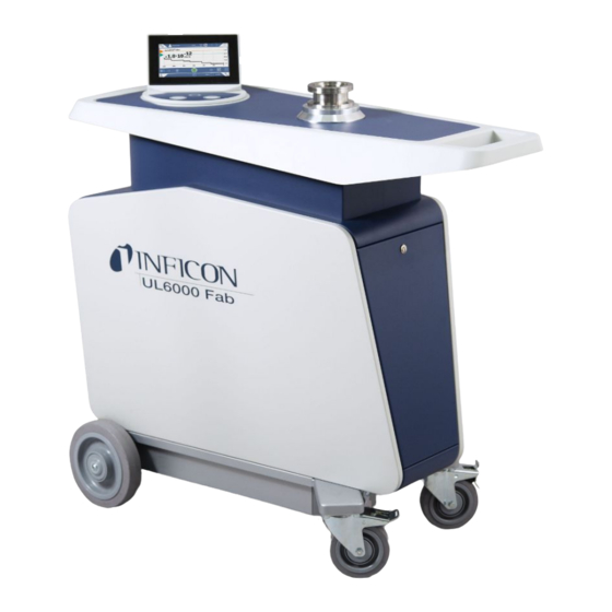
4 | Description INFICON 4.3 Design of device 4.3.1 Overall device Fig. 1: Front view 20 / 152 UL6000-Fab,-PLUS-Operating-instructions-iinc75en1-02-(2207) - Page 21 INFICON Description | 4 Fig. 2: Front view with open flap. UL6000-Fab,-PLUS-Operating-instructions-iinc75en1-02-(2207) 21 / 152...
- Page 22 4 | Description INFICON Fig. 3: Back view. The picture shows standard accessories and optional accessories. 22 / 152 UL6000-Fab,-PLUS-Operating-instructions-iinc75en1-02-(2207)
-
Page 23: Control Unit
INFICON Description | 4 4.3.2 Control unit Fig. 4: Control unit - front view The control unit consists of a touchscreen and a control panel with the buttons START, Stop and ZERO (background suppression) on the housing. Also see "Design of touchscreen [} 27] " and "START button [} 24]". -
Page 24: Start Button
4 | Description INFICON 1 HDMI interface • For connection to the HDMI interface of a touch monitor, maximum cable length 3 m. See also "Use external monitor [} 91]". 2 / 3 USB 2.0 Interfaces • For connecting the USB cable of a touch monitor, maximum cable length 3 m. -
Page 25: Zero Button
INFICON Description | 4 • Using the Stop button on the control panel you can do more than just stopping the measurements but also perform ventilation. Function Touchscreen Control panel Stop Stop button Vent Press the Stop button again and keep it pressed for approx. -
Page 26: Meaning Of The Button Leds
4 | Description INFICON 4.3.2.4 Meaning of the button LEDs START button LED STOP button LED Meaning Flashing red No connection to the control unit Pulsing blue Pulsing blue Run-up Green Standby vented (Vent valve open) Blue green Standby pumped out (Vent valve... -
Page 27: Design Of Touchscreen
INFICON Description | 4 Status LED Meaning Green Measure Yellow Measuring with warning not acknowledged Error 4.3.2.6 Design of touchscreen The display is a touchscreen. The touchscreen responds to being touched lightly. To correctly select the chosen function, avoid strong pressure. - Page 28 4 | Description INFICON • Orange: Warning is active (navigation button diagnosis) Settings Operation Information Diagnosis Table 1: Navigation buttons Function buttons The buttons can appear in three different colors: • Gray: Function is disabled • Light blue: Function can be activated •...
-
Page 29: Vacuum Connections
INFICON Description | 4 4.3.3 Vacuum connections 4.3.3.1 Inlet The inlet is located on the upper part of the device. It is a DN63 flange. If necessary, use a suitable reducer to connect the specimen to the inlet flange. An adapter DN63 ISO-K/DN40 ISO-KF is included in the scope of delivery. -
Page 30: Purge Gas Connection
4 | Description INFICON 4.3.3.3 Purge gas connection The connection for the purge gas is located on the lower side of the device, see "Connections for accessories and control signals [} 31]". This is a quick connection for hoses with an outside diameter of 8 mm. -
Page 31: Connections For Accessories And Control Signals
ACCESSORIES Electrical connection of the sniffer line SL200 Connection for bus module BM1000 or I/O module IO1000, maximum* cable length of INFICON data cable 30 m REMOTE CONTROL For connecting the remote control RC1000 via cable, maximum* length 28 m, or for direct connection of the radio transmitter via an adapter. -
Page 32: Markings On The Device
4 | Description INFICON 4.3.5 Markings on the device Device cannot be scrapped with the normal domestic waste. 4.4 Technical data Mechanical data UL6000 Fab, UL6000 Fab PLUS Dimensions (L × W × H) 1050 mm × 472 mm × 1040 mm Mass approx. 144 kg... - Page 33 INFICON Description | 4 Physical data UL6000 Fab, UL6000 Fab PLUS Minimum detectable leak rate, vacuum < 5 x 10 mbar l/s mode Response time, blind-flanged < 1 s Response time, 50 l volume ~ 1.4 s Maximum inlet pressure (Vacuum range...
-
Page 34: Factory Settings
4 | Description INFICON UL6000 Fab, UL6000 Fab PLUS Degree of contamination ***) **) Measuring condition for 40°C ambient temperature: Measuring mode ULTRA, gas load 35 sccm ***) According to DIN EN 61010-1: Only non-conductive contamination. Occasionally, temporary conductivity may occur due to condensation. - Page 35 INFICON Description | 4 Digital input pin 5 (IO1000) ZERO Digital input pin 6 (IO1000) Digital input pin 7 (IO1000) Clear Digital input pin 8 (IO1000) Purge Digital input pin 9 (IO1000) Start/Stop Digital input pin 10 (IO1000) No function...
- Page 36 4 | Description INFICON Lower pressure limit SL3000 capillary 80 mbar clogged Upper pressure limit SL3000 capillary 200 mbar broken Pressure limit MASSIVE -> GROSS 15.0 mbar Pressure limit GROSS -> FINE 2.0 mbar Pressure limit FINE -> ULTRA 0.3 mbar Evacuation time gross leak 600 s...
- Page 37 INFICON Description | 4 Air filter 2500 h Set user Name Supervisor 1111 Language English Diagram type set Line chart Line chart Scaling Logarithmic Decades Autoscale Lower diagram limit 1 × 10 Time axis 30 s Bar chart Scaling Logarithmic Decades Autoscale Lower diagram limit 1 ×...
- Page 38 4 | Description INFICON I•RISE unit Pa/min I•RISE permission User Leak rate setpoint I•RISE 6E-2 Pa/min @ 10 L 38 / 152 UL6000-Fab,-PLUS-Operating-instructions-iinc75en1-02-(2207)
-
Page 39: Installation
INFICON Installation | 5 5 Installation 5.1 Setup DANGER Danger due to electric shock The mains cable connected at both ends may be damaged or the wall socket may be torn out if the leak detector is moved and the mains cable is tensioned as a result. - Page 40 5 | Installation INFICON WARNING Fire hazard due to overload, short circuit and overheating ► Observe the permissible ambient conditions. ► Ensure sufficient ventilation, especially on the ventilation slots on the left and right of the device: There should be free space in the front, to the rear and sides of the unit of at least 10 cm.
- Page 41 INFICON Installation | 5 CAUTION Risk of injury due to uncontrolled rolling away ► To ensure proper functioning of the parking brakes, remove the adhesive strips from the wheels. ► To avoid uncontrolled rolling away, fix the device by locking the wheels with parking brake.
- Page 42 5 | Installation INFICON NOTICE Operating system can be hacked via USB or Ethernet The Linux operating system used in the leak detector is not updated automatically and can therefore contain security vulnerabilities. This vulnerability may be exploited through the Ethernet and USB interfaces of the leak detector to provide unauthorized access to the system.
-
Page 43: Connect The Supplied Accessories
INFICON Installation | 5 5.2 Connect the supplied accessories Install the “Hook for power line and sniffer line” Scope of delivery (amount): Hook (4x), screw M6 x 12 (4x), lock washer S6 (4x) Required tools (supplied): Wrench T30 (Torx) • In order to be able to fix the mains cable and, if necessary, a sniffer line on the device, mount the hooks on the device as shown. - Page 44 5 | Installation INFICON Fig. 8: Hook at the instrument or at the optional bottle holder. 44 / 152 UL6000-Fab,-PLUS-Operating-instructions-iinc75en1-02-(2207)
- Page 45 INFICON Installation | 5 Install the “Power line strain relief” Scope of delivery (amount): Strain relief (1x), screw M6 x 12 (1x), lock washer S6 (1x) Required tools (supplied): Wrench T30 (Torx) • To avoid the risk of tripping mount the “strain relief power supply” at the device.
- Page 46 5 | Installation INFICON Mounting the exhaust hose adapter on the device • To discharge gases through a DN25 exhaust hose, mount the KF flange DN25 exhaust hose adapter supplied in the exhaust port on the rear of the device.
-
Page 47: Fastening Bracket For Sniffer Line Sl3000 (Accessory, Optional)
INFICON Installation | 5 5.3 Fastening bracket for sniffer line SL3000 (accessory, optional) WARNING Risk of injury due to sniffer tip When stumbling, for example over lines, the sniffer tip can cause serious injuries, especially in eye contact. ► To avoid injury from the sniffer tip, align the sniffer tip in the bracket so that it points away from the operator. -
Page 48: Connecting To The Power Supply System
► If the cable is damaged, it must be replaced with an original "Hospital-Grade" spare part (INFICON p/n 200000587). ► Note that "Hospital-Grade" power cables are marked with the same lettering and green dot as the NEMA 5-15 power plug. -
Page 49: Checking The Operation Of The Device
INFICON Installation | 5 NOTICE Material damage due to excessive mains voltage The device can be damaged if the mains voltage is too high. ► Before connecting the device, check whether the mains voltage specification on the device matches the locally available mains voltage. - Page 50 5 | Installation INFICON In case you would like to suppress any possible existing background signals (helium background in the test object) press the ZERObutton. In order to reverse the background suppression press the ZERO button on the control panel for 2 - 3 seconds, see "ZERO button [} 25]”.
-
Page 51: Operation
INFICON Operation | 6 6 Operation 6.1 Switching on NOTICE Damage to the backing pump due to cold ambient temperature If the ambient temperature is below 10 °C, the device will show a warning on the display after switching on. It is possible to start up the device anyway by confirming this message. -
Page 52: Basic Settings
6 | Operation INFICON 6.2 Basic settings 6.2.1 Set language on the user interface You can set the language in the user settings, see "Select, modify, create user profile [} 53]". 6.2.2 Setting date, time and time zone ü Supervisor rights >... -
Page 53: Select, Modify, Create User Profile
INFICON Operation | 6 6.2.3.2 Select, modify, create user profile ü Operator or Supervisor rights > User accounts > Manage user accounts ð Existing users and associated groups are displayed in list form. You have the following possibilities: To create a new user profile, select at the bottom of the window. -
Page 54: Modify Personal Settings
6 | Operation INFICON Save 6.2.3.3 Modify Personal Settings As a user with limited rights (User) you can also modify your language or PIN. By this the associated user profile is correspondingly adapted. Access to the entire user profile is not necessary. -
Page 55: Presentation Of The Measurement Screen
INFICON Operation | 6 ü The requested user was already created. See "Select, modify, create user profile [} 53]". > User accounts > Manage Automatic Login In the “Manage Automatic Login” window, activate the option “Active”. Enter the name of the user in the "Name" field. Note the uppercase/lowercase. -
Page 56: Changing The Presentation Of The Bar Graph
6 | Operation INFICON In the field "Scaling" select between "Linear" and "Logarithmic". Select between the different viewable ”Decades”. To dynamically adjust the upper and lower limit on the leak rate, activate the option "Autoscale". In the field "Time axis" select the length of the time axis "30", "60", "90", "120"... -
Page 57: Changing The Presentation Of The Circle Graph
INFICON Operation | 6 6.2.6.3 Changing the presentation of the circle graph Fig. 12: Presentation of the circle chart ü Operator or Supervisor rights > Display > Circle chart If you want to fix the number of displayed decades in the circle chart, under "Decades“... -
Page 58: Change Units
6 | Operation INFICON Save 6.2.7 Change units For the vacuum operation mode you can select between "Torr·l/s", "atm·cc/s", "Pa·m s", and "mbar·l/s". After switching the operation mode "Sniffer" in addition to the modes mentioned above you can also select between the units "oz/yr", "g/a" and "ppm". -
Page 59: Change The Protection Settings
INFICON Operation | 6 ð You can listen to the set volume using the "Test" button. If necessary, change the minimum volume. ð The "Minimum volume" is the volume for the audible alarm which cannot be undershot. If you select a value greater than 0, the lowest volume level is shown on the measurement screen after pressing the volume icon. - Page 60 6 | Operation INFICON ð The device closes the inlet valve as soon as the measured leak rate exceeds the shut-down threshold. This will prevent an excess amount of helium from entering the mass spectrometer. Consequently, the leak detector is prevented from becoming contaminated by Helium.
-
Page 61: Set Maintenance Interval "Filter Sniffer Tip" Or "Air Filter
INFICON Operation | 6 6.2.10 Set maintenance interval "Filter sniffer tip" or "Air filter" To adjust the maintenance interval to the degree of contamination at the location of the device, you can choose between a default value or a self-selected maintenance interval. -
Page 62: Activating Or Deactivating Calibration Requests
6 | Operation INFICON 6.2.12 Activating or deactivating calibration requests If the option "calibration request” is not active (factory setting), you only get a calibration request in the following cases: • A SL3000 sniffer line with a new serial number has been connected. -
Page 63: Measure Internal Calibration Leak After Run-Up
INFICON Operation | 6 Save 6.2.14 Measure internal calibration leak after run-up After activating this option, the function "Measure internal calibration leak after run-up" is automatically executed after run-up. This can be used to check that the leak detector is functioning correctly. -
Page 64: Turn Notifications On Or Off
6 | Operation INFICON ð The icon and the icon for deletion are displayed. After pressing the icon , the list overview is displayed with the menu names from which you make your selection and save it by pressing 6.2.16 Turn notifications on or off ü... -
Page 65: Settings For The Measurements
INFICON Operation | 6 6.3 Settings for the measurements 6.3.1 Select operation mode ü Operator or Supervisor rights > Operation mode Select between "Vacuum", "Sniffer / SL200" and "Sniffer / SL3000". Save 6.3.2 Select gas DANGER Danger from a Hydrogen explosion Hydrogen can explode in combination with oxygen. -
Page 66: Activate Vacuum Ranges
6 | Operation INFICON Adjust. Save 6.3.4 Activate vacuum ranges Vacuum ranges You can activate the vacuum ranges MASSIVE, GROSS, FINE and ULTRA for your measurements. All 4 areas can be activated at the same time. If several areas are activated, they switch automatically depending on the inlet pressure p1. -
Page 67: Set Hydro•S
INFICON Operation | 6 6.3.7.1 Set HYDRO•S In addition to the basic setting described here, the availability of HYDRO•S depends on additional requirements, such as the selected operation mode and the operating state, see “Use HYDRO•S [} 67]”. ü Supervisor rights >... -
Page 68: Setting The Machine Factor
6 | Operation INFICON 6.3.8 Setting the machine factor If you are measuring in the operation mode "Vacuum" and using an external pump in parallel, the measured leak rate would be too small in comparison to the leak rate based on an internal calibration. -
Page 69: Set And Use The Function Zero
INFICON Operation | 6 The pressure limits refer to the pressure sensor "p1", the inlet pressure of the turbo molecular pump 1. See also "View vacuum diagram [} 92]". Using this function the factory settings for the switching points between the vacuum ranges MASSIVE, GROSS, FINE and ULTRA can be changed. - Page 70 6 | Operation INFICON A currently displayed leak is hidden through ZERO. By using the function ZERO not only is the background signal hidden, but also the representation of a current leak. ► If you want to prevent this, select the function ZERO only if not measuring a leak at the same time.
-
Page 71: Vent, Purge, Regenerate
INFICON Operation | 6 "Sniffing" operation When you press the ZERO button, the current leak rate value is set to the lower mode, setting display limit. "I•ZERO 2.0" or “ZERO“ 6.3.12 Vent, purge, regenerate Vent In measuring mode, you use this function to vent the inlet of the device and a test specimen connected to it after a measurement. -
Page 72: Change Leak Rate Filter
6 | Operation INFICON You can automatically purge the backing pump for 20 seconds when you change to "Standby". ü Operator or Supervisor rights > Setup > Measurement > Vacuum > Purge If necessary activate the option "Automatic purge". ð If you switch off the automatic purging, you can switch purging on or off in the... -
Page 73: Change Background Suppression
INFICON Operation | 6 6.3.14 Change background suppression The internal background suppression is preset. The measurement system of the leak detector contains a residual amount of helium and hydrogen even without connection to a test chamber. This creates an internal measurement signal component already before pressing the START button. -
Page 74: Determine The Background Of The Inlet Area
6 | Operation INFICON High background value If the actual background is higher than 1×10 mbar l/s, it can no longer be automatically deducted. The high background must be pumped down in this case. 6.3.14.1 Determine the background of the inlet area This function determines the value of the internal Helium background. -
Page 75: Calibrating
INFICON Operation | 6 Inlet pressure < Lower limit: Gas flow is too low through the caliper (blocked caliper). ü Supervisor rights > Setup > Measurement > Sniffing > Capillary surveillance ð You can change the following settings, to view the preset values see “Factory settings“. -
Page 76: External Calibration
6 | Operation INFICON 6.3.17.2 External calibration ü Operator or Supervisor rights Mount the calibration leak on the inlet of the device. > Setup > Measurement > Calibration leak Adjust the leak rate of the calibration leak used, see also “Set external calibration leak [} 68]”. -
Page 77: Measure
INFICON Operation | 6 6.4 Measure ü The inlet flange on the upper side of the device is prepared for the pending measurement. Your test specimen or the SL200 sniffer line is normally connected there. See also "Connect recipient/test object to inlet flange [} 47]". -
Page 78: Leak Detection With I•Rise (Device-Dependent)
Subsequently, a pressure rise in the recipient is usually measured in mbar/min or Torr/min. With INFICON's I•RISE solution, the pressure rise is measured in a volume inside the leak detector and thus outside the recipient. Compared to a conventional pressure rise measurement, it can be measured much faster and continuously. - Page 79 INFICON Operation | 6 ð The turbo molecular pump 2 can be switched on or off, see “Switch TMP2 mode on or off [} 66]“ (supervisor rights). ð When I•RISE measurement is possible, the color of the I•RISE icon changes from gray to blue on the measurement screen.
-
Page 80: Measuring Helium Ambient Concentration
6 | Operation INFICON ð By clicking on the unit or the volume display, you can go directly to the I•RISE settings. ð By clicking on the setpoint marker, you can go directly to the I•RISE setpoint setting. ð By clicking on the axis labels you can go directly to the settings for displaying the I•RISE diagram. -
Page 81: Measurement Data
INFICON Operation | 6 ü There are no long hoses connected to the "purge gas connection". There, the air enters the device whose helium concentration is measured. See also "Connections for accessories and control signals [} 31]". ü The device is in the "Standby" state. -
Page 82: Display Measurement Cycles
6 | Operation INFICON Under “Export format” select between "CSV en", "CSV de" and "JSON". ð Standard is "CSV en". For "CSV en", the column separator is a comma. For "CSV de", the column separator is a semicolon. "JSON" is a language-independent data format. -
Page 83: Export Measurement Data Via Network
INFICON Operation | 6 To export the displayed cycle, connect a USB flash drive (FAT32 formatted) to the leak detector and press 6.7.3 Export measurement data via network In addition to access to the graphical user interface, you also have the option of retrieving specific measurement data from your leak detector. -
Page 84: Measurement Data Database: Information
6 | Operation INFICON Returns measured values and metadata of the measurement cycle with ID 4 in the format “csv_en”. Example 2: http://ul3xxx.inficon.com:3000/md?dts=2018-11-05T23:00:00.000Z&dte= 2018-11-06T23:00:00.000Z&f=json&d=r Returns measured values between 2018-11-05T23:00:00.000Z und 2018-11-06T23:00:00.000Z in the “json” format. Parameter Name Description Options Example... -
Page 85: Information
INFICON Operation | 6 the database “Level“ “Oldest record“: Time stamp of the oldest measurement value “Newest record“: Time stamp of the newest measurement value See also 2 Resetting to factory settings [} 93] 6.8 Information 6.8.1 Call the latest information to the current measurement value ►... -
Page 86: Call Information On The Assemblies
6 | Operation INFICON ► > Device > Operating hours ► > Device > MSB 6.8.5 Call information on the assemblies Diverse measurement values and information to the following assemblies is shown: Preamplifier, ion source, turbo molecular pump (TMP), processor assembly MSB, backing pump and its frequency converter. -
Page 87: Call Information On The Sl3000 Sniffer Line
INFICON Operation | 6 6.8.8 Call information on the SL3000 Sniffer line ► > Sniffer line 6.9 Log 6.9.1 Call the error and warning log ► > Logs > Errors and warnings If there are more than 20 entries always the oldest entry is deleted. -
Page 88: Saving And Managing Sets Of Parameters
6 | Operation INFICON ► To modify parameters, press alternatively a subheading in the list. A separate setting window will be opened, where you can change and save. ð After changing a parameter setting in a separate window press to return to the list of parameters. -
Page 89: Exporting Or Importing Sets Of Parameters
INFICON Operation | 6 6.10.3 Exporting or importing sets of parameters You are able to transfer saved sets of parameters from the internal memory to an attached USB flash drive and to import the sets again. ü Supervisor rights > Parameter sets > Manage parameter sets... -
Page 90: Updating The Software Of The Basic Unit
6 | Operation INFICON NOTICE Loss of data due to disconnection ► Do not switch off the device and do not remove the USB flash drive while the software is being updated. ü Supervisor rights Copy the file into the main directory of a FAT32 formatted USB flash drive. -
Page 91: Update The Software In Expert Mode
INFICON Operation | 6 6.11.3 Update the software in expert mode ü Supervisor rights > Update > Update operating unit/basic unit > Operating unit expert update ð Software versions already available on the device are shown in a list. Highlight any of the software versions as required and proceed to step 5. -
Page 92: Switch Back To The Internal Monitor
6 | Operation INFICON Connect the HDMI cable and the USB cable of the touch monitor with the connector block of your leak detector, see also “Connections for accessories and control signals [} 31]“. For proper operation, make sure that the cable length does not exceed 3 m. -
Page 93: Resetting To Factory Settings
INFICON Operation | 6 Fig. 13: The most important components of the vacuum diagram in UL6000 devices 1 Turbo molecular pump 2 (Booster TMP) 6 Mass spectrometer 2 Inlet flange 7 Turbo molecular pump 1 3 p1 … p4: Pressure measuring points... -
Page 94: Logging Off From The Device
6 | Operation INFICON 6.15 Logging off from the device Press your name, which is displayed in the upper left corner of the display, or select > User accounts. ð The window "User accounts" opens. See also "Modify Personal Settings [} 54]". -
Page 95: Warning And Error Messages
INFICON Warning and error messages | 7 7 Warning and error messages During operation, the display shows information that helps you operate the device. Measurement values are displayed along with current device modes, operating instructions as well as warnings and error messages. The device is equipped with extensive self-diagnostic functions. -
Page 96: Warning And Error Messages Ul3000/Ul6000
7 | Warning and error messages INFICON 7.1 Warning and error messages UL3000/UL6000 Type Notification Possible sources of Remedy error W102 Timeout during The EEPROM on the • Contact customer service communication with VI-Board is defective or EEPROM on VI-Board... - Page 97 INFICON Warning and error messages | 7 Type Notification Possible sources of Remedy error W110 Real-time clock was reset! The real-time clock has • Enter the correct date and time Enter date and time not been set • Check that the message does not appear...
- Page 98 7 | Warning and error messages INFICON Type Notification Possible sources of Remedy error W125 I/O module no longer Connection to I/O • Check the connection to the I/O module connected module interrupted • Replace the connection cable to the I/O...
- Page 99 INFICON Warning and error messages | 7 Type Notification Possible sources of Remedy error W153 Operating unit software A more up-to-date • Contact the customer service for the version is obsolete operating unit software latest operating unit software is available. For...
- Page 100 7 | Warning and error messages INFICON Type Notification Possible sources of Remedy error W208 24V fan supply voltage out Malfunction of a fan • Contact customer service of range Short circuit or • Contact customer service overload in the 24V fan...
- Page 101 INFICON Warning and error messages | 7 Type Notification Possible sources of Remedy error W222 Internal voltage 24V_IO The module connected • Use another module, if possible voltage out of range to LD connector is defective The cable connected to •...
- Page 102 7 | Warning and error messages INFICON Type Notification Possible sources of Remedy error W254 Valve current is out of range One or more lowered • Contact customer service valves are not connected or defective VI-Board or MSB • Contact customer service...
- Page 103 INFICON Warning and error messages | 7 Type Notification Possible sources of Remedy error W311 Cathode 2 broken Cathode defective • Check that the other cathode has been switched on • Contact customer service Connection to cathode • Contact customer service...
- Page 104 7 | Warning and error messages INFICON Type Notification Possible sources of Remedy error W360 Preamplifier output signal Ion source defective • Contact customer service too low Mass spectrometer • Contact customer service contaminated W361 The offset voltage of the Preamplifier defective •...
- Page 105 INFICON Warning and error messages | 7 Type Notification Possible sources of Remedy error E410 TMP temperature too high The ambient • Turn off the device and let it cool down temperature is too high • Reduce the temperature in the...
- Page 106 7 | Warning and error messages INFICON Type Notification Possible sources of Remedy error E451 Temperature prewarning of The ambient • Reduce the temperature in the backing pump temperature is too high environment where the device is located Ambient temperature is •...
- Page 107 INFICON Warning and error messages | 7 Type Notification Possible sources of Remedy error E457 Fault in backing pump: The backing pump in • Make sure that you use the supplied Power failure the leak detector has a power cord faulty mains input •...
- Page 108 7 | Warning and error messages INFICON Type Notification Possible sources of Remedy error E463 Temperature error of The ambient • Reduce the temperature in the backing pump temperature is too high environment where the device is located Fan blocked or •...
- Page 109 INFICON Warning and error messages | 7 Type Notification Possible sources of Remedy error E504 Pressure sensor p3 not Pressure sensor not • Contact customer service connected connected or cable defective VI-Board or MSB • Contact customer service defective E505...
- Page 110 7 | Warning and error messages INFICON Type Notification Possible sources of Remedy error W541 Flow through capillary is Filter is dirty • Replace the sniffer tip filter much too low! Leaks may Sniffer tip or capillary • Remove the blocking of the sniffer tip...
- Page 111 INFICON Warning and error messages | 7 Type Notification Possible sources of Remedy error W618 I-BOOST leak rate dropped The 'I-BOOST time • Perform the procedure for determining the faster than expected (5 s constant' for the 'I-BOOST time constant' again...
- Page 112 7 | Warning and error messages INFICON Type Notification Possible sources of Remedy error W630 Calibration request Operation mode or • Perform a calibration mass has changed HYDRO•S has been • Perform a calibration switched on (if function available) Auto Leak Test is •...
- Page 113 INFICON Warning and error messages | 7 Type Notification Possible sources of Remedy error E709 MSB temperature is too low Ambient temperature is • Increase the temperature in the too low environment where the device is located Temperature sensor is •...
-
Page 114: Cleaning And Maintenance
8 | Cleaning and maintenance INFICON 8 Cleaning and maintenance All cleaning and maintenance work described here must be carried out without opening the device! DANGER Risk of death from electric shock There are high voltages inside the device. Touching parts where electrical voltage is present can result in death. -
Page 115: Replacement Of The Filter Mat On The Bottom Of The Device
INFICON Cleaning and maintenance | 8 Remove the used air filter from the plastic grid and insert a new one. Refit the plastic grid together with the new air filter. 8.3 Replacement of the filter mat on the bottom of... -
Page 116: Replacing The Sl200 Sniffer Line Filter
8 | Cleaning and maintenance INFICON Loosen the screws, which fix the filter mat on the metal sheet. Replace the filter mat. Secure the filter mat with the screws, insert the metal sheet and fix it with the knurled screw. - Page 117 INFICON Cleaning and maintenance | 8 3 Capillary filter (metal with gasket; 6 Gasket option) A blockage of the sniffer tip can have the following causes: Capillary filter blocked -> replace felt discs or capillary filter Sinter filter clogged -> check or replace sinter filter Capillary clogged in sniffer tip ->...
-
Page 118: Replacing The Sl3000 Sniffer Line Filter
8 | Cleaning and maintenance INFICON If you have activated the display of maintenance requests, set the maintenance interval to the desired new period. Also see "Activate or deactivate maintenance requests [} 61] " and "Set maintenance interval "Filter sniffer tip" or "Air filter" [} 61]". -
Page 119: Mounting Or Changing The Gas Cylinder
INFICON Cleaning and maintenance | 8 Push the metal grill and then the two new inserts into the filter from the front. Make sure that grill and inserts do not cant. Switch on the leak detector. Close the sniffer probe with your finger. With the water protection tip, you have to also cover the opening on the side. -
Page 120: Creating Screenshots
8 | Cleaning and maintenance INFICON WARNING Risk of injury due to improper mounting of a gas cylinder on the mobile leak detector ► When mounting the bottle holder on the leak detector, follow the sequence of action steps as described in the separate mounting instructions. - Page 121 INFICON Cleaning and maintenance | 8 You can send in your device to INFICON so it can be maintained or repaired. For further details see "Returning the device for maintenance, repair or disposal [} 124]”. UL6000-Fab,-PLUS-Operating-instructions-iinc75en1-02-(2207) 121 / 152...
-
Page 122: Maintenance Plan
• I Customer or higher level schedule legend • II Customer with instruction or higher level • III INFICON Service Technician • X Carry out maintenance as per operating hours or duration • X Maintenance after operating hours, not after duration •... - Page 123 INFICON Cleaning and maintenance | 8 To the Kashiyama NeoDry backing pump When pumping clean gases such as dry air and inert gases, the recommended schedule for preventive maintenance is 3 years. When pumping condensable gases such as water vapour and gas-mixed solvents as well as aggressive or corrosive gases, it may be necessary to reduce the maintenance interval to one year.
-
Page 124: Decommissioning
9 | Decommissioning INFICON 9 Decommissioning 9.1 Disposing of the device The device can either be disposed of by the operator or be sent to the manufacturer. The device consists of materials that can be recycled. This option should be exercised to prevent waste and also to protect the environment. - Page 125 INFICON Decommissioning | 9 UL6000-Fab,-PLUS-Operating-instructions-iinc75en1-02-(2207) 125 / 152...
-
Page 126: Accessories And Interfaces
10 | Accessories and interfaces INFICON 10 Accessories and interfaces 10.1 Accessories and spare parts The parts listed below can additionally be ordered: Bus module BM1000 PROFIBUS 560-315 BM1000 PROFINET IO 560-316 BM1000 DeviceNet 560-317 BM1000 EtherNet/IP 560-318 I/O module... - Page 127 INFICON Accessories and interfaces | 10 Further accessories for the SL3000 Felt For Capillary Filter SL3xx, 50 pc. 200001116 Capillary filter, metal(1 unit) 12217 Capillary Filter SL 300, set 5 pieces(Plastic capillary filter) 20003501 Intern Filter For SL3XX (5/PKG)(Sinter-filter with O-Ring)
- Page 128 10 | Accessories and interfaces INFICON Remote control RC1000C and RC1000WL With the RC1000C remote control you can operate the leak detector over a cable with a length of up to 28 m. With the wireless remote control RC1000WL, you can operate the leak detector at a distance of up to 100 m.
- Page 129 INFICON Accessories and interfaces | 10 Search for the wireless remote control from the leak detector If you have misplaced the RC1000WL wireless remote control, you can trigger from your leak detector acoustic signals of this remote control. > Setup > Accessories > RC1000 Select the setting “ON”...
-
Page 130: I/O Module
ü Supervisor rights Connect the INFICON I/O module with a data cable to the LD socket on the rear of the device, see "Connections for accessories and control signals [} 31]". > Setup > Accessories > Device selection Select the "IO module". - Page 131 INFICON Accessories and interfaces | 10 Pressure p1 / Pressure 1 ... 10 V; 0.5 V / decade; logarithmic 1 V = 1 x 10 mbar Leak rate mantissa 1 ... 10 V; linear; in the Useful only if the other analog output is assigned selected unit "Leak rate exponent".
-
Page 132: Configure Digital Inputs
10 | Accessories and interfaces INFICON Leak rate log. 0 ... 10 V; logarithmic; The upper limit (= 10 V) and the scale (V / decades) are set via the parameters "Exponent upper limit" and in the selected unit "Analog output scaling". -
Page 133: Configuring Digital Outputs
INFICON Accessories and interfaces | 10 ð The modes "Standard" or the mode "Inverse" are available for selection. To mode "Inverse": In the following table overview, the arrow pointing the transfer direction in the column "Transition" must be reversed. Save... - Page 134 10 | Accessories and interfaces INFICON Function State: Description Ready for operation closed: Emission switched on, calibration process inactive, no error open: Emission switched off or calibration process active or error Emission on closed: Emission switched on open: Emission switched off...
-
Page 135: Setting Up The I/O Module Protocol
INFICON Accessories and interfaces | 10 Function State: Description Setpoint 4 closed: Measured leak rate exceeds the setpoint 4 open: Measured leak rate undercuts the setpoint 4 Purge closed: Purge valve open open: Purge valve closed Vent closed: Internal vent valve open. -
Page 136: Bus Module
To establish the connection between the leak detector and the bus module, proceed as follows: Switch off the leak detector. Connect the INFICON bus module via a data cable to the LD socket of the device, see “Connections for accessories and control signals [} 31]“. Switch on the leak detector. -
Page 137: Network
INFICON Accessories and interfaces | 10 10.4 Network 10.4.1 Operate leak detector via web browser (LAN) NOTICE Operating system can be attacked via USB or Ethernet The Linux operating system used in the leak testing is not updated automatically and can therefore contain security gaps. -
Page 138: Setting The Lan Connection In The Pc Or Tablet
10 | Accessories and interfaces INFICON 10.4.1.2 Setting the LAN connection in the PC or Tablet LAN connection - quick start If you have performed the steps described here once, it is sufficient to enter the IP address for many devices in case of repetition. -
Page 139: Operate Leak Detector Via Web Browser (Wireless Lan)
INFICON Accessories and interfaces | 10 10.4.2 Operate leak detector via web browser (wireless LAN) NOTICE Operating system can be attacked via USB or Ethernet The Linux operating system used in the leak testing is not updated automatically and can therefore contain security gaps. This vulnerability may be exploited through the Ethernet and USB interfaces of the leak testing to provide unauthorized access to the system. -
Page 140: Setting The Wireless Lan Connection In The Pc Or Tablet
10 | Accessories and interfaces INFICON To set-up that the device supports the WLAN connection activate the option "Enable Wireless LAN". In the field “WiFi Name (SSID)” enter the desired network name and in the field “WiFi Network key” the desired Network key. -
Page 141: Allow Client Access
INFICON Accessories and interfaces | 10 10.4.2.3 Allow client access ü Supervisor rights > Setup > Network > Client access To allow the leak detector to be operated by PC or Tablet, activate the "Client Access" option. ð If the option "Client Access" is not activated, the leak detector cannot be operated via PC or Tablet. -
Page 142: Appendix
11 | Appendix INFICON 11 Appendix 11.1 Menu path 11.1.1 Diagnosis > Confirmed warnings > Errors and warnings > Measurement data > Data recording > Measurement data > Database information > Measurement data > Measurement data export > Measurement data > Measurement cycles >... - Page 143 INFICON Appendix | 11 > User accounts > Favorites > Operation mode > Setup > General > Notifications > Setup > General > Date and time > Setup > General > Settings of units > Setup > General > Reset >...
-
Page 144: Information
11 | Appendix INFICON > Setpoints 11.1.3 Information > Assemblies > Ion source > Assemblies > TMP > Assemblies > TMP2 > Assemblies > Backing pump > Assemblies > Preamplifier > Energy > Power > Energy > Voltage (1) > Energy > Voltage (2) >... -
Page 145: Ce Declaration Of Conformity
INFICON Appendix | 11 11.2 CE Declaration of Conformity UL6000-Fab,-PLUS-Operating-instructions-iinc75en1-02-(2207) 145 / 152... - Page 146 11 | Appendix INFICON 146 / 152 UL6000-Fab,-PLUS-Operating-instructions-iinc75en1-02-(2207)
-
Page 147: Rohs
INFICON Appendix | 11 11.3 RoHS UL6000-Fab,-PLUS-Operating-instructions-iinc75en1-02-(2207) 147 / 152... -
Page 148: Index
Index INFICON Index Evacuation time measurements 60 Exhaust 29, 46 Access controls 52 Activate additional function 91 Automated login Factory settings 34 Switch off 54 Function description 18 Switch on 54 HYDRO•S Background signal 10 Definition 18 Background suppression 9, 73 67... - Page 149 INFICON Index User interface update 89 Supervisor 52, 54 Operating options 62 Switch monitor 24, 91, 92 Operation Switch off 94 PC, Tablet 140 Switching on 51 Operation mode "Sniffing" 19, 65 Operation mode "Vacuum" 18, 65 Operator 52 Take a screenshot 120...
- Page 150 Index INFICON Factory setting 70 150 / 152 UL6000-Fab,-PLUS-Operating-instructions-iinc75en1-02-(2207)
Need help?
Do you have a question about the Fab UL6000 Fab and is the answer not in the manual?
Questions and answers