Sign In
Upload
Manuals
Brands
Inficon Manuals
Security Sensors
UL6000 Fab
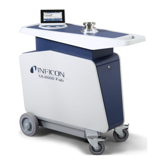
Inficon UL6000 Fab Leak Detector Manuals
Manuals and User Guides for Inficon UL6000 Fab Leak Detector. We have
3
Inficon UL6000 Fab Leak Detector manuals available for free PDF download: Translation Of The Original Operating Instructions, Operating Instructions Manual
Inficon UL6000 Fab Translation Of The Original Operating Instructions (152 pages)
Helium Leak Detector with ULTRATEST Sensor Technology
Brand:
Inficon
| Category:
Security Sensors
| Size: 5.05 MB
Table of Contents
Table of Contents
3
About this Manual
8
Target Groups
8
Warnings
8
Definition of Terms
8
Safety
11
Intended Use
11
Duties of the Operator
13
Owner Requirements
13
Dangers
13
Scope of Delivery, Transport, Storage
15
Description
18
Function
18
Operation Modes
18
Operation Mode "Vacuum
18
Operation Mode "Sniffing
19
Design of Device
20
Overall Device
20
Control Unit
23
START Button
24
STOP Button
24
ZERO Button
25
Meaning of the Button Leds
26
Meaning of the Status LED
26
Design of Touchscreen
27
Vacuum Connections
29
Inlet
29
Exhaust
29
Purge Gas Connection
30
Venting Connection
30
Connections for Accessories and Control Signals
31
Markings on the Device
32
Technical Data
32
Factory Settings
34
Installation
39
Setup
39
Connect the Supplied Accessories
43
Fastening Bracket for Sniffer Line SL3000 (Accessory, Optional)
47
Connect Recipient/Test Object to Inlet Flange
47
Connecting to the Power Supply System
48
Checking the Operation of the Device
49
Operation
51
Switching on
51
Basic Settings
52
Set Language on the User Interface
52
Setting Date, Time and Time Zone
52
User Profile Settings
52
Overview of Rights Groups
52
Select, Modify, Create User Profile
53
Modify Personal Settings
54
Switch off Automatic Login
54
Switch on Automatic Login
54
Presentation of the Measurement Screen
55
Changing the Presentation of the Line Graph
55
Changing the Presentation of the Bar Graph
56
Changing the Presentation of the Circle Graph
57
Change General Display Settings
57
Change Units
58
Change Audio Settings
58
Change the Protection Settings
59
Set Maintenance Interval "Filter Sniffer Tip" or "Air Filter
61
Activate or Deactivate Maintenance Requests
61
Activating or Deactivating Calibration Requests
62
Extending or Reducing Operation Options
62
Measure Internal Calibration Leak after Run-Up
63
Use Favorites
63
Turn Notifications on or off
64
Settings for the Measurements
65
Select Operation Mode
65
Select Gas
65
Setting Setpoints
65
Activate Vacuum Ranges
66
Influence the Speed of the Backing Pump
66
Switch TMP2 Mode on or off
66
Hydro•S
66
Set HYDRO•S
67
Use HYDRO•S
67
Setting the Machine Factor
68
Set External Calibration Leak
68
Change Pressure Limits
68
Set and Use the Function ZERO
69
Vent, Purge, Regenerate
71
Change Leak Rate Filter
72
Change Background Suppression
73
Determine the Background of the Inlet Area
74
Change SL3000 Settings for Sound / Light
74
Change the Sniffer Line Pressure Monitoring
74
Calibrating
75
Internal Calibration
75
External Calibration
76
Check Calibration
76
Measure Internal Calibration Leak
76
Measure
77
Leak Detection with I•RISE™ (Device-Dependent)
78
Measuring Helium Ambient Concentration
80
Measurement Data
81
Switch on Data Recording and Configure Export
81
Display Measurement Cycles
82
Export Measurement Data Via Network
83
Measurement Data Database: Information
84
Information
85
Call the Latest Information to the Current Measurement Value
85
Call the Latest Information to the Current Calibration Value
85
Information on Connected Accessories
85
Retrieve Information about the Device
85
Call Information on the Assemblies
86
Call the Energy Data Information
86
Call Information on the HYDRO•S
86
Call Information on the SL3000 Sniffer Line
87
Log
87
Call the Error and Warning Log
87
Call Calibration Log
87
Call Result Log
87
Call Maintenance Log
87
Device Settings
87
Viewing and Customizing Individual Parameters
87
Saving and Managing Sets of Parameters
88
Exporting or Importing Sets of Parameters
89
Updating the Software
89
Update the User Interface Software
89
Updating the Software of the Basic Unit
90
Update the Software in Expert Mode
91
Activate Additional Function
91
Use External Monitor
91
Switch Back to the Internal Monitor
92
View Vacuum Diagram
92
Resetting to Factory Settings
93
Logging off from the Device
94
Switching off the Device
94
Warning and Error Messages
95
Warning and Error Messages UL3000/UL6000
96
Cleaning and Maintenance
114
Cleaning the Housing
114
Change the Filter Mat Inside the Tool Box
114
Replacement of the Filter Mat on the Bottom of the Device
115
Replacing the SL200 Sniffer Line Filter
116
Replacing the SL3000 Sniffer Line Filter
118
Mounting or Changing the Gas Cylinder
119
Creating Screenshots
120
Have the Device Serviced or Repaired
120
Maintenance Plan
122
Decommissioning
124
Disposing of the Device
124
Returning the Device for Maintenance, Repair or Disposal
124
Accessories and Interfaces
126
Accessories and Spare Parts
126
I/O Module
130
Create a Connection between the Device and the I/O Module
130
Configuring Analog Outputs
130
Configure Digital Inputs
132
Configuring Digital Outputs
133
Setting up the I/O Module Protocol
135
Bus Module
136
Creating a Connection between the Device and the Bus Module
136
Setting a Bus Module Address
136
Network
137
Operate Leak Detector Via Web Browser (LAN)
137
Configure the LAN Connection of the Leak Detector
137
Setting the LAN Connection in the PC or Tablet
138
Allow Client Access
138
Operate Leak Detector Via Web Browser (Wireless LAN)
139
Configure the Wireless LAN Connection of the Leak Detector
139
Setting the Wireless LAN Connection in the PC or Tablet
140
Allow Client Access
141
Appendix
142
Menu Path
142
Diagnosis
142
Settings
142
Information
144
CE Declaration of Conformity
145
Rohs
147
Index
148
Advertisement
Inficon UL6000 Fab Operating Instructions Manual (152 pages)
Helium Leak Detector with ULTRATEST Sensor Technology
Brand:
Inficon
| Category:
Gas Detectors
| Size: 5.05 MB
Table of Contents
Table of Contents
3
About this Manual
8
Target Groups
8
Warnings
8
Definition of Terms
8
Safety
11
Intended Use
11
Duties of the Operator
13
Owner Requirements
13
Dangers
13
Scope of Delivery, Transport, Storage
15
Description
18
Function
18
Operation Modes
18
Operation Mode "Vacuum
18
Operation Mode "Sniffing
19
Design of Device
20
Overall Device
20
Control Unit
23
START Button
24
STOP Button
24
ZERO Button
25
Meaning of the Button Leds
26
Meaning of the Status LED
26
Design of Touchscreen
27
Vacuum Connections
29
Inlet
29
Exhaust
29
Purge Gas Connection
30
Venting Connection
30
Connections for Accessories and Control Signals
31
Markings on the Device
32
Technical Data
32
Factory Settings
34
Installation
39
Setup
39
Connect the Supplied Accessories
43
Fastening Bracket for Sniffer Line SL3000 (Accessory, Optional)
47
Connect Recipient/Test Object to Inlet Flange
47
Connecting to the Power Supply System
48
Checking the Operation of the Device
49
Operation
51
Switching on
51
Basic Settings
52
Set Language on the User Interface
52
Setting Date, Time and Time Zone
52
User Profile Settings
52
Overview of Rights Groups
52
Select, Modify, Create User Profile
53
Modify Personal Settings
54
Switch off Automatic Login
54
Switch on Automatic Login
54
Presentation of the Measurement Screen
55
Changing the Presentation of the Line Graph
55
Changing the Presentation of the Bar Graph
56
Changing the Presentation of the Circle Graph
57
Change General Display Settings
57
Change Units
58
Change Audio Settings
58
Change the Protection Settings
59
Set Maintenance Interval "Filter Sniffer Tip" or "Air Filter
61
Activate or Deactivate Maintenance Requests
61
Activating or Deactivating Calibration Requests
62
Extending or Reducing Operation Options
62
Measure Internal Calibration Leak after Run-Up
63
Use Favorites
63
Turn Notifications on or off
64
Settings for the Measurements
65
Select Operation Mode
65
Select Gas
65
Setting Setpoints
65
Activate Vacuum Ranges
66
Influence the Speed of the Backing Pump
66
Switch TMP2 Mode on or off
66
Hydro•S
66
Set HYDRO•S
67
Use HYDRO•S
67
Setting the Machine Factor
68
Set External Calibration Leak
68
Change Pressure Limits
68
Set and Use the Function ZERO
69
Vent, Purge, Regenerate
71
Change Leak Rate Filter
72
Change Background Suppression
73
Determine the Background of the Inlet Area
74
Change SL3000 Settings for Sound / Light
74
Change the Sniffer Line Pressure Monitoring
74
Calibrating
75
Internal Calibration
75
External Calibration
76
Check Calibration
76
Measure Internal Calibration Leak
76
Measure
77
Leak Detection with I•RISE (Device-Dependent)
78
Measuring Helium Ambient Concentration
80
Measurement Data
81
Switch on Data Recording and Configure Export
81
Display Measurement Cycles
82
Export Measurement Data Via Network
83
Measurement Data Database: Information
84
Information
85
Call the Latest Information to the Current Measurement Value
85
Call the Latest Information to the Current Calibration Value
85
Information on Connected Accessories
85
Retrieve Information about the Device
85
Call Information on the Assemblies
86
Call the Energy Data Information
86
Call Information on the HYDRO•S
86
Call Information on the SL3000 Sniffer Line
87
Log
87
Call the Error and Warning Log
87
Call Calibration Log
87
Call Result Log
87
Call Maintenance Log
87
Device Settings
87
Viewing and Customizing Individual Parameters
87
Saving and Managing Sets of Parameters
88
Exporting or Importing Sets of Parameters
89
Updating the Software
89
Update the User Interface Software
89
Updating the Software of the Basic Unit
90
Update the Software in Expert Mode
91
Activate Additional Function
91
Use External Monitor
91
Switch Back to the Internal Monitor
92
View Vacuum Diagram
92
Resetting to Factory Settings
93
Logging off from the Device
94
Switching off the Device
94
Warning and Error Messages
95
Warning and Error Messages UL3000/UL6000
96
Cleaning and Maintenance
114
Cleaning the Housing
114
Change the Filter Mat Inside the Tool Box
114
Replacement of the Filter Mat on the Bottom of the Device
115
Replacing the SL200 Sniffer Line Filter
116
Replacing the SL3000 Sniffer Line Filter
118
Mounting or Changing the Gas Cylinder
119
Creating Screenshots
120
Have the Device Serviced or Repaired
120
Maintenance Plan
122
Decommissioning
124
Disposing of the Device
124
Returning the Device for Maintenance, Repair or Disposal
124
Accessories and Interfaces
126
Accessories and Spare Parts
126
I/O Module
130
Create a Connection between the Device and the I/O Module
130
Configuring Analog Outputs
130
Configure Digital Inputs
132
Configuring Digital Outputs
133
Setting up the I/O Module Protocol
135
Bus Module
136
Creating a Connection between the Device and the Bus Module
136
Setting a Bus Module Address
136
Network
137
Operate Leak Detector Via Web Browser (LAN)
137
Configure the LAN Connection of the Leak Detector
137
Setting the LAN Connection in the PC or Tablet
138
Allow Client Access
138
Operate Leak Detector Via Web Browser (Wireless LAN)
139
Configure the Wireless LAN Connection of the Leak Detector
139
Setting the Wireless LAN Connection in the PC or Tablet
140
Allow Client Access
141
Appendix
142
Menu Path
142
Diagnosis
142
Settings
142
Information
144
CE Declaration of Conformity
145
Rohs
147
Index
148
Inficon UL6000 Fab Translation Of The Original Operating Instructions (146 pages)
Helium Leak Detector with ULTRATEST Sensor Technology
Brand:
Inficon
| Category:
Security Sensors
| Size: 4.39 MB
Table of Contents
Table of Contents
3
1 About this Manual
8
Target Groups
8
Warnings
8
Definition of Terms
8
2 Safety
11
Intended Use
11
Duties of the Operator
13
Owner Requirements
13
Dangers
14
3 Scope of Delivery, Transport, Storage
15
4 Description
18
Function
18
Operation Modes
18
Operation Mode "Vacuum
18
Operation Mode "Sniffing
19
Design of Device
21
Overall Device
21
Control Unit
24
START Button
25
STOP Button
26
ZERO Button
26
Meaning of the Button Leds
27
Design of Touchscreen
28
Meaning of the Status LED
28
Vacuum Connections
30
Inlet
30
Exhaust
31
Purge Gas Connection
31
Venting Connection
32
Connections for Accessories and Control Signals
33
Markings on the Device
34
Technical Data
34
Factory Settings
36
5 Installation
40
Setup
40
Connect the Supplied Accessories
44
Fastening Bracket for Sniffer Line SL3000 (Accessory, Optional)
48
Connecting to the Power Supply System
49
Checking the Operation of the Device
49
6 Operation
51
Switching on
51
Basic Settings
52
Set Language on the User Interface
52
Setting Date, Time and Time Zone
52
User Profile Settings
52
Overview of Rights Groups
52
Select, Modify, Create User Profile
53
Modify Personal Settings
54
Switch off Automatic Login
54
Switch on Automatic Login
54
Changing the Presentation of the Line Graph
55
Presentation of the Measurement Screen
55
Changing the Presentation of the Bar Graph
56
Change General Display Settings
57
Changing the Presentation of the Circle Graph
57
Change Audio Settings
58
Change Units
58
Change the Protection Settings
59
Activate or Deactivate Maintenance Requests
61
Set Maintenance Interval "Filter Sniffer Tip" or "Air Filter
61
Activating or Deactivating Calibration Requests
62
Extending or Reducing Operation Options
62
Measure Internal Calibration Leak after Run-Up
63
Use Favorites
63
Turn Notifications on or off
64
Settings for the Measurements
65
Select Operation Mode
65
Select Gas
65
Setting Setpoints
65
Activate Vacuum Ranges
66
Switch TMP2 Mode on or off
66
Hydro•S
66
Set HYDRO•S
66
Use HYDRO•S
67
Setting the Machine Factor
67
Set External Calibration Leak
68
Change Pressure Limits
68
Set and Use the Function ZERO
69
Vent, Purge, Regenerate
71
Change Leak Rate Filter
72
Change Background Suppression
72
Determine the Background of the Inlet Area
73
Change SL3000 Settings for Sound / Light
74
Change the Sniffer Line Pressure Monitoring
74
Calibrating
75
External Calibration
75
Internal Calibration
75
Check Calibration
76
Measure Internal Calibration Leak
76
Measure
77
Measuring Helium Ambient Concentration
78
Measurement Data
78
Switch on Data Recording and Configure Export
78
Display Measurement Cycles
79
Export Measurement Data Via Network
80
Measurement Data Database: Information
81
Information
82
Call the Latest Information to the Current Measurement Value
82
Call the Latest Information to the Current Calibration Value
82
Information on Connected Accessories
82
Retrieve Information about the Device
83
Call Information on the Assemblies
83
Call the Energy Data Information
83
Call Information on the HYDRO•S
84
Call Information on the SL3000 Sniffer Line
84
Log
84
Call the Error and Warning Log
84
Call Calibration Log
84
Call Result Log
84
Call Maintenance Log
84
Device Settings
85
Viewing and Customizing Individual Parameters
85
Saving and Managing Sets of Parameters
85
Exporting or Importing Sets of Parameters
86
Updating the Software
86
Update the User Interface Software
87
Updating the Software of the Basic Unit
87
Update the Software in Expert Mode
88
Use External Monitor
88
Switch Back to the Internal Monitor
89
View Vacuum Diagram
89
Resetting to Factory Settings
90
Logging off from the Device
90
Switching off the Device
91
7 Warning and Error Messages
92
Warning and Error Messages UL3000/UL6000
93
8 Cleaning and Maintenance
109
Cleaning the Housing
109
Change the Filter Mat Inside the Tool Box
109
Replacement of the Filter Mat on the Bottom of the Device
110
Replacing the SL200 Sniffer Line Filter
111
Replacing the SL3000 Sniffer Line Filter
113
Creating Screenshots
114
Sending for Repair or Maintenance
115
Maintenance Plan
116
9 Decommissioning
118
Disposing of the Device
118
Sending in the Device
118
10 Accessories and Interfaces
120
Accessories and Spare Parts
120
I/O Module
124
Create a Connection between the Device and the I/O Module
124
Configuring Analog Outputs
124
Configure Digital Inputs
126
Configuring Digital Outputs
127
Setting up the I/O Module Protocol
129
Bus Module
130
Creating a Connection between the Device and the Bus Module
130
Setting a Bus Module Address
130
Network
131
Operate Leak Detector Via Web Browser (LAN)
131
Configure the LAN Connection of the Leak Detector
131
Allow Client Access
132
Setting the LAN Connection in the PC or Tablet
132
Operate Leak Detector Via Web Browser (Wireless LAN)
133
Configure the Wireless LAN Connection of the Leak Detector
133
Setting the Wireless LAN Connection in the PC or Tablet
134
Allow Client Access
135
11 Appendix
136
Menu Path
136
Diagnosis
136
Settings
136
Information
138
CE Declaration of Conformity
139
Rohs
140
Index
141
Advertisement
Advertisement
Related Products
Inficon UL6000 Fab PLUS
Inficon UL5000
Inficon ULTRATEST UL3000 Fab
Inficon ULTRATEST UL3000 Fab PLUS
Inficon UL1000 Fab
Inficon UL1000
Inficon UL3000 Fab ULTRA
Inficon 510-010
Inficon 510-015
Inficon 510-016
Inficon Categories
Security Sensors
Measuring Instruments
Controller
Test Equipment
Gas Detectors
More Inficon Manuals
Login
Sign In
OR
Sign in with Facebook
Sign in with Google
Upload manual
Upload from disk
Upload from URL