
Subscribe to Our Youtube Channel
Related Manuals for Herma 400


Summary of Contents for Herma 400
- Page 1 Operating instructions Label applicator HERMA 400 Geräteschild / type label HERMA GmbH · Geschäftsbereich Maschinen · 70791 Filderstadt · Germany...
- Page 2 HERMA 400 REFACE PERATING INSTRUCTIONS Preface Read and understand all parts of these operating instructions before unpacking, installing or operating on the applicator. They contain important instructions for ensuring your personal safety. These operating instructions must have been read and understood by all persons carrying out work on this applicator in any production phase.
- Page 3 1 on page 12. Copyright © Copyright 2019, HERMA GmbH. The information included in these operating instructions and/or in all of the sections, sub-sections and chapters of them is the intellectual property of the manufacturer and is subject to domestic and international copyright law and other laws for protecting intellectual property.
- Page 4 HERMA 400 OPYRIGHT PERATING INSTRUCTIONS www.herma.com https://machines.herma.com 4/154 3.28 US (130519)
-
Page 5: Table Of Contents
Operating instructions HERMA 400 ABLE OF ONTENTS Table of Contents Overview of the applicator 11 General information 15 Handling of the documentation 15 Explanation of symbols 15 2.2.1 Signal words 15 2.2.2 General designations 16 Safety 17 Important Safety Information 17 3.1.1... - Page 6 Operating instructions HERMA 400 ABLE OF ONTENTS connection 79 Transporting the applicator 79 Installing the applicator 79 Storing the applicator 82 Electrical connection 83 6.4.1 Connections 84 Inserting the label web (web paths) 86 6.5.1 Right-hand applicator with standard dispensing plate 86 6.5.2...
- Page 7 Operating instructions HERMA 400 ABLE OF ONTENTS 9.8.12 140 Start signal 108 9.8.13 141 Start signal Mark field 1 109 9.8.14 142 Start signal Mark field 2 109 9.8.15 143 Start signal Mark field 3 109 9.8.16 144 Start inhibit Start inhibit distance 109 9.8.17...
- Page 8 284 Label check aft. feed 119 9.9.30 285 Lab. check aft. transf. 119 9.9.31 286 Label check start delay 119 9.10 Menu 400 Format 120 9.10.1 410 Format load 120 9.10.2 420 Format save 120 9.10.3 422 Format save Enter name 120 9.10.4...
- Page 9 Operating instructions HERMA 400 ABLE OF ONTENTS 11.2.8 SM114 Transfer unit does not leave home position 135 11.2.9 SM115 Transfer unit does not reach work position 135 11.2.10 SM116 Transfer unit does not leave work position 135 11.2.11 SM119 Label check Error after label feed 135 11.2.12...
- Page 10 Operating instructions HERMA 400 ABLE OF ONTENTS 11.2.59 SM851 Winder failure Temperature too high 140 11.2.60 SM854 Rewinder failure Power stage 140 11.2.61 SM865 Loop filler failure 140 11.2.62 SM910 Drive failure Low voltage 140 11.2.63 SM911 Drive failure High voltage 140 11.2.64...
-
Page 11: Overview Of The Applicator
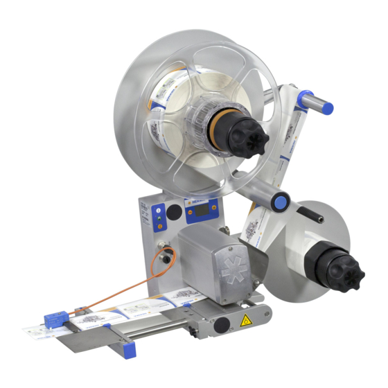
Overview of the applicator On the following pages you can see what your applicator is made up of, can learn > which sub-assemblies the applicator comprises, > how we name different items, > what the functions of the applicator are – and which functions are not intended –, >... - Page 12 HERMA 400 VERVIEW PERATING INSTRUCTIONS Overview Sub-assemblies (see picture): Unwinding the label web (with the help of the „unwinder“; shown here: standard unwinder; alternatively used: motorized version) Tightening the label web (with the help of the „web brake“) Sensing the individual labels on the web (with the help of the „label sensor“; shown here: model FS03;...
- Page 13 lf hazard notification labels are not present, this could lead to injuries. Contact your HERMA representative before energizing your machine Find information on safety messages in chapter 2 as of page 15. Find comprehensive general information on safety in chapter 3 as of page 17.
- Page 14 HERMA 400 VERVIEW PERATING INSTRUCTIONS www.herma.com https://machines.herma.com 14/154 3.28 US (130519)
-
Page 15: General Information
General information Handling of the documentation The operating instructions must be available to all personnel working on the machine at all times. The operating company must ensure that personnel who operate or maintain the system have read and understood all safety instructions, precautionary measures, prohibited behaviour and comments contained in these operating instructions. -
Page 16: General Designations
2 General information Operating instructions HERMA 400 2.2.2 General designations Elements of the HERMA 400 control are designated and depicted in these instructions as follows: Switch-on key Manual feed key Function key LED (on) LED (blinks) LED (off) Minus key... -
Page 17: Safety
Safety Risk of disregarding or neglecting possible dangerous situations or WARNING actions. Read and understand all the safety notes described in the following sections as well as the safety messages found in the rest of these operating instructions Failure to do so could result in serious injury or death and/or property damage. -
Page 18: Mandatory Signs
3 Safety Operating instructions HERMA 400 3.1.2 Mandatory signs The signs shown here indicate that the operation must be performed without fail / the information is mandatory to take notice of. Cut the applicator / the machine off mains. Make sure to tie up long hair (if required, wear a hair net) and avoid wide clothing. -
Page 19: Symbols On The Applicator
3 Operating instructions HERMA 400 AFETY Symbols on the applicator These symbols / hazard notification labels are used on the applicator. Missing safety labels could lead to disregarding possible dangerous CAUTION situations. Ensure that all symbols and signs are in a condition that is easy to read at all times. -
Page 20: Proper Use Of The Applicator
3 Safety Operating instructions HERMA 400 Proper use of the applicator Risk due to using the applictor in a way that is not intended. Always use WARNING the applicator only for its intended use, which is unwinding label rolls, dispensing labels and rewindig the backing paper. Any use other than the... -
Page 21: Responsibility Of The Operator
3 Operating instructions HERMA 400 AFETY Responsibility of the operator Operator ... is any person who operates or allows a third party to operate the machine for industrial or commercial purposes and who bears legal responsibility for the product with regard to protecting the user or third parties during its operation. -
Page 22: Personnel
Trained persons have read and understood these operating instructions and have access to these instructions at any time. Trained persons should have have been instructed for working at the applicator by HERMA GmbH, or by a HERMA partner. > Allow only trained persons to install, use, service and work on the label applicator. -
Page 23: Applicator Description
Applicator description In this chapter you will find an overview of the applicator HERMA 400 and its sub-assemblies. Overview For an overview of the applicator HERMA 400 see chapter 1, page 12. Sub-assemblies Risk of electric shock. 110-240 Volts may be present and could cause DANGER electrocution. -
Page 24: Standard Unwinder
4 Applicator description Operating instructions HERMA 400 4.1.1 Standard unwinder Rotating part. Do not reach into the area of this unit when the applicator is CAUTION on. There is the risk of being caught or getting entangled. Inserting the label web >... - Page 25 4 Operating instructions HERMA 400 PPLICATOR DESCRIPTION Adjusting the reel brake (basic adjustment) The point of activation of the unwinder’s reel brake is factory-set and usually does not have to be changed. If however the label reel is too loose (activation point too late) or only moves at strong pull (activation point premature) a new basic adjustment is required.
- Page 26 4 Applicator description Operating instructions HERMA 400 Replacing the proximity switch If your unwinder is equipped with a proximity switch for detecting end of reel proceed as follows when replacing a defective switch: Risk of electric shock! Disconnect all sources of supply and wait for five...
- Page 27 4 Operating instructions HERMA 400 PPLICATOR DESCRIPTION Replacing the tension rings If after a long time of use tension rings 11 are worn proceed as follows when preplacing the worn rings (example with constructional width 16, vertical applicator): > Remove handle 1, as described above („Replacing the handle“).
-
Page 28: Motorized Unwinder - Slim Line Version
4 Applicator description Operating instructions HERMA 400 4.1.2 Motorized unwinder – Slim line version Rotating part. Do not reach into the area of this unit when the applicator is CAUTION on. There is the risk of being caught or getting entangled. - Page 29 4 Operating instructions HERMA 400 PPLICATOR DESCRIPTION Teaching the angle sensor As the case may be, e.g. in case of a new unit, you may have to teach the unit the positions of the pendulum if this is released completely and if this is moved to its maximum deflection in order to ensure a correct function and to avoid errors.
- Page 30 4 Applicator description Operating instructions HERMA 400 Error codes Error codes, i.e,. blink codes, can be acknowledged and reset by pressing the illuminated button briefly. The following codes may appear: Blinking Cause Unwinding without movement of pendulum (unwinder protection). The pendulum remains in its position too long. Check parameters 958 and 959.
- Page 31 Determine the size of the unit (Ø of the take-up disk) On – On: 600 mm (23.6’’) On – Off: 400 mm (16’’) (choose this setting with the magazine filler) Off – On: 500 mm (19.7’’) Off – Off: 300 mm (12’’) (choose this setting with the loop unit)
- Page 32 4 Applicator description Operating instructions HERMA 400 DIP switch Configuration Switch 8 Determines the pre-set sense of rotation of the unit, seen fro the front side of the unit, facing to the disc / the roller (Motorised unwinder: any change is to be effected with the illuminated button).
- Page 33 4 Operating instructions HERMA 400 PPLICATOR DESCRIPTION > Remove disk 10 (fig. F). The motor is now held only by plug 11 (fig. G). Loosen the plug and remove the motor. The circuit board can be removed carefully. To do so first lift it at the side opposite to button 12 ...
-
Page 34: Motorized Loop-Type Unwinder - Slim Line Version
4 Applicator description Operating instructions HERMA 400 4.1.3 Motorized loop-type unwinder – Slim line version Inserting the label web > Insert the label reel such that the labels reach the dispensing beak in the correct position. > Insert the web according to the schemes shown in section 6.5.9. Turn the unit on/off with switch / illuminated button a. - Page 35 4 Operating instructions HERMA 400 PPLICATOR DESCRIPTION Functions of the illuminated button There are several functions for the illuminated button a: – Switching the unit on/off – Error indication via blink codes For these functions see the following table, or respective sections.
- Page 36 Determine the size of the unit (Ø of the take-up disk) On – On: 600 mm (23.6’’) On – Off: 400 mm (16’’) (choose this setting with the magazine filler) Off – On: 500 mm (19.7’’) Off – Off: 300 mm (12’’) (choose this setting with the loop unit)
- Page 37 4 Operating instructions HERMA 400 PPLICATOR DESCRIPTION DIP switch Configuration Switch 8 Determines the pre-set sense of rotation of the unit, seen fro the front side of the unit, facing to the disc / the roller (Motorised unwinder: any change is to be effected with the illuminated button).
- Page 38 4 Applicator description Operating instructions HERMA 400 Changing parts Risk of electric shock! Disconnect all sources of supply and wait for five DANGER minutes before opening the rear cover or touching the connector pins! Electrocution may occur. If you need to replace parts proceed as follows: >...
-
Page 39: Label Web Brake
4 Operating instructions HERMA 400 PPLICATOR DESCRIPTION 4.1.4 Label web brake Rotating part. Do not reach into the area where the feed roller draws in the WARNING web when machine is on! There is the risk of being caught or getting entangled. - Page 40 4 Applicator description Operating instructions HERMA 400 > D/E: Loosen screw 1. Turn adjusting plate 2 to the left or to the right until label web passes below the brake plate smoothly, but with perceptible resistance. Tighten screw 1. Cleaning ...
-
Page 41: Label Sensor Fs03
4 Operating instructions HERMA 400 PPLICATOR DESCRIPTION 4.1.5 Label sensor FS03 Set button 680297 The label sensor FS03 is a self-learning unit, suitable for paper labels as well as electrically conducting labels (metallized or aluminium-covered). The unit is set such that the sensor is high-active on the label (1-signal on the label). -
Page 42: Setting Mode
4 Applicator description Operating instructions HERMA 400 Positioning the label Depending on the application labels have to be peeled off completely (for suction), or a small part of the label remains attached to the backing paper (for tearing off, i.e. the product „takes“ the label), or a small part of the label is peeled off and most of it remains attached to the backing paper (for labeling with synchronous parallel motion). - Page 43 4 Operating instructions HERMA 400 PPLICATOR DESCRIPTION Overview Buttonpress <2s >2s, <10s >10s, <15s >15s, <20s >20s Function Basic state Teaching Label material Offset Factory setting (off) (on) (blinking) (off) (on) — after end of after 10s after 10s after end of...
- Page 44 4 Applicator description Operating instructions HERMA 400 Buttonpress Function triggered / activated duration >15s, <20s LED is off , adjusting the offset. After releasing the button a blink sequence indicates the offset currently set (the standard value for paper labels is 6, for metal labels 10).
- Page 45 4 Operating instructions HERMA 400 PPLICATOR DESCRIPTION Technical Data Operating voltage: 15 – 30V DC Rated current consumption: 25mA Output current: max. 20mA Output voltage low/high: 2.5V / UB - 3.5V Temperature (operation/storage): 0 – 50°C / -20 – +80°C...
-
Page 46: Label Sensor Optoelectronic
4 Applicator description Operating instructions HERMA 400 4.1.6 Label sensor optoelectronic Cross adjustment > Loosen knurled nut 8. > Move scanning spot of photoelectric cell 1 (see locating mark) over passing label web. > In case of round labels the scanning spot should be positioned over the label centerline. - Page 47 4 Operating instructions HERMA 400 PPLICATOR DESCRIPTION Positioning the label Depending on the application labels have to be peeled off completely (for suction), or a small part of the label remains attached to the backing paper (for tearing off, i.e. the product „takes“ the label), or a small part of the label is peeled off and most of it remains attached to the backing paper (for labeling with synchronous parallel motion).
-
Page 48: Dispensing Sytems
4 Applicator description Operating instructions HERMA 400 4.1.7 Dispensing sytems Explanations / Illustrations for threading the label web you will find in section 6.5. Rigid/Straight dispensing plates Dispensing plate straight Dispensing plate straight, Dispensing plate, 75° angular with application roller Adjusting the dispensing plate >... -
Page 49: Dispensing Plate, 15° Angular
4 Operating instructions HERMA 400 PPLICATOR DESCRIPTION Dispensing plate, 15° angular Inserting the label web > Pull snaplock 1. Fold up holding-down plate 2. > Pass label web below guide roller 3 and holding-down plate 2. Run backing paper back around the dispensing plate 4 and guide roller 5. -
Page 50: Pivot Beak / Application Unit
4 Applicator description Operating instructions HERMA 400 Pivot beak / Application unit Pivot beak Application unit Adjusting the pivot beak / the application unit > Adjust paper guide 1 such that the label web sits close to screw head 2 and paper guide 1. -
Page 51: Moving Beak
4 Operating instructions HERMA 400 PPLICATOR DESCRIPTION Moving beak Pneumatic working pressure must not exceed 5 bar. Do not reach into the CAUTION area of the unit during operation. The movement of the unit could cause injuries! Inserting the label web >... -
Page 52: Transfer Systems
4 Applicator description Operating instructions HERMA 400 4.1.8 Transfer systems Telescope One of several possible telescopes (linear units) may be used in your machine, depending on the application. These units are maintenance-free. Take notice of the following: Pneumatic working pressure must not exceed 5 bar. Do not reach into the CAUTION area of the unit during operation. -
Page 53: Transverse Transfer System
4 Operating instructions HERMA 400 PPLICATOR DESCRIPTION Transverse transfer system Pneumatic working pressure must not exceed 5 bar. Do not reach into the CAUTION area of the unit during operation. The movement of the unit could cause injuries! Inserting the label web A Unlock the dispensing plate 2 by pulling the two snap- in knobs 1 simultaneously. - Page 54 4 Applicator description Operating instructions HERMA 400 Adjusting the dispensing position The label, in order to be ready for pick-up by the suction plate, must be fully detached from the backing paper. Adjust the correct position (i.e. to what extent the label is to be peeled off the backing paper when dispensed) according to the description in section „Positioning the label“...
- Page 55 4 Operating instructions HERMA 400 PPLICATOR DESCRIPTION I You can mount the pressure indicator in two different positions to ensure best readability. Fix the unit in position c or d. Changing the suction plate J – K > Remove pneumatic hose from the suction plate. For this purpose press the blue collar 15 when pulling.
- Page 56 4 Applicator description Operating instructions HERMA 400 Make sure to adjust the braking plate pressure when reassembling such that the label web is felt to pass freely but against perceptible resistance. Clean the suction plate if required. 56/154 3.28 US (130519)
-
Page 57: Drive/Transport Roller
4 Operating instructions HERMA 400 PPLICATOR DESCRIPTION 4.1.9 Drive/Transport roller Rotating part. Do not reach into the area where the feed roller draws in the WARNING web when machine is on! There is the risk of being caught or getting entangled. -
Page 58: Standard Rewinder
4 Applicator description Operating instructions HERMA 400 4.1.10 Standard rewinder Rotating part. Do not reach into the area of this unit when the applicator is CAUTION on. There is the risk of being caught or getting entangled. Inserting the backing paper >... - Page 59 4 Operating instructions HERMA 400 PPLICATOR DESCRIPTION Basic adjustment of the lever If after a very long time of use rewinding does not function reliably anymore proceed as follows when effecting the basic adjustment: > Remove take-up roll (roll including disk) after loosening screw 14.
- Page 60 4 Applicator description Operating instructions HERMA 400 > Deflect lever 20 widely. Tighten clamping screw 18 slightly (not completely) such that the lever remains deflected after letting go but still can be turned manually. Make sure at the same time that clamping piece 17 is fixed on the shaft without play.
- Page 61 4 Operating instructions HERMA 400 PPLICATOR DESCRIPTION Replacing the handle If after a very long time of use clamping of the backing paper with handle 1 does not function properly anymore proceed as follows when preplacing a worn handle: >...
- Page 62 4 Applicator description Operating instructions HERMA 400 > Remove sleeve 3 after removing screw 14. > Pull off remaining parts. When remounting the core sleeve in reverse order with the new tension rings make sure that the screws (12, 14) together with the plug-in parts 15 (with pins) are aligned exactly onto the respective holes 16.
- Page 63 4 Operating instructions HERMA 400 PPLICATOR DESCRIPTION Replacing the round belt Risk of electric shock! Disconnect all sources of supply and wait for five DANGER minutes before opening the rear cover or touching the connector pins! Electrocution may occur. Take the belt from tension pulley B, then from roller A and subsequently from roller C. ...
-
Page 64: Motorized Rewinder - Slim Line Version
4 Applicator description Operating instructions HERMA 400 4.1.11 Motorized rewinder – Slim line version Rotating part. Do not reach into the area of this unit when the applicator is CAUTION on. There is the risk of being caught or getting entangled. - Page 65 4 Operating instructions HERMA 400 PPLICATOR DESCRIPTION Inserting the backing paper For an overview see also sections 6.5.7 and 6.5.8. > Turn handle 1 completely to the left (maximum of five steps) to unclamp the unit. > Run backing paper around bar 2.
- Page 66 4 Applicator description Operating instructions HERMA 400 Replacing the tension rings If after a very long time of use tension rings 11 are worn proceed as follows when preplacing the worn rings (example with constructional width 24): > Remove sleeve 2 after removing screw 12.
- Page 67 4 Operating instructions HERMA 400 PPLICATOR DESCRIPTION When remounting the core sleeve in reverse order with the new tension rings make sure that the screws (12, 14) together with the plug-in parts 15 (with pins) are aligned exactly onto the respective holes 16.
- Page 68 4 Applicator description Operating instructions HERMA 400 Functions of the illuminated button There are several functions for the illuminated button a: – Switching the unit on/off – Teaching the angle sensor – Error indication via blink codes For these functions see the following table, or respective sections.
- Page 69 4 Operating instructions HERMA 400 PPLICATOR DESCRIPTION The factory-set maximum deflection of the pendulum may constructionally NOTICE be decreased by a maximum of 20° since otherwise full functionality cannot be assured. Error code Error codes, i.e,. blink codes, can be acknowledged and reset by pressing the illuminated button briefly.
- Page 70 Determine the size of the unit (Ø of the take-up disk) On – On: 600 mm (23.6’’) On – Off: 400 mm (16’’) (choose this setting with the magazine filler) Off – On: 500 mm (19.7’’) Off – Off: 300 mm (12’’) (choose this setting with the loop unit)
- Page 71 4 Operating instructions HERMA 400 PPLICATOR DESCRIPTION DIP switch Configuration Off – On: not defined Off – Off: 3’’ (76 mm) (choose this setting with the loop unit and with the magazine filler) Switch 7 Determines the pendulum type of the unit / the size of the chute with the...
- Page 72 4 Applicator description Operating instructions HERMA 400 > Gear 6 is accessible (fig. D). Place two Allen screws M3x5 (DIN912) into holes 7 (functions as pulling-off device). Remove torx screw 8 (you have to overcome a certain resistance). Make sure to hold the motor at the same time.
-
Page 73: Technical Data
Power supply / Line voltage Wide range input 100V AC ... 240V AC ±10%, 50 Hz ... 60 Hz Max. power consumption 400 W + n times 100W (n=number of motorized winder units) Leakage current, according to EN 60335-1 110VAC: <0.35 mA... - Page 74 5 Technical Data Operating instructions HERMA 400 Weight Customer-specific; see section 5.1 below for examples Winder system SlimLine Max. reel width for reel diameter of 16’’: 12.6’’ (400 mm: 320 mm) 20’’: 7.8’’ (500 mm: 200 mm) 23.6’’: 6.3’’ (600 mm: 160 mm) Max.
-
Page 75: Dimensions / Weight (Configuration Examples)
5 Operating instructions HERMA 400 ECHNICAL Dimensions / weight (configuration examples) 653.5 mm (25.73”) Weight: approx. 35 lb (16 kg) 944 mm (37.17”) Anlaufkante Weight: approx. 66 lb (30 kg) 75/154 3.28 US (130519) -
Page 76: Inputs / Outputs (X10) (Option, Standard Signals)
5 Technical Data Operating instructions HERMA 400 Inputs / outputs (X10) (option, standard signals) This optional connector provides inputs/outputs to the external control (e.g. PLC). ➜97941 Designation Description Color Led3 brown X22.8 LED function key (printer status) Ground (all voltages DC) blue X22.2... -
Page 77: Inputs / Outputs (X19) (Option, Extended Signals)
5 Operating instructions HERMA 400 ECHNICAL Inputs / outputs (X19) (option, extended signals) This optional connector provides inputs/outputs to the external control (e.g. PLC). ➜97941 Designation Description Color +24V Power supply (<150mA) brown X31.9 Ground (all voltages DC) blue X31.2 X29.2... - Page 78 5 Technical Data Operating instructions HERMA 400 www.herma.com https://machines.herma.com 78/154 3.28 US (130519)
-
Page 79: Transport, Installation, Storage And
WARNING when switched on. Mount the applicator appropriately before supplying energy. Otherwise this could lead to serious injury. If you should notice damage due to transport when you unpack the machine inform your HERMA sales office immediately. 79/154 3.28 US (130519) - Page 80 6 Transport, installation, storage and connection Operating instructions HERMA 400 Only use the machine in dry areas. WARNING Mount the applicator appropriately before supplying energy. If persons that were not properly instructed for using the applicator various risks may occur. Installation/removal shall only be performed by trained specialists when the applicator is disconnected from the mains supply.
- Page 81 6 Operating instructions HERMA 400 RANSPORT INSTALLATION STORAGE AND CONNECTION Pedestal 30 horizontal. Fix with 4 x M6. 4 x M6 provided by customer. Pedestal 30 with short leg. Pedestal 30 with long leg. Fix with 5 x M6. ...
-
Page 82: Storing The Applicator
6 Transport, installation, storage and connection Operating instructions HERMA 400 Storing the applicator > Never store the applicator outdoors, where it is exposed to the impact of weather conditions. > Store the applicator in a dry and dust-free environment. >... -
Page 83: Electrical Connection
Risk of connecting the applicator to an electical system that is not suitable for using the appliance safely. HERMA 400 applicators are designed for connection to and operation on a TN-C-S electrical system. Appropriate technical measures must be taken before use on other types of electrical system. ... -
Page 84: Connections
6 Transport, installation, storage and connection Operating instructions HERMA 400 6.4.1 Connections The following connections are available at the HERMA 400 applicator (depending on the configuration): X14 ( ) /(X16 (special) † X13 (all types) X16 ( ) / X19 (... - Page 85 6 Operating instructions HERMA 400 RANSPORT INSTALLATION STORAGE AND CONNECTION With motorized unwinders the signals for end of reel and diminishing reel can be detected at the same time only if the unwinder is connected via CAN bus (X18). Detection of these web signals is effected automatically.
-
Page 86: Inserting The Label Web (Web Paths)
6 Transport, installation, storage and connection Operating instructions HERMA 400 Inserting the label web (web paths) Before inserting the label web, ensure that the applicator/machine is CAUTION switched off. The following schemes show how to insert the label web with the most common standard applicators. -
Page 87: Right-Hand Applicator With Pivot Beak
6 Operating instructions HERMA 400 RANSPORT INSTALLATION STORAGE AND CONNECTION 6.5.3 Right-hand applicator with pivot beak 681299 681299 0 = Außenwicklung / outside winding O = Außenwicklung / outside winding I = Innenwicklung / inside winding I = Innenwicklung / inside winding 6.5.4... -
Page 88: Right-Hand Applicator With Dispensing Plate With Spring-Loaded Roller, 75° Angular
6 Transport, installation, storage and connection Operating instructions HERMA 400 6.5.5 Right-hand applicator with dispensing plate with spring-loaded roller, 75° angu- 681300 681300 0 = Außenwicklung / outside winding O = Außenwicklung / outside winding I = Innenwicklung / inside winding I = Innenwicklung / inside winding 6.5.6... -
Page 89: Winder System, Left-Hand Applicator
6 Operating instructions HERMA 400 RANSPORT INSTALLATION STORAGE AND CONNECTION 6.5.7 Winder system, left-hand applicator Unwinder Rewinder * The winder system is a moduar system consisting of the individual components of unwinder, loop- type unwinder and backing paper take up unit (rewinder), each of which is motor driven . See sections 4.1.2, 4.1.3 and 4.1.11. -
Page 90: Winder System, Right-Hand Applicator
6 Transport, installation, storage and connection Operating instructions HERMA 400 6.5.8 Winder system, right-hand applicator Unwinder Rewinder 90/154 3.28 US (130519) -
Page 91: Winder System, Loop-Type Unwinder
6 Operating instructions HERMA 400 RANSPORT INSTALLATION STORAGE AND CONNECTION 6.5.9 Winder system, loop-type unwinder Type 4 L/R Type 7 L/R Type 5 L/R 91/154 3.28 US (130519) - Page 92 6 Transport, installation, storage and connection Operating instructions HERMA 400 www.herma.com https://machines.herma.com 92/154 3.28 US (130519)
-
Page 93: Putting Into Operation
Putting into operation Observe all safety regulations at your site as well as the safety notes WARNING outlined in chapter 3 as of page 17 when switching on the applicator. If the applicator does not have a power plug, the unit must only be connected by a qualified electrician in accordance with national and local electrical codes. - Page 94 7 Putting into operation Operating instructions HERMA 400 www.herma.com https://machines.herma.com 94/154 3.28 US (130519)
-
Page 95: Putting Out Of Operation
Putting out of operation If the applicator does not have a power plug, the unit must only be WARNING disconnected by a qualified electrician in accordance with national and local electrical codes. Observe the wlrlng diagram included wlth the documentation. Applicators which are part of a larger machine structure are usually switched off with the main switch for the entire setup (see also the respective separate manual for that machine). - Page 96 8 Putting out of operation Operating instructions HERMA 400 www.herma.com https://machines.herma.com 96/154 3.28 US (130519)
-
Page 97: Herma 400 Control)
Operation (via the HERMA 400 control) General designations Elements of the HERMA 400 control are designated and depicted in this chapter as follows: Switch-on key Manual feed key Function key LED (on) LED (blinks) LED (off) Minus key Plus key Enter key Find further explanation on these elements in section 9.1. -
Page 98: Design (Keypad And Display)
9 Operation (via the HERMA 400 control) Operating instructions HERMA 400 Design (keypad and display) Applicators HERMA 400 are operated via the keys of the key pad and the display. The display allows entry and adjustment of applicator parameters. Basic values, such as e.g. the start delay of the applicator, may be set either here or as well via optional potentiometers (in an external housing or in the control box). - Page 99 9 Operating instructions HERMA 400 HERMA 400 PERATION VIA THE CONTROL Printer ON/OFF (2x) An optional printer can be switched on and off with the function key, pressing it quickly two times („double tip“). If the printer is ON the function „compensate for missing labels“ is active at the same time.
-
Page 100: Function Diagram
9 Operation (via the HERMA 400 control) Operating instructions HERMA 400 Display The display is activated with applying mains and will show one of two possible variants of the basic display image: STANDBY READY H400 V H400 V Vz.xx.yy Vz.xx.yy... -
Page 101: End Of Reel And Diminishing Reel (Internal)
End of reel End of reel (END signal) is triggered if the label supply is used up, however not before a minimum transport of approx. 16“ / 400 mm (with preceding DIM signal after 5.9“ / 150 mm already). End of reel... -
Page 102: Overview Display Structure Herma
9 Operation (via the HERMA 400 control) Operating instructions HERMA 400 Overview display structure HERMA 400 Standby / Ready Quick menu: Format loading ...optional, if activated... Start delay Stop delay Label speed Product speed Configuration ... -
Page 103: The Display's Quick Menu
9 Operating instructions HERMA 400 HERMA 400 PERATION VIA THE CONTROL The display’s Quick Menu As soon as the key is pressed while the basic display image is shown all parameters and submenus of the so-called Quick Menu are shown. In this Quick Menu you will find the basic values for the applicator’s start delay, the labels’... -
Page 104: Start Delay Applicator (Quick Menu Parameter)
9 Operation (via the HERMA 400 control) Operating instructions HERMA 400 9.5.2 Start delay applicator (Quick Menu parameter) 2.0 mm Select Range: 0–800 mm (no function with This basic value determines the delay between start signal and actual start of label transport. -
Page 105: Speed Of The Applicator (Quick Menu Parameter)
9 Operating instructions HERMA 400 HERMA 400 PERATION VIA THE CONTROL 9.5.5 Speed of the applicator (Quick Menu parameter) 36.0 m/min Select Range: 3–20, 3–30, 3–40, 3–80, 0–120 m/min With the help of this parameter the speed of the label web can be adjusted. Minimum and maximum speeds correspond to the performance of the drive used. -
Page 106: Potentiometers
9 Operation (via the HERMA 400 control) Operating instructions HERMA 400 Potentiometers Basic values of the applicator may optionally be adjusted via potentiometers as well (analog input). In that case this will be shown in the display: Analog ... -
Page 107: Menu 100 Basic Data
9 Operating instructions HERMA 400 HERMA 400 PERATION VIA THE CONTROL Menu 100 Basic data 9.8.1 115 Master enc. transfer This parameter will appear only if parameter 110 (available only for Technical Service) is set to „02 Master encoder“. With PWL2 only. this and the two following parameters are for all application types except for rigid beak, pivot beak and type 211. -
Page 108: Master Encoder Stop Compensation
9 Operation (via the HERMA 400 control) Operating instructions HERMA 400 9.8.6 123 Master encoder Stop compensation This parameter will appear only if parameter 110 (available only for Technical Service) is set to „02 Master encoder“. With PWL2 only. Setting the dead time of the stop sensor (label sensor) in order to compensate for the resulting delay. -
Page 109: Start Signal Mark Field 1
9 Operating instructions HERMA 400 HERMA 400 PERATION VIA THE CONTROL inhibit: Start Start of web transport is inhibited on a distance determined with parameter 144. edge: Falling Web transport is started with detecting the falling edge of the label. -
Page 110: Stop Signal
9 Operation (via the HERMA 400 control) Operating instructions HERMA 400 9.8.19 180 Stop signal (stand.): Rising edge Web transport is stopped with the rising edge of the label. mark: Sensor Web transport is stopped on detection of a sensor mark. Use parameters 131 through 133 for specifying. -
Page 111: Stop Sensor Label Position
9 Operating instructions HERMA 400 HERMA 400 PERATION VIA THE CONTROL The maximum deviation tolerance with activated quality monitoring. If this tolerance is exceeded further labeling processes will be stopped and a corresponding error message generated. See also section „944 Monitoring quality“ on page 123. -
Page 112: Printer Print Time
9 Operation (via the HERMA 400 control) Operating instructions HERMA 400 9.8.32 195 Printer Print time The time in milliseconds given for one print process, if the printing mode is set to „Standstill“ (adjustable with PWL3 only). Note: This time will have no effect when using the hot-foil printer Allen Compact 40/20 CL and thus is in such case always to be set to 10 ms. -
Page 113: Menu 200 Transfer Data
9 Operating instructions HERMA 400 HERMA 400 PERATION VIA THE CONTROL Menu 200 Transfer data 9.9.1 201 Application type As factory setting one of the following application types is selected via parameter 201 (available for Technical Service only): 00 Rigid beak: Using a „normal“... -
Page 114: Pivot Beak On/Off
9 Operation (via the HERMA 400 control) Operating instructions HERMA 400 ————————The following parameters will appear only if parameter 201 (available only for Technical Service) is set to „X17: Pivot beak“.———————— 9.9.2 210 Pivot beak on/off Switch the optional pivot beak on or off. -
Page 115: Roller Unit Start Delay
9 Operating instructions HERMA 400 HERMA 400 PERATION VIA THE CONTROL ————————The following parameters will appear only if parameter 201 (available only for Technical Service) is set to „CAN: Type 211“.———————— 9.9.7 217 Roller unit start delay This parameter will appear only if parameter 201 (available only for Technical Service) is set to „CAN:... -
Page 116: Dispensing Unit Label Start Delay
9 Operation (via the HERMA 400 control) Operating instructions HERMA 400 ————————The following parameters will appear only if parameter 201 (available only for Technical Service) is set to options with moving beak and/or transfer unit and/or Blow box, e.g. to „CAN: Mov. -
Page 117: Prism Control System
9 Operating instructions HERMA 400 HERMA 400 PERATION VIA THE CONTROL ————————The following parameters will appear only if parameter 201 (available only for Technical Service) is set to „CAN: Type 152“.———————— 9.9.18 260 Prism control system Standard: The prism is activated after product recognition and a configurable start delay (parameter 263). Upon expiry of the start delay in the quick menu, the labeling process is started. -
Page 118: Auxiliary Control System
9 Operation (via the HERMA 400 control) Operating instructions HERMA 400 9.9.25 267 Auxiliary control system An additional output can be activated for special applications, e.g. a hold-down clamp. To enable universal use of this output, the trigger can be controlled by different events. -
Page 119: Label Check On / Off
9 Operating instructions HERMA 400 HERMA 400 PERATION VIA THE CONTROL 9.9.28 280 Label check on / off Activate or deactivate a missing label control (directly via sensor or indirectly via vacuum monitoring). 9.9.29 284 Label check aft. feed With PWL2 and activated label check only. ... -
Page 120: Menu 400 Format
9 Operation (via the HERMA 400 control) Operating instructions HERMA 400 9.10 Menu 400 Format Parameters that are set in the applicator can be named and saved in this menu, several parameter sets/configurations (up to 30) for different applications can be created, and these parameter sets/ configurations, called „formats“... -
Page 121: Menu 500 Batch
9 Operating instructions HERMA 400 HERMA 400 PERATION VIA THE CONTROL 9.11 Menu 500 Batch 9.11.1 510 Batch size If required activate a batch counter here. To do so enter a value higher than 0. After pressing arrow directing downwards appears above the digits of the batch counter. Use the... -
Page 122: Menu 900 System
9 Operation (via the HERMA 400 control) Operating instructions HERMA 400 9.12 Menu 900 System 9.12.1 910 Rotate display drehen Rotate the display by 180° if required. 9.12.2 912 Sprache / Language Set the display’s language to one of the languages available. -
Page 123: Alarm Message After Missing Labels
9 Operating instructions HERMA 400 HERMA 400 PERATION VIA THE CONTROL 03 Actual (large), Batch: Display of the actual number of produced products in large letters and the batch size. READY Actual: p/min Batch: 0000000 Menu 04 Left (large), Batch: Display of what is left to be produced in large letters and the batch size. -
Page 124: Unwinder Disc
9 Operation (via the HERMA 400 control) Operating instructions HERMA 400 02 Medium: Here, minor changes of the label overfeed are accepted. Distances will conform with average values that are continuously determined anew. 03 Little: With this setting an error messge is issued if several labelling processes in a row are out of tolerance. -
Page 125: Unwinder Oper. Modes
9 Operating instructions HERMA 400 HERMA 400 PERATION VIA THE CONTROL 9.12.15 950 Unwinder oper. modes With PWL2 only. Enter her the operating mode of the unwinder as follows: 00 Standard: This is the normal mode of the unwinder with penulum control. -
Page 126: Loop Unwinder
9 Operation (via the HERMA 400 control) Operating instructions HERMA 400 With the %-specification the drive behaviour with respect to acceleration and deceleration can be preset. 100 % corresponds to hard acceleration and deceleration, 30 % corresponds to a very low acceleration and deceleration. -
Page 127: Loop Unwinder Output
9 Operating instructions HERMA 400 HERMA 400 PERATION VIA THE CONTROL „Fix“ settings: Here the drive is constantly operated with the same preset acceleration. The final speed must be determined with the help of parameter 953. Example setting 05: Here the drive is set to highest dynamic. This setting will always be maintained. -
Page 128: Unwinder Mode
9 Operation (via the HERMA 400 control) Operating instructions HERMA 400 Parameter 952 with 05 Fix: **********, parameter 953 with 100%. For small label feeds at moderate speed and sensitive label web this parameter setting may deliver good results: Parameter 952 with... -
Page 129: Unwinder Protection 1
9 Operating instructions HERMA 400 HERMA 400 PERATION VIA THE CONTROL 07 100% (O): 08 90% (S): 09 90% (T): 10 90% (O): 11 70% (S): 12 70% (T): 13 70% (O): 14 60% (S): Soft 15 60% (T): 9.12.23 958 Unwinder protection 1 With PWL2 only. -
Page 130: Display Add. Output
9 Operation (via the HERMA 400 control) Operating instructions HERMA 400 Address 01 thru 20 for applicator in field bus operation Address 21 thru 28 for applicator with config protocol. A change in address will be effective only after the applicator was switched off. When using a RS232 interface the applicator will react to any address. -
Page 131: Cleaning, Maintenance, Service
Electrocution may occur. > Use suitable gripping tool for removing and inserting. 97942 See chapter 5 for fuse specifications. Important: Opening the screws at the front of the drive unit HERMA 400 will NOTICE void the warranty! 131/154 3.28 US (130519) -
Page 132: Maintenance Schedule
10 Cleaning, maintenance, service Operating instructions HERMA 400 10.1 Maintenance schedule Recommended Maintenance task interval Daily Dispensing beak / plate Remove adhesive residue Transport roller Remove adhesive residue and clean. For details see section 4.1.9, page 57. Brake plate... -
Page 133: Troubleshooting
Troubleshooting 11.1 Indication of malfunctions With HERMA 400 applicators the type of malfunction is indicated via the display (see section 11.2). Also, the LEDs of the key pad will give an indication (see section 11.3 „Malfunction table (LED indication)“). Furthermore there is the possibility to connect a signal coumn to X10. With the usual allocation red stands for malfunction, yellow for warning, and green for production. -
Page 134: List Of Malfunctions (Indicated Via Display)
11 Troubleshooting Operating instructions HERMA 400 11.2 List of malfunctions (indicated via display) Malfunctions are indicated with a three-digit number after the text „SM“. The next line will contain the actual text of the malfunction. SM910: Drive failure Low voltage... - Page 135 11 Operating instructions HERMA 400 ROUBLESHOOTING 11.2.8 SM114 Transfer unit does not leave home position There are sensors that check the positions of this component. If one of these positions is not reached or left in time a corresponding message will appear. These problems usually have some mechanical cause which you will easily detect.
- Page 136 11 Troubleshooting Operating instructions HERMA 400 – Label sensor should be positioned at least 2 mm behind the rising edge of the label gap Label should not protrude more than approx. 1 mm beyond the beak (else the product may catch the label on passing the labeling station).
- Page 137 11 Operating instructions HERMA 400 ROUBLESHOOTING 11.2.24 SM167 Roller unit Error This message appears if there is an error at the roller motor (roller prism, type 211). Maybe something is blocked. After remedying first acknowledge at the roller unit and then at the main unit.
- Page 138 SM198 CAN communikation Response time This message appears if the response to a switching operation took too long. Please turn to our Technical Service or to your HERMA partner if this malfunction occurs repeatedly. 11.2.37 SM199 CAN communication no CAN module detected This message appears if there is no connection to the required CAN module.
- Page 139 SM825 Loop unwinder failure TEACH process This message appears if on teaching the unit‘s function an error occurred. This message is unlikely to occur. Please turn to our Technical Service or to your HERMA partner if this malfunction occurs repeatedly.
-
Page 140: Sm851 Winder Failure Temperature Too High
SM913 Drive failure Overload (period) This message appears if the peak current was required for more than 3 seconds. Please turn to our Technical Service or to your HERMA partner if this malfunction occurs repeatedly. See the explanation with SM919. -
Page 141: Sm917 Drive Failure Powerfail
11.2.69 SM918 Drive failure This message appears if during initialization a connection to the motor encoder could not be established. Please turn to our Technical Service or to your HERMA partner if this malfunction occurs repeatedly. 11.2.70 SM919 Drive failure Low voltage (peak) This message appears if there is s short low voltage in the intermiediate circuit. -
Page 142: Sm921 Drive Failure
11.2.74 SM923 Drive failure This message appears if there is a high discrepancy between nominal and current position. May indicate an overload. Please turn to our Technical Service or to your HERMA partner if this malfunction occurs repeatedly. 11.2.75 SM924 Drive failure Overload This message appears if there is a drive failure with following switching off the PWM amplifier. -
Page 143: Sm999 Drive Mode Was Changed! F-Button = Restart
11 Operating instructions HERMA 400 ROUBLESHOOTING 11.2.78 SM999 Drive mode was changed! f-button = restart This message appears if a significant drive mode parameter was changed. After acknowledging the message with the key the drive will be restarted. 143/154 3.28 US (130519) -
Page 144: Malfunction Table (Led Indication)
11 Troubleshooting Operating instructions HERMA 400 11.3 Malfunction table (LED indication) Acknowledge Malfunction Feed Reset (ext.) (ext.) (ext.) Clamping lever open (nip roller), web break, • • • • • or missing stop signal (label sensor) – without printer Clamping lever open (nip roller), web break, •... -
Page 145: Remedy Of Malfunctions
> Check label sensor (stop signal), replace if required. > Use only the correct chip belonging to the applicator > Please turn to our Technical Service or to your HERMA partner if a malfunction occurs repeatedly. > Check voltage. >... -
Page 146: Other Malfunctions
11 Troubleshooting Operating instructions HERMA 400 11.5 Other malfunctions On the following pages you will find a table with possible malfunctions that you can correct by yourself. In case of malfunctions or defects that you cannot correct please contact our Technical Service (see section 11.7). - Page 147 11 Operating instructions HERMA 400 ROUBLESHOOTING Malfunction Cause Remedy Label web tears Backing paper punched. Reduce backing paper ten- sion, reduce pressure of label-web brake (section 4.1.4). Label remainders clamped Clean sensing/scanning beneath sensing/scanning unit (chapter 10). unit. Paper guide too close to the Adjust paper guide for label.
-
Page 148: Replace The Drive Unit
11 Troubleshooting Operating instructions HERMA 400 11.6 Replace the drive unit Principally the firmware of the drive unit and the firmware of the CAN I/O NOTICE board must be of the same version. If they do not you may receive error message SM169. - Page 149 11 Operating instructions HERMA 400 ROUBLESHOOTING Back of the applicator housing > Loosen the motor cables (mains plug (pin1+3) 1, protective earth conductor 2 and 34channel control cable 3). > Remove the I/O circuit board 4. > Loosen three screws 5 and remove the toothed-belt tensioner 6.
-
Page 150: Ship The Drive Unit
Make sure to pack the drive unit such that it is non-slip and well padded. > Send the drive unit to be replaced to the Technical Service of HERMA GmbH with giving the reason for return. The address you will find in section 11.7. -
Page 151: Spare Parts
Spare parts Online ordering You can conveniently order your spare parts for the HERMA 400 applicator in HERMA‘s online shop: https://machines.herma.com Ordering information > For other processing of spare parts orders we absolutely need the material number (Mat.-No.). In order to avoid queries please state applicator number as well. ... - Page 152 12 Spare parts Operating instructions HERMA 400 www.herma.com https://machines.herma.com 152/154 3.28 US (130519)
-
Page 153: A1 Index
Operating instructions HERMA 400 Index Acknowledging errors 98 Inputs start signal and label sensor 100 Angle sensor 29 Inserting the label web 86 Animation in service portal 37 Annulus labels 110 Key designations 16 Application type 113 Key pad at the applicator 97... - Page 154 Operating instructions HERMA 400 Rigid dispensing plate 48 Rotation master encoder, sense of 107 Safety notes 17 Safety notes, symbols for 15 Schemes label web threading 86 Sense of rotation master encoder 107 Sense of rotation of the winder unit, changing the 28...
Need help?
Do you have a question about the 400 and is the answer not in the manual?
Questions and answers