Sign In
Upload
Manuals
Brands
Herma Manuals
Label Maker
400
Herma 400 Manuals
Manuals and User Guides for Herma 400. We have
2
Herma 400 manuals available for free PDF download: Operating Instructions Manual, Original Operating Instructions
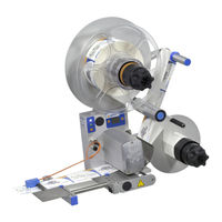
Herma 400 Operating Instructions Manual (154 pages)
Brand:
Herma
| Category:
Label Maker
| Size: 6.19 MB
Table of Contents
Table of Contents
5
Overview of the Applicator
11
General Information
15
Handling of the Documentation
15
Explanation of Symbols
15
Signal Words
15
General Designations
16
Safety
17
Important Safety Information
17
Signal Word Definitions
17
Mandatory Signs
18
Personal Protective Equipment
18
Symbols on the Applicator
19
Proper Use of the Applicator
20
Responsibility of the Operator
21
Personnel
22
Applicator Description
23
Sub-Assemblies
23
Standard Unwinder
24
Motorized Unwinder - Slim Line Version
28
Motorized Loop-Type Unwinder - Slim Line Version
34
Label Web Brake
39
Label Sensor FS03
41
Work Mode (Normal Mode)
41
Setting Mode
42
Label Sensor Optoelectronic
46
Dispensing Sytems
48
Rigid/Straight Dispensing Plates
48
Dispensing Plate, 15° Angular
49
Pivot Beak / Application Unit
50
Moving Beak
51
Transfer Systems
52
Telescope
52
Transverse Transfer System
53
Drive/Transport Roller
57
Standard Rewinder
58
Motorized Rewinder - Slim Line Version
64
Technical Data
73
Dimensions / Weight (Configuration Examples)
75
Inputs / Outputs (X10) (Option, Standard Signals)
76
Inputs / Outputs (X19) (Option, Extended Signals)
77
Transport, Installation, Storage and
79
Connection
79
Transporting the Applicator
79
Installing the Applicator
79
Storing the Applicator
82
Electrical Connection
83
Connections
84
Inserting the Label Web (Web Paths)
86
Right-Hand Applicator with Standard Dispensing Plate
86
Left-Hand Applicator with Standard Dispensing Plate
86
Right-Hand Applicator with Pivot Beak
87
Left-Hand Applicator with Pivot Beak
87
Right-Hand Applicator with Dispensing Plate with Spring-Loaded Roller, 75° Angular
88
Left-Hand Applicator with Dispensing Plate with Spring-Loaded Roller, 75° Angular
88
Winder System, Left-Hand Applicator
89
Winder System, Right-Hand Applicator
90
Winder System, Loop-Type Unwinder
91
Putting into Operation
93
Putting out of Operation
95
End-Of-Life Disposal
95
HERMA 400 Control)
97
Design (Keypad and Display)
98
Function Diagram
100
End of Reel and Diminishing Reel (Internal)
101
Overview Display Structure HERMA
102
The Display's Quick Menu
103
Format Selection (Quick Menu Parameter, Optional)
103
Start Delay Applicator (Quick Menu Parameter)
104
Stop Delay Label (Quick Menu Parameter)
104
Speed Difference between Applicator and Application Roller (029)
104
Speed of the Applicator (Quick Menu Parameter)
105
Speed of the Product (Quick Menu Parameter, Optional)
105
Conveyor Speed 152 (036)
105
Product Speed Transverse Transfer System (037)
105
Potentiometers
106
The Display's Configuration Menu
106
Menu 100 Basic Data
107
Master Enc. Transfer
107
Master Enc. Transfer Label Pos. Difference
107
Master Encoder Pulses / Revolution
107
Master Encoder Distance / Revolution
107
Master Encoder Start Compensation
107
Master Encoder Stop Compensation
108
Master Encoder Mini Loop On/Off
108
Master Encoder Mini Loop Start Delay
108
Master Encoder Mini Loop Size
108
Master Encoder Rollfed Cutter Distance
108
Master Encoder Rollfed Difference Stst Cont
108
Start Signal
108
Start Signal Mark Field 1
109
Start Signal Mark Field 2
109
Start Signal Mark Field 3
109
Start Inhibit Start Inhibit Distance
109
Multi Labelling
109
Multi Labelling Number of Labels
109
Stop Signal
110
Stop Signal Mark Field 1
110
Stop Signal Mark Field 2
110
Stop Signal Mark Field 3
110
Stop Inhibit Stop Inhibit Distance
110
Hole Inhibit Hole Inhibit Distance
110
Label Tolerance
110
Stop Sensor Label Position
111
Stop at Missing Label
111
Stop Sensor: Nolabel
111
Printer On/Off
111
Printer Every Nth Label
111
Printer Start Delay
111
Printer Print Time
112
Printer Printing Length
112
Menu 200 Transfer Data
113
Application Type
113
Pivot Beak On/Off
114
Pivot Beak Type
114
Pivot Beak Start Delay
114
Pivot Beak Activation Time
114
Pivot Beak Stop Delay
114
Roller Unit Start Delay
115
Roller Unit Stop Delay
115
Dispensing Unit Label Start Delay
116
Dispensing Unit Work Pos. Reached
116
Dispensing Unit Work Pos. Return del
116
Dispensing Unit Home Pos. Reached
116
Transfer Unit after Blow
116
Transfer Unit Work Pos. Reached
116
Transfer Unit Work Pos. Return del
116
Transfer Unit Blow
116
Transfer Unit Home Pos. Reached
116
Prism Control System
117
Outfeed Jam Running Time
117
AUTOMATIC Slow-Down Time
117
Prism Start Delay
117
Prism Stop Delay
117
Start Detection Start Delay
117
Start Detection Start Monitoring
117
Auxiliary Control System
118
268: Auxiliary Start Delay
118
269: Auxiliary Stop Delay
118
Label Check on / off
119
Label Check Aft. Feed
119
Lab. Check Aft. Transf
119
Label Check Start Delay
119
Menu 400 Format
120
Format Load
120
Format Save
120
Format Save Enter Name
120
Format Delete
120
Menu 500 Batch
121
Batch Size
121
Menu 900 System
122
Rotate Display Drehen
122
Sprache / Language
122
Ready Screen
122
Alarm Message after Missing Labels
123
Alarm Message after End of Reel
123
Alarm Message after Undefined Web Move
123
Alarm Message after Start Sequ. too Close
123
Monitoring Quality
123
Unwinder Disc
124
Diminishing Reel Diameter
124
Bluetooth
124
Bus Adress (RS485)
124
Display Add. Output
124
Serial No. Applic
124
Unwinder Oper. Modes
125
Unwinder Output
125
Loop Unwinder
126
Loop Unwinder Output
127
Unwinder Mode
128
Rewinder Mode
128
Loop Unwinder Mode
128
Rewinder Output
128
Unwinder Protection 1
129
Unwinder Protection 2
129
Bus Adress (RS485)
129
Display Add. Output
130
Cleaning, Maintenance, Service
131
Maintenance Schedule
132
Troubleshooting
133
Indication of Malfunctions
133
List of Malfunctions (Indicated Via Display)
134
SM106 Missing Label at Dispensing Beak
134
SM107 End of Label Web
134
SM108 Dispensing Unit Does Not Reach Home Position
134
SM109 Dispensing Unit Does Not Leave Home Position
134
SM110 Dispensing Unit Does Not Reach Work Position
134
SM111 Dispensing Unit Does Not Leave Work Position
134
SM113 Transfer Unit Does Not Reach Home Position
134
SM851 Winder Failure Temperature too High
140
SM854 Rewinder Failure Power Stage
140
SM865 Loop Filler Failure
140
SM910 Drive Failure Low Voltage
140
SM911 Drive Failure High Voltage
140
SM912 Drive Failure High Temperature
140
SM913 Drive Failure Overload (Period)
140
SM914 Drive Failure
140
SM916 Drive Failure
140
SM917 Drive Failure Powerfail
141
SM918 Drive Failure
141
SM919 Drive Failure Low Voltage (Peak)
141
SM920 Drive Failure Overload (Peak)
141
SM921 Drive Failure
142
SM922 Drive Failure
142
SM923 Drive Failure
142
SM924 Drive Failure Overload
142
SM925 CAN Communication Disturbed
142
SM926 Drive Failure: Overload (Vmax Exceeded!)
142
SM999 Drive Mode was Changed! F-Button = Restart
143
Malfunction Table (LED Indication)
144
Remedy of Malfunctions
145
Error Blink Codes with PLC Connection
145
Other Malfunctions
146
Replace the Drive Unit
148
Remove the Drive Unit
148
Ship the Drive Unit
150
Mount the Drive Unit
150
Technical Service
150
Spare Parts
151
A1 Index
153
Advertisement
Herma 400 Original Operating Instructions (130 pages)
Brand:
Herma
| Category:
Label Maker
| Size: 5.71 MB
Table of Contents
Table of Contents
5
Safety
11
Important Safety Precautions
11
General Safety Information
12
Transport, Installation and Connection
13
Transporting the Applicator
13
Installing the Machine
13
Electrical Connection
14
Connections
15
Area of Application
17
Intended Use of the Machine
17
Adhesive Labels
17
Inserting the Label Web
19
Label Web Insertion Schemes
19
Right-Hand Applicator with Standard Dispensing Plate
19
Left-Hand Applicator with Standard Dispensing Plate
19
Right-Hand Applicator with Pivot Beak
20
Left-Hand Applicator with Pivot Beak
20
Detailed Illustrations
20
Right-Hand Applicator with Dispensing Plate with Spring-Loaded Roller, 75° Angular
21
Left-Hand Applicator with Dispensing Plate with Spring-Loaded Roller, 75° Angular
21
Winder System, Left-Hand Applicator
22
Winder System, Right-Hand Applicator
23
Winder System, Loop-Type Unwinder
24
Commissioning and Operation
25
Operation / Settings Via the HERMA
26
Design
27
Key Pad
27
Display
29
Function Diagram
29
End of Reel and Diminishing Reel (Internal)
30
Overview Display Structure HERMA
31
The Display's Quick Menu
32
Format Selection (Quick Menu Parameter, Optional)
32
Start Delay Applicator (Quick Menu Parameter)
33
Stop Delay Label (Quick Menu Parameter)
33
Speed of the Applicator (Quick Menu Parameter)
34
Speed of the Product (Quick Menu Parameter, Optional)
34
Potentiometers
34
The Display's Configuration Menu
35
Calling up
35
Design
35
Menu 100 Basic Data
35
Master Encoder Pulses / Revolution
35
Master Encoder Distance / Revolution
36
Master Encoder Start Compensation
36
Master Encoder Stop Compensation
36
Master Encoder Mini Loop On/Off
36
Master Encoder Mini Loop Start Delay
36
Master Encoder Mini Loop Size
36
Master Enc. Transfer
36
Master Enc. Transfer Label Pos. Difference
37
Start Signal
37
Start Signal Mark Field 1
37
Start Signal Mark Field 2
37
Start Signal Mark Field 3
37
Start Inhibit Start Inhibit Distance
37
Multi Labelling
37
Multi Labelling Number of Labels
38
Stop Signal
38
Stop Signal Mark Field 1
38
Stop Signal Mark Field 2
38
Stop Signal Mark Field 3
38
Stop Inhibit Stop Inhibit Distance
38
Hole Inhibit Hole Inhibit Distance
38
Stop Sensor Label Position
39
Stop at Missing Label
39
Stop Sensor: Nolabel
39
Printer On/Off
39
Printer Every Nth Label
39
Printer Start Delay
39
Printer Print Time
39
Printer Printing Length
40
Menu 200 Transfer Data
41
Application Type
41
Pivot Beak On/Off
42
Pivot Beak Type
42
Pivot Beak Start Delay
42
Pivot Beak Activation Time
42
Pivot Beak Stop Delay
42
Roller Unit Start Delay
43
Roller Unit Stop Delay
43
Dispensing Unit Label Start Delay
44
Dispensing Unit Work Pos. Reached
44
Dispensing Unit Work Pos. Return del
44
Dispensing Unit Home Pos. Reached
44
Transfer Unit Work Pos. Reached
44
Transfer Unit Work Pos. Return del
44
Transfer Unit Blow
44
Transfer Unit Home Pos. Reached
44
Transfer Unit after Blow
44
Prism Control System
45
Outfeed Jam Running Time
45
AUTOMATIC Slow-Down Time
45
Prism Start Delay
45
Prism Stop Delay
45
Start Detection Start Delay
45
Start Detection Start Monitoring
45
Auxiliary Control System
46
268: Auxiliary Start Delay
46
269: Auxiliary Stop Delay
46
Label Check on / off
47
Label Check Aft. Feed
47
Lab. Check Aft. Transf
47
Label Check Start Delay
47
Menu 400 Format
48
Format Load
48
Format Save
48
Format Save Enter Name
48
Format Delete
48
Menu 500 Batch
49
Batch Size
49
Menu 900 System
50
Rotate Display Drehen
50
Sprache / Language
50
Ready Screen
50
Alarm Message after Missing Labels
51
Alarm Message after End of Reel
51
Alarm Message after Undefined Web Move
51
Alarm Message after Start Sequ. too Close
51
Unwinder Disc
51
Diminishing Reel Diameter
51
Bluetooth
51
Bus Adress (RS485)
52
Display Add. Output
52
Serial No. Applic
52
Unwinder Oper. Modes
52
Unwinder Output
53
Loop Unwinder
54
Loop Unwinder Output
54
Overview and Sub-Assemblies
57
Overview
57
Function
57
Sub-Assemblies
58
Standard Unwinder
59
Motorized Unwinder - Slim Line Version
63
Motorized Loop-Type Unwinder - Slim Line Version
68
Label Web Brake
72
Label Sensor FS03
74
Work Mode (Normal Mode)
74
Setting Mode
75
Label Sensor Optoelectronic
79
Dispensing Sytems
81
Rigid/Straight Dispensing Plates
81
Dispensing Plate, 15° Angular
82
Pivot Beak / Application Unit
83
Moving Beak
84
Transfer Systems
85
Telescope
85
Transverse Transfer System
86
Drive/Transport Roller
89
Backing Paper Take-Up Unit Standard
90
Motorized Rewinder - Slim Line Version
95
Troubleshooting
103
Indication of Malfunctions
103
SM919 Drive Failure Low Voltage (Peak)
109
SM920 Drive Failure Overload (Peak)
109
SM921 Drive Failure
110
SM922 Drive Failure
110
SM923 Drive Failure
110
SM924 Drive Failure Overload
110
SM925 CAN Communication Disturbed
110
SM926 Drive Failure: Overload (Vmax Exceeded!)
110
SM999 Drive Mode was Changed! F-Button = Restart
110
Malfunction Table (LED Indication)
111
Remedy of Malfunctions
112
Error Blink Codes with PLC Connection
112
Other Malfunctions
113
Replace the Drive Unit
115
Remove the Drive Unit
115
Ship the Drive Unit
117
Mount the Drive Unit
117
Technical Service
117
Cleaning, Maintenance, Service
119
Technical Data
121
Inputs / Outputs (X10) (Option, Standard Signals)
123
Inputs / Outputs (X19) (Option, Extended Signals)
124
Declaration of Incorporation
125
Spare Parts
127
A1 Index
129
Advertisement
Related Products
Herma 500
Herma Categories
Label Maker
Projection Screen
Racks & Stands
Projector Accessories
More Herma Manuals
Login
Sign In
OR
Sign in with Facebook
Sign in with Google
Upload manual
Upload from disk
Upload from URL