
Related Manuals for Herma 500


Summary of Contents for Herma 500
- Page 1 Documentation Applicator HERMA 500 > Safety > Quick Guide > Operating Instructions 625817 • 1.10 GB (2019/02/28) HERMA GmbH • Labelling Machines Division • 70791 Filderstadt • Germany...
- Page 2 info@herma.com...
-
Page 3: Table Of Contents
Documentation HERMA 500 Table of Contents Quick guide ................................... 3 Set-Up Mode ................................. 3 Important Points and FAQs ............................3 Threading the Label Web ............................. 4 Menu Navigation ................................4 Operating instructions ..............................5 ... - Page 4 Table of Contents Assemblies – General Information .......................... 22 Unwinder: Mechanical ............................. 22 Inserting the Label Web ............................22 Unwinder: Motorised ............................... 23 Inserting the Label Web ............................23 Loop Module: Motorised ............................25 Inserting the Label Web ............................
- Page 5 Documentation HERMA 500 Electrical Connection ..............................52 Connections ................................52 Connecting the Compressed Air Supply ........................54 Storage ..................................55 Start-up After Storage ..............................55 Disposal ..................................55 Start-up ..................................57 Start-up – General Information ........................... 57 ...
- Page 6 Table of Contents Save Format ............................... 79 Save Format As ............................79 Settings ................................. 79 Product ................................79 Label ................................80 Application ..............................80 Printer ................................80 Winder ................................80 Unwinder ..............................81 ...
- Page 7 Documentation HERMA 500 Other Settings ............................. 83 Alarm History .............................. 83 Imprint ................................83 Settings – retooling the product ..........................84 Settings – Retooling the Product ..........................84 Authorised Staff ............................... 84 Settings ................................85 ...
- Page 8 Table of Contents Acknowledging Malfunctions ..........................105 Message Explanation ............................106 Starting Up after a Malfunction ..........................106 Power Failure ................................107 Customer Support ..............................107 Replacement parts ..............................108 Replacement Parts ..............................108 ...
- Page 9 Documentation HERMA 500 Before using the product, read all the instructions and make sure you have understood everything. The instructions contain important information for protecting your personal safety. Anyone who works on this machine at any stage in production must have read and understood these instructions.
- Page 10 Set-Up Mode Lacking or improper maintenance Use of the product after significant wear Similar cases Observe the safety instructions in the operating instructions. Click/tap on the header or the icon for these instructions to read the entire text. Click/tap on collapse the text.
-
Page 11: Quick Guide
Documentation HERMA 500 Quick guide Set-Up Mode HERMA 500 When you start up the applicator for the first time, it is important to configure the appropriate parameters and make the necessary settings for your task. To make this process as easy for you as possible, we have provided a set-up mode that guides you through the initial settings. -
Page 12: Threading The Label Web
PC. See also the instructions on Ethernet connections in the Extended settings You can find notes on products, components, settings, replacement parts, FAQs and much more on the Internet at https://www.herma.com/machines. Threading the Label Web See the “Label Web Threading Diagram”... -
Page 13: Operating Instructions
Documentation HERMA 500 Operating instructions Translation of the original operating instructions HERMA 500 HERMA GmbH • Labelling Machines Division • 70791 Filderstadt • Germany 1.10 GB (2019/02/28) -
Page 14: Introduction
No part of this documentation may be reproduced, nor may it be processed, duplicated or distributed using electronic systems, without the advance written consent of HERMA GmbH, except for use within the company. 1.10 GB (2019/02/28) -
Page 15: Applicator Overview
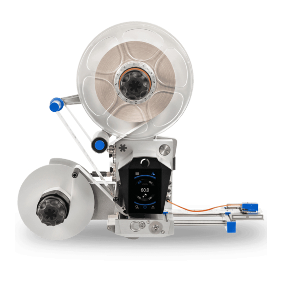
Documentation HERMA 500 Applicator Overview Unwinder (mechanical unwinder shown here; motorised unwinder also possible) Counterholder (only required for vertical applicators) Rewinder (mechanical rewinder shown here; motorised rewinder also possible) Dispense button above the display (in the rest of these instructions and during... -
Page 16: General Information
Applicability General information Applicability These operating instructions apply to the following machine: Applicator: HERMA 500 (the “product”) Manufacturer: HERMA GmbH 70791 Filderstadt Germany – Labelling Machines Division – Phone: +49 (0)711 / 7702 0 Fax: +49 (0)711 / 7702 700 https://www.herma.com... -
Page 17: Handling Of The Documentation
Documentation HERMA 500 Version: 1.10 EN_GB Year of manufacture: See nameplate Handling of the Documentation The operating instructions must be available to all personnel working on the machine at all times. The operator must ensure that personnel who operate or maintain the system have read and understood all safety instructions, precautionary measures, prohibited behaviour and comments contained in these operating instructions. -
Page 18: Structure Of The Documentation
2. Operating instructions for the machine (this document). Integrated in the applicator, available separately for download in our service portal: https://www.herma.com/machines. 3. Wiring diagram in paper form, available separately for download in our service portal: https://www.herma.com/machines. -
Page 19: Safety
Documentation HERMA 500 Safety Safety Instructions Click/tap on the header or the icon for these instructions to read the entire text. Click/tap on collapse the text. Important safety precautions Servicing the machine may require you to enter unprotected areas. Switch off the power supply before maintaining or cleaning the machine. - Page 20 Safety Instructions General safety instructions If protective equipment is not working and fundamental processes are not observed, the operating staff’s safety cannot be ensured. For this reason, observe the following: Before starting the machine for the first time, ensure that the protective equipment is functioning properly. Check again before each time you start work on the machine.
-
Page 21: Signal Words: Definitions
Documentation HERMA 500 Signal Words: Definitions Identifies a hazard that, if not avoided, will result in death or serious injuries. Identifies a hazard that, if not avoided, could result in death or serious injuries. Identifies a hazard that, if not avoided, could result in moderate or minor injuries. -
Page 22: Intended Use Of The Machine
Make sure to wear safety gloves. Intended Use of the Machine The HERMA 500 applicator is an electronically controlled device that is used to apply different adhesive labels to a wide variety of products. You can use the applicator to unwind label reels, detect and dispense labels from the backing paper and then roll up the backing paper. -
Page 23: Machine Users
Only trained staff may use the machine. The staff must be trained by the manufacturer HERMA GmbH or a HERMA partner. The operator can provide the training if they are sufficiently qualified to do so, e.g. they studied these instructions carefully and have experience with industrial applications and the hazards that can result. -
Page 24: User 1
Intended Use of the Machine working conditions at the installation location. These regulations and information must be implemented as work instructions for operating the product. Throughout the product’s entire service life, the operator must check whether the work instructions created are in line with the current versions of the regulations, and adjust the work instructions as necessary. -
Page 25: What To Do In An Emergency
Documentation HERMA 500 What to Do in an Emergency Turn off the machine using the main switch and disconnect the mains plug. Follow your company’s or organisation’s instructions for handling emergencies. Measures in Case of Fire Turn off the machine using the main switch and disconnect the mains plug. Only use CO2 fire extinguishers or fire extinguishers of class ABC to put out the fire. -
Page 26: Safety Equipment
Measures in Case of Fire Safety equipment Safety Equipment The following safety equipment is provided, not including any customer-provided devices, e.g. a special cover for the controller on the base unit. – Clamping plate guard – Counterholder Clamping Plate Guard Do not modify or remove! This device must not be modified or removed. - Page 27 Documentation HERMA 500 The counterholder 2 prevents the label reel from falling when the applicator is vertically installed. Make sure to clamp the label reel and the counterholder in place. See the “Unwinder: Mechanical” section. 1.10 GB (2019/02/28)
-
Page 28: Description Of The Applicator
Description of the applicator Description of the Applicator The HERMA 500 applicator is an electronically controlled device that is used to apply different adhesive labels to a wide variety of products. You can use the applicator to unwind label reels, dispense labels from the backing paper and then roll up the backing paper. -
Page 29: Function
Documentation HERMA 500 Function The applicator intermittently dispenses from the backing paper one label after another at the dispensing plate. The label web is transferred by a mating roller that is driven by a servo motor. The applicator controller is integrated into the base unit. -
Page 30: Assemblies
Function Assemblies Assemblies – General Information Most assemblies are available in different variants. For example, the unwinder is available in a standard design (mechanically controlled) or a motorised variant, the backing paper take-up unit can be mechanical or motorised, the sensor can be an FS03 or a forked light barrier, etc. Please see the pictures and illustrations in the various sections for the particular variants used in your applicator. -
Page 31: Unwinder: Motorised
Documentation HERMA 500 “Settings – Retooling the Product” section describes the settings you can make on this unit. Unwinder: Motorised Possible hazard at pendulum If hazard areas arise during operation as a result of the pendulum, you must secure these areas appropriately. - Page 32 Function Function of the illuminated button The illuminated button a has multiple functions: Switch the unit on/off Change the direction of rotation Teach in the angle sensor (see the “Settings – Retooling the Product” section) Set to smooth mode (see the “Settings –...
-
Page 33: Loop Module: Motorised
Documentation HERMA 500 Error codes Error codes, i.e. flashing codes, can be acknowledged and reset by briefly pressing the illuminated button. The following codes are possible: Flashes Cause Measurement error during teach-in of the angle sensor (see “Teaching in the Angle Sensor (Motorised Unwinder)”) - Page 34 Function Guide the label web to the drive roller b. Make sure that the two sensors c for loop control are not covered. Press the illuminated button a. The button will flash rapidly. Press the plate d downwards, which causes the label web to be pressed against the drive roller and transported to the loop module.
-
Page 35: Label Web Brake
Documentation HERMA 500 Time the button is Action/Function pressed 1. Switches on the unit if it is currently switched off. < 3s 2. Resets the unit if an error is pending (indicated by flashing code, see below). > 3s and < 10s Switch the unit off “Settings –... -
Page 36: Inserting The Label Web
Function Inserting the Label Web Grab the brake plate by the black knob and pull it to the side to swing it out of the way. Slide the label web under the brake plate. Return the brake plate to the original position and press it until it locks into place. Adjusting the Braking Force The braking force has been preset at the factory and only needs to be adjusted if needed. -
Page 37: Label Sensor: Fs03
Documentation HERMA 500 Label Sensor: FS03 1 – LED 2 – Set button The material number of the label sensor with plug is printed on the housing. The FS03 label sensor is a self-learning unit, suitable for paper labels as well as electrically conductive labels (metalised or aluminium covered). - Page 38 Function Depending on the application, the label either has to be completely detached (when using suction), or it must remain briefly attached to the backing paper (if it is to be pulled off), or it must protrude only slightly (for labelling products in motion).
- Page 39 Documentation HERMA 500 If the teaching was not successful, the procedure must be repeated. Make sure that the sensor is positioned in the gap between the labels and the subsurface is clean (no adhesive residues or the like). > 10s, < 15s LED flashes, setting the type of label (paper or metal).
-
Page 40: Label Sensor: Optoelectronic
2 – LED The optoelectronic label sensor of the HERMA 500 unit is used for contact-free detection of non-transparent labels on any backing paper. The unit is set up so that label gaps can be quickly identified with extreme precision. -
Page 41: Positioning The Label
Documentation HERMA 500 Positioning the label Depending on the application, the label either has to be completely detached (when using suction), or it must remain briefly attached to the backing paper (if it is to be pulled off), or it must protrude only slightly (for labelling products in motion). -
Page 42: Dispensing Systems
Function Dispensing Systems Dispensing beaks The following dispensing beak designs are available: Simple dispensing plate Dispensing beak with roller Dispensing beak with spring-loaded roller Dispensing beak with brush 15° angled dispensing beak NOTICE: For all dispensing systems, make sure that the label web is fed in a straight line (touching the paper guides). -
Page 43: Moving Dispensing Beak
Documentation HERMA 500 Inserting the Label Web Insert the label web according to the diagram shown here. Moving dispensing beak Risk of crushing! The pneumatic operating pressure must not exceed 5 bar. Risk of crushing! Inserting the label web Insert the label web according to the diagram shown here. -
Page 44: Transfer Systems
Function Transfer Systems Depending on the application, one of a range of different telescoping units (linear units) may be installed in your machine. These units require no maintenance. Observe the following: Risk of crushing! The pneumatic operating pressure must not exceed 5 bar. Risk of crushing! Positioning the Label on the Suction Plate The label must be positioned in the centre of the suction plate. -
Page 45: Inserting The Backing Paper
Documentation HERMA 500 Inserting the Backing Paper Open the clamping plate on the blue transport roller by pressing the plate downwards. Push hard enough to overcome the resistance until the black application roller is free. Slide the backing paper from below between the transport roller and the application roller and place it against the wall of the housing. -
Page 46: Rewinder: Mechanical
Function You can change the contact pressure of the clamping plate by choosing different stop positions. To do so, screw the provided screw into the other hole. The lower position provides the higher contact pressure (see figure). Be sure to insert the screw in the same position on both ends of the plate. NOTICE: The clamping plate and the application roller can be easily removed and reinstalled for cleaning. -
Page 47: Rewinder: Motorised
Documentation HERMA 500 “Settings – Retooling the Product” section describes the settings you can make on this unit. Rewinder: Motorised Inserting the Label Web Insert the label web according to the diagram below. Switch the unit on and off using the switch / illuminated button a. - Page 48 Function Function of the illuminated button The illuminated button a has multiple functions: Switch the unit on/off Teach in the angle sensor (see the “Settings – Retooling the Product” section) Indicate errors using flashing codes See the tables below NOTICE: The unit is READY (switched on) as soon as the voltage is applied and the illuminated button will light up.
- Page 49 Documentation HERMA 500 Caution: rotation Please note that the rewinder will begin to rotate as soon as the voltage is applied if no backing paper is inserted at this moment. This rotation will stop automatically after a short time. Time the button is...
-
Page 50: Technical Data
Technical data Technical data Technical data The HERMA 500 applicators leave our factory with tested functionality and are ready for operation with default settings. The following specifications refer to the applicator’s drive unit. Model versions “IO” for I/O applicators, “IE” for industrial Ethernet applicators. (See the type plate of the basic unit.) - Page 51 Documentation HERMA 500 Recommended external fusing (“HERMA 500” = applicator only, “winder” = HERMA 500 + up to 3 winder units) 220V AC, HERMA 500: 5A slow acting 220V AC, winder: 10A slow acting 110V AC, HERMA 500: 10A slow acting...
- Page 52 I; Class 2 peripheral devices may be connected Label roll diameter Standard: 300mm • 12" Optional: 400 / 500 / 600mm • 16 / 20 / 23.6"; 600mm only with motorised winder) Core diameter Standard: 76mm • 3" Winding diameter for mechanical rewinder 210mm / 290mm •...
- Page 53 Documentation HERMA 500 Distance between labels 2 – 3mm • 0.08 – 0.11" Design variants For right-handed and left-handed operation, arranged vertically (V) or horizontally (H). (See the type plate of the basic unit / the component in question.) Dimensions...
-
Page 54: Inputs/Outputs (X10), Standard Signals
Inputs/Outputs (X10), Standard Signals When connecting the applicator to an external controller there are connectors available for inputs and outputs. For the assignment of these optional connectors see the following sections. Unused outputs must be insulated before the unit is started up. Inputs/Outputs (X10), Standard Signals This optional connection provides inputs/outputs for external control (e.g. -
Page 55: Inputs/Outputs (X19), Additional Signals
Documentation HERMA 500 Inputs/Outputs (X19), Additional Signals This optional connection provides inputs/outputs for external control (e.g. PLC). Designation || I/O || Description || Colour || On circuit board 70039292 +24V || Out || Voltage supply (< 150 mA) || Brown || X39.1 Gnd || I/O || Earth (all DC voltages) || Blue || X39.2... - Page 56 Inputs/Outputs (X9), Industrial Ethernet Lock || In || Lock applicator start (1 – active) || Red || X39.9 No_Label || Out || Label missing on backing paper || Purple || X39.10 Feeding || Out || Label transfer under way || Grey-pink || X39.11 Ready || Out || Applicator ready || Red-blue || X39.12 1.10 GB (2019/02/28)
-
Page 57: Transport, Installation, Connection, Storage And Disposal
Trained electrician – for work on the electrical system Network security must be at a correspondingly high level. The HERMA 500 applicator must be part of a secure network with limited access. If the applicator is connected to the Internet, we recommend strict use of a VPN or HTTPS channel. -
Page 58: Installing The Applicator
Remove the label reel when transporting the applicator Remove the label reel when transporting the applicator. Installing the Applicator If you notice any damage caused by transport while removing the machine’s packaging, notify your HERMA sales centre immediately. Use assembly aids Heavy objects could tilt or fall over, and are difficult to move without appropriate aids. - Page 59 Documentation HERMA 500 The applicator may not be used in explosive atmospheres. Properly mount the applicator before power is applied. Installation/removal may only be performed by trained specialists when the applicator is disconnected from the power supply. Properly mount the applicator and put the protective covers back on before applying power.
-
Page 60: Electrical Connection
Disconnect the applicator from the mains before working on the parts of the electrical equipment. After you disconnect the HERMA 500 applicator from the mains, wait at least five minutes before opening the housing or touching the connection pins. RESIDUAL VOLTAGES! Properly mount the applicator before power is applied. - Page 61 Documentation HERMA 500 Connections on the side of the housing Master encoder IO and IE Industrial Ethernet (fieldbus), in conjunction with Industrial Ethernet (fieldbus), in conjunction with Standard I/O signals Additional I/O signals Power IN IO and IE Web (Ethernet TCP / IP)
-
Page 62: Connecting The Compressed Air Supply
Connecting the Compressed Air Supply For a motorised unwinder, the signals for end of reel and diminishing reel can only be detected simultaneously if the unwinder is connected via CAN bus (X18). These reel signals are detected automatically. For the pin assignments of the connections, please refer to the Technical Data or the separate wiring diagram. -
Page 63: Storage
Documentation HERMA 500 Connect the applicator to the compressed air supply. If applicable, activate the pneumatic system of the machine by setting the valve accordingly. Representative photo Storage Observe the following to ensure that applicators that will not be in use for a longer period of time will still function properly: ... - Page 64 Disposal In particular, ensure that substances that could contaminate groundwater, e.g. greases, oils, coolants and cleaning fluids that contain solvents, do not get into the soil or sewer system. These substances must be collected, stored, transported and disposed of in suitable containers. ...
-
Page 65: Start-Up
Documentation HERMA 500 Start-up Start-up – General Information Authorised staff User 1 – for turning on the machine and starting production User 2 – for loading the appropriate format Remove products If products are in the machine when it is turned on, the products could move in an uncontrolled manner. -
Page 66: Label Web Threading Diagram
Label Web Threading Diagram This switch is a disconnector switch that isolates the applicator from the mains in case of a malfunction. Tap the power button on the applicator display. The colour switches from white to blue. Manually dispense two to three labels using the dispense button to check that the unit is working correctly. -
Page 67: Winder System
Documentation HERMA 500 Right-hand orientation Left-hand orientation Winder System Beyond these standard configurations, further distinctions are made between versions that employ a winder system (motorised unwinder and backing paper take-up unit, with or without loop module). These configurations, including the label path, are shown in the figures below. - Page 68 Label Web Threading Diagram Left-hand unwinder version with single/double pendulum Right-hand unwinder version with single/double pendulum 1.10 GB (2019/02/28)
- Page 69 Documentation HERMA 500 Left-hand/right-hand loop module version Type 4 Type 5 Type 7 1.10 GB (2019/02/28)
-
Page 70: Shutting Down
Shutting Down – General Information Shutting down Shutting Down – General Information Authorised Staff User 1 – for stopping production and turning off the machine Tap the on/off button for operation mode on the applicator display. The colour switches from blue to white. -
Page 71: Operation Using The Control Program
Operation Using the Control Program A touchscreen is integrated in the HERMA 500. Scroll through the screen vertically using a swiping motion (similar to the swiping motion on smartphones) and open a function or parameter by lightly tapping on the icon or area. If there is no immediate response, tap again using either more or less pressure. -
Page 72: Start Screen (Operation Mode On)
Operation Using the Control Program User/login menu, also displays the current password level. Direct selection / quick access to a parameter using its number. Switch on operation mode. Show past messages (message history) Start Screen (Operation Mode On) Once operation is switched on using button 4, the screen looks as follows: Start screen parameters for quick access to frequently used parameters (favourites). -
Page 73: Login
Tap this button to log into the control program using the correct password for the job/application. The current password level is displayed once you have logged in (here: level 3). Note: Passwords for the HERMA 500 applicator consist only of digits, like a PIN. Password levels Passwords are assigned to various levels. -
Page 74: Menu Navigation And Structure
Menu Navigation and Structure Menu Navigation and Structure The following menus appear after you tap the menu button: Help Open quick overview, operating instructions, FAQs. Format Create and access formats. 1.10 GB (2019/02/28) - Page 75 Documentation HERMA 500 Settings Make general, mostly one-time settings for the control program, e.g. the display language. Product Make product-specific settings, e.g. start delay, master encoder, etc. Label Make label-specific settings, e.g. stop delay, applicator speed, etc. Application Make application-specific settings, e.g. selecting the application type, parameterising dispensing systems, etc.
-
Page 76: Icons
Icons Imprint Access device-specific information, e.g. the device ID, software versions, etc. See the section of the same name in “Operating Menus”. Icons The following table contains all the icons/symbols used on the applicator display. Help menu Format menu Settings Product menu Labels menu Application menu... - Page 77 Documentation HERMA 500 Open menu User menu Indicates authorisation (password level) of current user Direct selection Switch operation mode on/off Remote activation/deactivation Show past messages (message history) Product speed Applicator speed Loop module Batch Batch counter Remainder counter Performance Start delay...
- Page 78 Icons Assign user parameters Positive/negative (toggle) Enter values: plus (increase value) / minus (decrease value) / point (decimal separator) Go back one step/screen Open information Set-up mode User/password Enable functions Firmware update (only via Ethernet) Device backup and restore (only via Ethernet) Industrial Ethernet menu (fieldbus menu) OPC menu Simulation...
-
Page 79: Start Screen Parameters For Quick Access (Favourites)
Documentation HERMA 500 Representation of the dispense button above the display in these instructions and during Ethernet-based remote operation of the applicator Additional icons are listed below within the descriptions of their corresponding menus. Start Screen Parameters for Quick Access (Favourites) Parameters 51 through 54 in the “Extended settings”... -
Page 80: Direct Parameter Access
Direct Parameter Access Direct Parameter Access You can access the parameters for the control program by browsing through the individual menus. If you already know the number of the parameter, you can access it quickly by pressing the direct selection button on the start screen and entering the number. - Page 81 Documentation HERMA 500 1.10 GB (2019/02/28)
-
Page 82: Opening And Editing Parameters
Opening and Editing Parameters Opening and Editing Parameters When you select a menu from the menu list, a list of available parameters is displayed (the “Settings” menu this example): Tap a number or name to change the value of this parameter. There are two basic types of parameter: selection parameters, which have values that are selected from a list, and input parameters, which have a value that can be freely edited. -
Page 83: Selection Parameters
Documentation HERMA 500 Tap this icon (displayed for password level 3 and higher) to specify whether this parameter is displayed for users. Selection Parameters Tap a value in the list to select it (Rigid Beak in this example) and then confirm the selection with... -
Page 84: Input Parameters
Opening and Editing Parameters Input Parameters Enter the desired value directly using the virtual keyboard or use the buttons to increase (1) or decrease (2) it. Values 3 and 4 indicate the permitted range (from ... to) for this parameter. The following buttons are also available: Change the sign Enter a decimal separator... - Page 85 Documentation HERMA 500 See the “Start Screen Parameters for Quick Access” section to learn how to save frequently used parameters (as favourites) for quick access on the start screen. 1.10 GB (2019/02/28)
-
Page 86: Operating Menus
(FAQs). The complete operating instructions for this applicator (which you are currently reading). An enhanced operating manual with various graphics and additional information can be found in the service portal at https://www.herma.com/machines. Operating Instructions Format Create and access formats. -
Page 87: Format List
Documentation HERMA 500 This menu provides a list of the available formats, which you can select and load to the primary memory by tapping on them. You can also save new formats (the currently configured values) in new or existing storage locations. - Page 88 Opening and Editing Parameters Label Make label-specific settings, e.g. stop delay, applicator speed, etc. NOTICE: You can see an explanation for a parameter by tapping on the parameter text and then on the icon on the display. For parameters that require additional explanation, these explanations can be found in the corresponding sections of the manual.
- Page 89 It contains the following submenus: Set-Up Mode This mode leads you through all the parameters that are necessary to operate the HERMA 500. This ensures that the parameters are selected according to your requirements. Starting with general prompts about language, display alignment and others, the system then leads you through all other necessary parameters according to the information you entered and allows you to make adjustments.
- Page 90 PC or laptop. The menu items for software/firmware can be found under the “Start-up” menu item. The menu items are named “Register HERMA 500 basic unit” or “Your HERMA 500 basic units”. Make sure that you are logged in on the applicator or in your browser with sufficient authorisations.
-
Page 91: Other Settings
Password level 4 and higher. A list of the approx. 100 most recent messages on the applicator. Imprint This menu lets you access device-specific information, e.g. the device ID, software versions, etc. Further information about the manufacturer of the HERMA 500 can be found in the “Applicability” section. 1.10 GB (2019/02/28) -
Page 92: Settings - Retooling The Product
Failure to comply with these instructions could result in injuries. Using formats is a good option for switching the HERMA 500 applicator from one product to a different one. Formats allow you to make the necessary settings in the program quickly and easily. See the “Format” operating menu. -
Page 93: Settings
Documentation HERMA 500 Settings Adjusting the Label Web Path Insert the label web so that it touches the leading edge (e.g. housing or screw) along its entire path. Additionally, set the paper guides so that the label web is fixed on both sides. The paper guides should be neither too tight nor too loose. -
Page 94: Replacing The Proximity Switch (Unwinder)
Settings – Retooling the Product To test the braking point, insert a label reel and rotate the unwinder’s disc until it will no longer turn, i.e. until the brake is open. Then release the disc. The disc will be braked and you can observe the braking point based on the position of the pendulum rod. -
Page 95: Replacing The Handle (Unwinder/Rewinder)
Documentation HERMA 500 Replacing the Handle (Unwinder/Rewinder) If, after a long period of use, the handle ceases to reliably operate the roll clamp, replace the worn handle while observing the following: Turn the handle all the way to the left (maximum of five steps) to open the clamp and provide access to the fastening screw 10. -
Page 96: Teaching In The Angle Sensor (Motorised Unwinder/Rewinder)
Settings – Retooling the Product When reassembling the unit in reverse order with new tension rings, make sure that the screws are positioned exactly on the intended surfaces 17. Once the unit is completely assembled, the screws must be arranged in a line. Important: The pins (three per plug-in piece) are essential for proper functioning of the unit. -
Page 97: Activating Smooth Mode (Motorised Unwinder)
Documentation HERMA 500 Activating Smooth Mode (Motorised Unwinder) For certain applications, the winder (in this example, the motorised winder) is too dynamic in its movements. It is therefore possible to set the winder to run more “smoothly”, to start and stop less abruptly. Proceed as follows to set to smooth mode: ... - Page 98 Settings – Retooling the Product Switches 3 and 4 Determine the size of the unit (Ø of holding disc) On – On: 600mm On – Off: 400mm (select this setting on the magazine filler) Off – On: 500mm Off – Off: 300mm (select this setting on the loop module) Switches 5 and 6 Determine the unit’s core diameter On –...
-
Page 99: Fs03 Sensor
Documentation HERMA 500 Off: Anticlockwise (choose this setting on the unwinder/winder in version L, on the loop module and the magazine filler in version R) If you change the rewinder’s direction of rotation using DIP switch 8, the change does not take effect until you teach in the angle sensor again (see “Teaching in the angle sensor (motorised... -
Page 100: Replacing The Sensor Head
Settings – Retooling the Product 2mm • 0.08" 40m/min • 1,600"/min, <= 120m/min • 4,700"/min Min. 2.5mm • 0.1" 120m/min • 4,700"/min Min. 3.0mm • 0.12" Replacing the Sensor Head Unscrew the screw 4 to replace the sensor head 3. The sensor needs to be readjusted after you replace the sensor head (see “Setting Mode”... -
Page 101: Connection Diagram
Documentation HERMA 500 max. 20mA utput voltage low/high: 2.5V / >= V - 3.5V Temperature (operation/storage): 0 – 50 C / -20 – +80°C • 32 – 122 F / -4 – +176°F Degree of protection: IP 20 Protection class:... - Page 102 Settings – Retooling the Product Release the set button. During the teach-in process, the switch output is frozen on the last valid status before teach-in. Transport the label web with a maximum speed of 20m/min through the sensor so that at least 3 to 7 labels pass by the sensor.
-
Page 103: Cleaning, Maintenance, Service
When the machine is switched off for maintenance and servicing, ensure that the main switch cannot be switched back on without authorisation. After you disconnect the HERMA 500 applicator from the mains, wait at least five minutes before opening the housing or touching the connection pins. -
Page 104: Cleaning
Cleaning Cleaning Observe the safety instructions in the Cleaning, Maintenance, Service section! Clean the applicator at regular intervals. See the maintenance schedule for the intervals and the components to be cleaned. You will find information on the individual assemblies in the sections below: Label Web Brake The brake plate can be completely removed. -
Page 105: Moving Dispensing Beak
Documentation HERMA 500 Moving Dispensing Beak To clean the guide rollers, simply pull them out. When reinstalling them, note that the rollers will give noticeable resistance when you are pushing them back on. Drive/Transport Roller The clamping plate can be completely removed. Proceed as follows: Press the clamping plate down to open it. - Page 106 Maintenance Schedule Recommended interval // Maintenance task Daily Dispensing system / transfer system Remove any adhesive residue and clean the unit. Applicator transport roller Remove any adhesive residue and clean the unit. See also the operating instructions for the applicator. Applicator brake plate Remove any adhesive residue and clean the unit.
- Page 107 Documentation HERMA 500 Every 10 years Replace all pneumatic lines (if applicable). General, depending on intensity of use The toothed belt in the base unit of the applicator and the belt for the backing paper take-up unit will require replacement after approx. 50,000,000 to 100,000,000 labelling cycles.
-
Page 108: Service And Customer Support
– available 24/7 and from anywhere in the world. Whether you have questions about your order or need help because your applicator is not working, the HERMA service portal provides you with a single platform for all your concerns. You only need to request access once and then you have access to the portal as well as to our integrated online shop for replacement parts (formerly HERMA Components). -
Page 109: Malfunctions And Troubleshooting
Documentation HERMA 500 Malfunctions and troubleshooting Malfunctions and Troubleshooting Authorised Staff User 2 – for general activities and non-critical settings Technician – for more advanced parameter settings and mechanical settings Specialist – for replacing components Observe the information in the “What to Do in an... - Page 110 Malfunctions and Troubleshooting Label web inserted incorrectly. => Insert label web according to the description of the particular component. Application roller disengaged. => Lock application roller into place. Toothed belt faulty. => Replace toothed belt. Label web passes through continuously ...
-
Page 111: Troubleshooting
Indication of Malfunctions The HERMA 500 applicator shows the type of malfunction on the display directly on the applicator. In case of error messages, the display turns red and the number of the error message (11) is displayed. The error message text is displayed below the number. - Page 112 Troubleshooting 1.10 GB (2019/02/28)
-
Page 113: Acknowledging Malfunctions
Documentation HERMA 500 Acknowledging Malfunctions If the applicator is connected to a higher-level controller, errors can often be acknowledged from a central location (e.g. on a touchscreen). Always dispense at least two labels (pressing the dispense button ) after occurrence of a malfunction in order to ensure that a label is correctly positioned at the dispensing beak. -
Page 114: Message Explanation
Starting Up after a Malfunction Message Explanation If an error message is pending, tap the info button or, if the message list is open, directly on the message to see an explanation of the displayed message. The confirm button is also displayed here for acknowledging the message. Starting Up after a Malfunction 1. -
Page 115: Power Failure
Documentation HERMA 500 Power Failure After a power failure, the machine may be in an undefined state. Always observe the following to ensure that production is resumed without any problems: 1. When the power comes back on, proceed as described in the “Start-up” chapter. -
Page 116: Replacement Parts
Order replacement parts for the HERMA 500 applicator at your convenience in the HERMA Online Shop: https://www.herma.com/machines Exploded View Drawings Exploded view drawings for the assemblies of the HERMA 500 can be found in a separate document. Visit our service portal at https://www.herma.com/machines. 1.10 GB (2019/02/28) -
Page 117: Ce Declarations
EC electromagnetic compatibility directive 2014/30/EU IEC 60947-5-2:2007 (low-voltage switching devices, control units and switching elements – proximity switches) 20/04/2016 Managing Director RoHS Directive The HERMA 500 applicator complies with the requirements laid out in the RoHS Directive 2011/65/EU. 1.10 GB (2019/02/28) -
Page 119: Glossary
Format: A set of parameters for processing a specific product. Saving and reusing formats allows you to set all necessary parameters and their values with a single click. FS03: A label sensor developed by HERMA that is also suitable for transparent labels. HMI: Abbreviation for “human machine interface”. Refers to a display, e.g. the touchscreen used in the HERMA 500. - Page 120 CE Declarations Password level: The authorisation level. Password levels can be used to assign different authorisations, i.e. access to parameters and functions, to a user. Radio menu: A menu in which exactly one option can be selected from multiple options by way of radio buttons (small, round selection fields).
-
Page 121: Index
Documentation HERMA 500 Index Disposing of the applicator 49, 55 A Drive roller 36 Acknowledging errors 103 Adhesive labels 20 E Adjusting the label web path 85 Electrical connection 51 Adjusting the web path 85 Electrical voltage 13 Angle sensor 88... - Page 122 Label winding 20 Replacing the end of reel proximity switch in unwinder 86 Levels for passwords 65 Replacing the unwinder/rewinder handle 87 Linear unit 35 Rewinder, motorised 39 Logging in to the applicator 57 Rewinder, standard 38 Logging in to the control program 65 Risk of being drawn in 13 Loop module, motorised 25 RoHS 109...
- Page 123 Documentation HERMA 500 Update of the firmware 81 Winder, activating normal mode 23 Upgrading your applicator’s functions 99 Winder, activating smooth mode 23 Winding the labels 20 V Workflow-based set-up process 3 Voltage, hazardous 13 W Web brake 27, 95...
- Page 124 1.10 GB (2019/02/28)
Need help?
Do you have a question about the 500 and is the answer not in the manual?
Questions and answers