
Related Manuals for Herma 400


Summary of Contents for Herma 400
- Page 1 Translation of the original operating instructions HERMA 400 Hier und in Kapitel 10 Geräteschild aufkleben! HERMA GmbH · Geschäftsbereich Maschinen · Plochinger Str. 48 · D-73779 Deizisau · Germany...
- Page 2 Except for internal use, including integration in the customer‘s documentation, no part of this documentation may be reproduced or processed, copied, or distributed with the help of electronic systems in any form without prior written permission of HERMA GmbH. Version 3.26 EN (200416)...
- Page 3 Translation of the original operating instructions HERMA 400 ONVENTIONS Conventions Elements of the HERMA 400 control are designated and depicted in these instructions as follows: Switch-on key Manual feed key Function key LED (on) LED (blinks) LED (off) Minus key...
- Page 4 Translation of the original operating instructions HERMA 400 ONVENTIONS www.herma.com www.herma-components.com info@herma.com 4/130 3.26 EN (200416)
-
Page 5: Table Of Contents
Translation of the original operating instructions HERMA 400 ABLE OF ONTENTS Table of Contents Safety 11 Important Safety Precautions 11 General safety information 12 Transport, installation and connection 13 Transporting the applicator 13 Installing the machine 13 Electrical connection 14 2.3.1... - Page 6 Translation of the original operating instructions HERMA 400 ABLE OF ONTENTS 5.5.3 Menu 100 Basic data 35 5.5.3.1 120 Master encoder Pulses / revolution 35 5.5.3.2 121 Master encoder Distance / revolution 36 5.5.3.3 122 Master encoder Start compensation 36 5.5.3.4...
- Page 7 284 Label check aft. feed 47 5.5.4.30 285 Lab. check aft. transf. 47 5.5.4.31 286 Label check start delay 47 5.5.5 Menu 400 Format 48 5.5.5.1 410 Format load 48 5.5.5.2 420 Format save 48 5.5.5.3 422 Format save Enter name 48 5.5.5.4...
- Page 8 Translation of the original operating instructions HERMA 400 ABLE OF ONTENTS 7.1.1 List of malfunctions (indicated via display) 104 7.1.1.1 SM106 Missing label at dispensing beak 104 7.1.1.2 SM107 End of label web 104 7.1.1.3 SM108 Dispensing unit does not reach home position 104 7.1.1.4...
- Page 9 Translation of the original operating instructions HERMA 400 ABLE OF ONTENTS 7.1.1.59 SM919 Drive failure Low voltage (peak) 109 7.1.1.60 SM920 Drive failure Overload (peak) 109 7.1.1.61 SM921 Drive failure 110 7.1.1.62 SM922 Drive failure 110 7.1.1.63 SM923 Drive failure 110 7.1.1.64...
- Page 10 Translation of the original operating instructions HERMA 400 ABLE OF ONTENTS www.herma.com www.herma-components.com info@herma.com 10/130 3.26 EN (200416)
-
Page 11: Safety
Safety Important Safety Precautions ❏ The applicator may not be used in explosive atmospheres. WARNING ❏ Mount the applicator appropriately upstream of the energy input. ❏ The applicator/machine must have a mains disconnection device to cut off the mains supply in case of malfunction. ❏... -
Page 12: General Safety Information
1 Translation of the original operating instructions HERMA 400 AFETY General safety information ❏ Before commissioning, ensure that the protective equipment WARNING is functioning properly. ❏ Check that the protective equipment is functioning properly every time before starting work on the applicator. -
Page 13: Transport, Installation And Connection
❏ Remove the roll of labels when transporting the applicator. CAUTION Installing the machine If you should notice damage due to transport when you unpack the machine inform your HERMA sales office immediately. ❏ The applicator may not be used in explosive atmospheres. -
Page 14: Electrical Connection
2 Translation of the original operating instructions HERMA 400 RANSPORT INSTALLATION AND CONNECTION Mount the applicator using the two mounting holes for round rods (2), Ø 30 mm, hole spacing: 182 mm. Secure the mounting system appropriately on the rods, e.g. using a locking screw (3), a washer (4) or the optional fine-adjustment device (5). -
Page 15: Connections
2 Translation of the original operating instructions HERMA 400 RANSPORT INSTALLATION AND CONNECTION 2.3.1 Connections The following connections are available at the HERMA 400 applicator (depending on the configuration): X14 ( ) /(X16 (special) † X13 (all types) X16 ( ) /... - Page 16 2 Translation of the original operating instructions HERMA 400 RANSPORT INSTALLATION AND CONNECTION ❏ For the appropriate pin assignment of the connections, please NOTICE refer to the section 9 or the separate wiring diagram 823299. ❏ All plugs are secured with coupling rings. Do not tilt the coupling rings when screwing it onto the socket because this could damage the thread or render it unusable.
-
Page 17: Area Of Application
Area of application Intended use of the machine HERMA 400 applicator is an electronically-controlled device that is to be used to apply different adhesive labels to a wide variety of products. You can use the applicator to unwind label rolls, dispense labels from the backing paper and then roll up the backing material. - Page 18 3 Translation of the original operating instructions HERMA 400 REA OF APPLICATION www.herma.com www.herma-components.com info@herma.com 18/130 3.26 EN (200416)
-
Page 19: Inserting The Label Web
Inserting the label web Label web insertion schemes The following schemes show how to insert the label web with the most common standard applicators. A separate insertion scheme is provided for applicator configurations other than shown here . As the case may be, this scheme may also be attached to the machine. -
Page 20: Right-Hand Applicator With Pivot Beak
4 Translation of the original operating instructions HERMA 400 NSERTING THE LABEL WEB 4.1.3 Right-hand applicator with pivot beak 681299 681299 0 = Außenwicklung / outside winding O = Außenwicklung / outside winding I = Innenwicklung / inside winding I = Innenwicklung / inside winding 4.1.4... -
Page 21: Right-Hand Applicator With Dispensing Plate With Spring-Loaded Roller, 75° Angular
4 Translation of the original operating instructions HERMA 400 NSERTING THE LABEL WEB 4.1.5 Right-hand applicator with dispensing plate with spring-loaded roller, 75° angu- 681300 681300 0 = Außenwicklung / outside winding O = Außenwicklung / outside winding I = Innenwicklung / inside winding I = Innenwicklung / inside winding 4.1.6... -
Page 22: Winder System, Left-Hand Applicator
4 Translation of the original operating instructions HERMA 400 NSERTING THE LABEL WEB 4.1.7 Winder system, left-hand applicator Unwinder Rewinder * The winder system is a moduar system consisting of the individual components of unwinder, loop- type unwinder and backing paper take up unit (rewinder), each of which is motor driven . See sections 6.2.2, 6.2.3 and 6.2.11. -
Page 23: Winder System, Right-Hand Applicator
4 Translation of the original operating instructions HERMA 400 NSERTING THE LABEL WEB 4.1.8 Winder system, right-hand applicator Unwinder Rewinder 23/130 3.26 EN (200416) -
Page 24: Winder System, Loop-Type Unwinder
4 Translation of the original operating instructions HERMA 400 NSERTING THE LABEL WEB 4.1.9 Winder system, loop-type unwinder Type 4 L/R Type 7 L/R Type 5 L/R 24/130 3.26 EN (200416) -
Page 25: Commissioning And Operation
Commissioning and operation Applicators which are part of a larger machine structure are usually switched on with the main switch for the entire setup (see also separate manual). Single applicators are put into operation as shown here. > Connect power plug with mains. Press switch-on key 1 at the applicator. -
Page 26: Operation / Settings Via The Herma
5 Translation of the original operating instructions HERMA 400 OMMISSIONING AND OPERATION Operation / Settings via the HERMA 400 control Conventions Elements of the HERMA 400 control are designated and depicted in this chapter as follows: Switch-on key Manual feed key... -
Page 27: Design
5 Translation of the original operating instructions HERMA 400 OMMISSIONING AND OPERATION 5.1.1 Design Applicators HERMA 400 are operated via the keys of the key pad and the display. The display allows entry and adjustment of applicator parameters. Basic values, such as e.g. the start delay of the applicator, may be set either here or as well via optional potentiometers (in an external housing or in the control box). - Page 28 5 Translation of the original operating instructions HERMA 400 OMMISSIONING AND OPERATION Printer ON/OFF (2x) An optional printer can be switched on and off with the function key, pressing it quickly two times („double tip“). If the printer is ON the function „compensate for missing labels“ is active at the same time.
-
Page 29: Display
5 Translation of the original operating instructions HERMA 400 OMMISSIONING AND OPERATION 5.1.1.2 Display The display is activated with applying mains and will show one of two possible variants of the basic display image: STANDBY READY H400 V H400 V Vz.xx.yy... -
Page 30: End Of Reel And Diminishing Reel (Internal)
End of reel End of reel (END signal) is triggered if the label supply is used up, however not before a minimum transport of approx. 400 mm / 16“ (with preceding DIM signal after 150 mm / 5.9“ already). End of reel... -
Page 31: Overview Display Structure Herma
5 Translation of the original operating instructions HERMA 400 OMMISSIONING AND OPERATION Overview display structure HERMA 400 Standby / Ready Quick menu: Format loading ...optional, if activated... Start delay Stop delay Label speed Product speed Configuration ... -
Page 32: The Display's Quick Menu
5 Translation of the original operating instructions HERMA 400 OMMISSIONING AND OPERATION The display’s Quick Menu As soon as the key is pressed while the basic display image is shown all parameters and submenus of the so-called Quick Menu are shown. In this Quick Menu you will find the basic values for the applicator’s start delay, the labels’... -
Page 33: Start Delay Applicator (Quick Menu Parameter)
Select Range: 0–400 mm (no function with This value determines the stop position of the label at the dispensing beak (see „Positioning the label“ in section 6.2.5 or 6.2.6 (pages 74 / 79). Note: if several labels are dispensed per labelling cycle this value might need to be decreased! With activated twin labelling (section 5.5.3.15, parameter 160) there is a separate stop delay for both... -
Page 34: Speed Of The Applicator (Quick Menu Parameter)
5 Translation of the original operating instructions HERMA 400 OMMISSIONING AND OPERATION 5.3.4 Speed of the applicator (Quick Menu parameter) 36.0 m/min Select Range: 4/8/12 m/min, 3–20, 3–30, 3–40, 3–80, 0–120 m/min With the help of this parameter the speed of the label web can be adjusted. Minimum and maximum speeds correspond to the performance of the drive used. -
Page 35: The Display's Configuration Menu
5 Translation of the original operating instructions HERMA 400 OMMISSIONING AND OPERATION The display’s configuration menu Select In order to avoid incorrect entries the configuration menu can be called up only after entering a special key combination. There is a differentiation between access priorities, i.e. simple parameters can be displayed and modified with the key combination for operators, more sensitive parameters only with the key combintion for technicians. -
Page 36: Master Encoder Distance / Revolution
5 Translation of the original operating instructions HERMA 400 OMMISSIONING AND OPERATION 5.5.3.2 121 Master encoder Distance / revolution This parameter will appear only if parameter 110 (available only for Technical Service) is set to „02 Master encoder“. Adjusting the distance of the web covered per revolution of the master encoder. -
Page 37: Master Enc. Transfer Label Pos. Difference
5 Translation of the original operating instructions HERMA 400 OMMISSIONING AND OPERATION calculation: Dead time Select this setting to enter in parameter 116 the difference / the distance between the two labels dispensed above. 5.5.3.9 116 Master enc. transfer Label pos. difference This parameter will appear only if parameter 110 (available only for Technical Service) is set to „02... -
Page 38: Multi Labelling Number Of Labels
5 Translation of the original operating instructions HERMA 400 OMMISSIONING AND OPERATION labels): Multiple (equal With every start signal several labels are dispensed. The number of labels is determined with the help of parameter 161. For individually applying the labels there are separate parameters in the quick menu for the start delay for every label. -
Page 39: Stop Sensor Label Position
5 Translation of the original operating instructions HERMA 400 OMMISSIONING AND OPERATION The distance of the hole of annulus labels on which a stop signal is to be inhibited (suppressed). 5.5.3.23 187 Stop sensor Label position Enter here which label the stop sensor (label sensor) is positioned on, where the label directly at the dispensing beak is number „1“. -
Page 40: Printer Printing Length
5 Translation of the original operating instructions HERMA 400 OMMISSIONING AND OPERATION Note: This time will have no effect when using the hot-foil printer Allen Compact 40/20 CL and thus is in such case always to be set to 10 ms. For this printer the print time is to be adjusted in the printer’s control. -
Page 41: Menu 200 Transfer Data
5 Translation of the original operating instructions HERMA 400 OMMISSIONING AND OPERATION 5.5.4 Menu 200 Transfer data 5.5.4.1 201 Application type As factory setting one of the following application types is selected via parameter 201 (available for Technical Service only): 00 Rigid beak: Using a „normal“... -
Page 42: Pivot Beak On/Off
5 Translation of the original operating instructions HERMA 400 OMMISSIONING AND OPERATION ————————The following parameters will appear only if parameter 201 (available only for Technical Service) is set to „X17: Pivot beak“.———————— 5.5.4.2 210 Pivot beak on/off Switch the optional pivot beak on or off. -
Page 43: Roller Unit Start Delay
5 Translation of the original operating instructions HERMA 400 OMMISSIONING AND OPERATION ————————The following parameters will appear only if parameter 201 (available only for Technical Service) is set to „CAN: Type 211“.———————— 5.5.4.7 215 Roller unit start delay This parameter will appear only if parameter 201 (available only for Technical Service) is set to „CAN:... -
Page 44: Dispensing Unit Label Start Delay
5 Translation of the original operating instructions HERMA 400 OMMISSIONING AND OPERATION ————————The following parameters will appear only if parameter 201 (available only for Technical Service) is set to options with moving beak and/or transfer unit and/or Blow box, e.g. to „CAN: Mov. -
Page 45: Prism Control System
5 Translation of the original operating instructions HERMA 400 OMMISSIONING AND OPERATION ————————The following parameters will appear only if parameter 201 (available only for Technical Service) is set to „CAN: Type 152“.———————— 5.5.4.18 260 Prism control system Standard: The prism is activated after product recognition and a configurable start delay (parameter 263). Upon expiry of the start delay in the quick menu, the labelling process is started. -
Page 46: Auxiliary Control System
5 Translation of the original operating instructions HERMA 400 OMMISSIONING AND OPERATION 5.5.4.25 267 Auxiliary control system An additional output can be activated for special applications, e.g. a hold-down clamp. To enable universal use of this output, the trigger can be controlled by different events. -
Page 47: Label Check On / Off
5 Translation of the original operating instructions HERMA 400 OMMISSIONING AND OPERATION 5.5.4.28 280 Label check on / off Activate or deactivate a missing label control (directly via sensor or indirectly via vacuum monitoring). 5.5.4.29 284 Label check aft. feed With PWL2 and activated label check only. -
Page 48: Menu 400 Format
HERMA 400 OMMISSIONING AND OPERATION 5.5.5 Menu 400 Format Parameters that are set in the applicator can be named and saved in this menu, several parameter sets/configurations (up to 30) for different applications can be created, and these parameter sets/ configurations, called „formats“... -
Page 49: Menu 500 Batch
5 Translation of the original operating instructions HERMA 400 OMMISSIONING AND OPERATION 5.5.6 Menu 500 Batch 5.5.6.1 510 Batch size If required activate a batch counter here. To do so enter a value higher than 0. After pressing arrow directing downwards appears above the digits of the batch counter. Use the... -
Page 50: Menu 900 System
5 Translation of the original operating instructions HERMA 400 OMMISSIONING AND OPERATION 5.5.7 Menu 900 System 5.5.7.1 910 Rotate display drehen Rotate the display by 180° if required. 5.5.7.2 912 Sprache / Language Set the display’s language to German, English, French or Spanish. -
Page 51: Alarm Message After Missing Labels
5 Translation of the original operating instructions HERMA 400 OMMISSIONING AND OPERATION 03 Actual (large), Batch: Display of the actual number of produced products in large letters and the batch size. READY Actual: p/min Batch: 0000000 Menu 04 Left (large), Batch: Display of what is left to be produced in large letters and the batch size. -
Page 52: Bus Adress (Rs485)
5 Translation of the original operating instructions HERMA 400 OMMISSIONING AND OPERATION Bluetooth is off. Bluetooth is activated manually with the key combination Bluetooth connection is allowed only via a registered Bluetooth device. 5.5.7.11 990 Bus adress (RS485) With PWL2 only.... -
Page 53: Unwinder Output
5 Translation of the original operating instructions HERMA 400 OMMISSIONING AND OPERATION 04 Fix: chute + min. li. bar.: Same as 03, the second light barrier, however, is used for increasing the unwinding speed and not for an end-of-reel detection. -
Page 54: Loop Unwinder
5 Translation of the original operating instructions HERMA 400 OMMISSIONING AND OPERATION 5.5.7.16 952 Loop unwinder With PWL2 only. There are two parameters for setting the characeristic of the loop unwinder since in extreme cases large label feeds at high speed, or small labels with occasional transport must be dealt with. ... - Page 55 5 Translation of the original operating instructions HERMA 400 OMMISSIONING AND OPERATION 01 100%: Here operation is effected with maximum dynamics and maximum final drive speed. 02 95%: 03 90%: 04 85%: 05 80%: 06 75%: 07 70%: 08 65%: Dynamics and final drive speed are reduced.
- Page 56 5 Translation of the original operating instructions HERMA 400 OMMISSIONING AND OPERATION www.herma.com www.herma-components.com info@herma.com 56/130 3.26 EN (200416)
-
Page 57: Overview And Sub-Assemblies
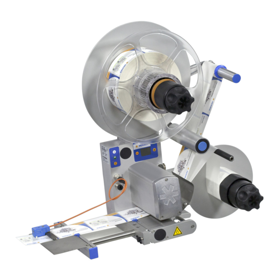
Overview and sub-assemblies Overview Sub-assemblies: Unwinder (alternatively: motorized unwinder) Label web brake Label sensor (here: FS03; alternatively: e.g. optoelectronic sensor) Dispensing system (here: rigid dispensing plate; alternatively: e.g. pivot beak) Backing paper take-up unit (here: standard; alternatively: motorized) Drive unit Housing The applicator shown above is a configuration example and may differ from the version delivered. -
Page 58: Sub-Assemblies
6 Translation of the original operating instructions HERMA 400 VERVIEW AND SUB ASSEMBLIES Sub-assemblies In this chapter you will find an overview of the applicator HERMA 400 and its sub-assemblies. Usually there are variants for the individual sub-assemblies, e.g. standard reel holder or motorized unwinder (each with or without loop-type unwinder), standard or motorized backing paper take-up unit, label sensor FS03 or forked light barrier etc. -
Page 59: Standard Unwinder
6 Translation of the original operating instructions HERMA 400 VERVIEW AND SUB ASSEMBLIES 6.2.1 Standard unwinder Inserting the label web > Turn handle 1 completely to the left (maximum of five steps) to unclamp the unit. > As the case may be, retract counter holder 2 (vertical versions only). - Page 60 6 Translation of the original operating instructions HERMA 400 VERVIEW AND SUB ASSEMBLIES Adjusting the reel brake (basic adjustment) The point of activation of the unwinder’s reel brake is factory-set and usually does not have to be changed. If however the label reel is too loose (activation point too late) or only moves at strong pull (activation point premature) a new basic adjustment is required.
- Page 61 6 Translation of the original operating instructions HERMA 400 VERVIEW AND SUB ASSEMBLIES Replacing the proximity switch If your unwinder is equipped with a proximity switch for detecting end of reel proceed as follows when replacing a defective switch: >...
- Page 62 6 Translation of the original operating instructions HERMA 400 VERVIEW AND SUB ASSEMBLIES Replacing the tension rings If after a long time of use tension rings 11 are worn proceed as follows when preplacing the worn rings (example with constructional width 16, vertical applicator): >...
-
Page 63: Motorized Unwinder - Slim Line Version
6 Translation of the original operating instructions HERMA 400 VERVIEW AND SUB ASSEMBLIES 6.2.2 Motorized unwinder – Slim line version Inserting the label web If using the core sleeve with tension rings take note of the explanations in section 6.2.1 as of page 59. - Page 64 6 Translation of the original operating instructions HERMA 400 VERVIEW AND SUB ASSEMBLIES Teaching the angle sensor As the case may be, e.g. in case of a new unit, you may have to teach the unit the positions of the pendulum if this is released completely and if this is moved to its maximum deflection in order to ensure a correct function and to avoid errors.
- Page 65 6 Translation of the original operating instructions HERMA 400 VERVIEW AND SUB ASSEMBLIES Error codes Error codes, i.e,. blink codes, can be acknowledged and reset by pressing the illuminated button briefly. The following codes may appear: Blinking Cause Measurement error which occurred e.g. on teaching the angle sensor (see above).
- Page 66 Switches 3 / 4 Determine the size of the unit (Ø of the take-up disk) On – On: 600 mm (23.6’’) On – Off: 400 mm (16’’) Off – On: 500 mm (19.7’’) Off – Off: 300 mm (12’’) Switches 5 / 6 Determine the core diameter of the unit On –...
- Page 67 6 Translation of the original operating instructions HERMA 400 VERVIEW AND SUB ASSEMBLIES Changing parts If you need to replace parts proceed as follows: > Remove the take-up disc 1. > Lock the unit by placing a pin into hole 2 (fig. B).
-
Page 68: Motorized Loop-Type Unwinder - Slim Line Version
6 Translation of the original operating instructions HERMA 400 VERVIEW AND SUB ASSEMBLIES 6.2.3 Motorized loop-type unwinder – Slim line version Inserting the label web > Insert the label reel such that the labels reach the dispensing beak in the correct position. - Page 69 6 Translation of the original operating instructions HERMA 400 VERVIEW AND SUB ASSEMBLIES Functions of the illuminated button There are several functions for the illuminated button a: – Switching the unit on/off – Error indication via blink codes For these functions see the following table, or respective sections.
- Page 70 6 Translation of the original operating instructions HERMA 400 VERVIEW AND SUB ASSEMBLIES Configuring the unit with DIP switches The DIP switches located on the main circuit board can be used for certain settings with the help of which the unit is configured. Note: This basic winder unit is not only used for the motorized unwinder but also for the motorized rewinder and the loop unwinder.
- Page 71 6 Translation of the original operating instructions HERMA 400 VERVIEW AND SUB ASSEMBLIES Changing parts If you need to replace parts proceed as follows: > Remove the take-up disc 1. > Lock the unit by placing a pin into hole 2 (fig. B).
-
Page 72: Label Web Brake
6 Translation of the original operating instructions HERMA 400 VERVIEW AND SUB ASSEMBLIES 6.2.4 Label web brake Inserting the label web > A: Push brake plate towards direction a to disengage it and at the same time towards direction b to loosen it (B). - Page 73 6 Translation of the original operating instructions HERMA 400 VERVIEW AND SUB ASSEMBLIES Cleaning > F: Push brake plate towards direction a to disengage it and at the same time towards direction b to loosen and fully retract it (G-I)....
-
Page 74: Label Sensor Fs03
6 Translation of the original operating instructions HERMA 400 VERVIEW AND SUB ASSEMBLIES 6.2.5 Label sensor FS03 Einstelltaste 680297 The label sensor FS03 is a self-learning unit, suitable for paper labels as well as electrically conducting labels (metallized or aluminium-covered). The unit is set such that the sensor is high-active on the label (1-signal on the label). -
Page 75: Setting Mode
6 Translation of the original operating instructions HERMA 400 VERVIEW AND SUB ASSEMBLIES Positioning the label Depending on the application labels have to be peeled off completely (for suction), or a small part of the label remains attached to the backing paper (for tearing off, i.e. - Page 76 6 Translation of the original operating instructions HERMA 400 VERVIEW AND SUB ASSEMBLIES Overview Buttonpress <2s >2s, <10s >10s, <15s >15s, <20s >20s Function Basic state Teaching Label material Offset Factory setting (off) (on) (blinking) (off) (on) — after end of...
- Page 77 6 Translation of the original operating instructions HERMA 400 VERVIEW AND SUB ASSEMBLIES Buttonpress Function triggered / activated duration >15s, <20s LED is off , adjusting the offset. After releasing the button a blink sequence indicates the offset currently set (the standard value for paper labels is 6, for metal labels 10).
- Page 78 6 Translation of the original operating instructions HERMA 400 VERVIEW AND SUB ASSEMBLIES Technical Data Operating voltage: 15 – 30V DC Rated current consumption: 25mA Output current: max. 20mA Output voltage low/high: 2.5V / UB - 3.5V...
-
Page 79: Label Sensor Optoelectronic
6 Translation of the original operating instructions HERMA 400 VERVIEW AND SUB ASSEMBLIES 6.2.6 Label sensor optoelectronic Cross adjustment > Loosen knurled nut 8. > Move scanning spot of photoelectric cell 1 (see locating mark) over passing label web. >... - Page 80 6 Translation of the original operating instructions HERMA 400 VERVIEW AND SUB ASSEMBLIES Positioning the label Depending on the application labels have to be peeled off completely (for suction), or a small part of the label remains attached to the backing paper (for tearing off, i.e.
-
Page 81: Dispensing Sytems
6 Translation of the original operating instructions HERMA 400 VERVIEW AND SUB ASSEMBLIES 6.2.7 Dispensing sytems Explanations / Illustrations for threading the label web you will find in chapter 4. 6.2.7.1 Rigid/Straight dispensing plates Dispensing plate straight Dispensing plate straight, Dispensing plate, 75°... -
Page 82: Dispensing Plate, 15° Angular
6 Translation of the original operating instructions HERMA 400 VERVIEW AND SUB ASSEMBLIES 6.2.7.2 Dispensing plate, 15° angular Inserting the label web > Pull snaplock 1. Fold up holding-down plate 2. > Pass label web below guide roller 3 and holding-down plate 2. -
Page 83: Pivot Beak / Application Unit
6 Translation of the original operating instructions HERMA 400 VERVIEW AND SUB ASSEMBLIES 6.2.7.3 Pivot beak / Application unit Pivot beak Application unit Adjusting the pivot beak / the application unit > Adjust paper guide 1 such that the label web sits close to screw head 2 and paper guide 1. -
Page 84: Moving Beak
6 Translation of the original operating instructions HERMA 400 VERVIEW AND SUB ASSEMBLIES 6.2.7.4 Moving beak ❏ Pneumatic working pressure must not exceed 5 bar. CAUTION Danger of crushing! Inserting the label web > Pass the label web around guide roller 1, towards the dispensing plate 2 and around the front edge. -
Page 85: Transfer Systems
6 Translation of the original operating instructions HERMA 400 VERVIEW AND SUB ASSEMBLIES 6.2.8 Transfer systems 6.2.8.1 Telescope One of several possible telescopes (linear units) may be used in your machine, depending on the application. These units are maintenance-free. ... -
Page 86: Transverse Transfer System
6 Translation of the original operating instructions HERMA 400 VERVIEW AND SUB ASSEMBLIES 6.2.8.2 Transverse transfer system Inserting the label web A Unlock the dispensing plate 2 by pulling the two snap- in knobs 1 simultaneously. B Pass the label web below roller 3 and braking plate 4, around the dispensing plate and underneath the unit to the back (C). - Page 87 6 Translation of the original operating instructions HERMA 400 VERVIEW AND SUB ASSEMBLIES Positioning the suction plate E You have to adjust the position of the suction plate only if you use different label material. Determine the vertical distance between dispensing plate and suction plate with the help of eccentric bolt 7.
- Page 88 6 Translation of the original operating instructions HERMA 400 VERVIEW AND SUB ASSEMBLIES Changing the suction plate J – K > Remove pneumatic hose from the suction plate. For this purpose press the blue collar 15 when pulling. > Remove bolt 13 to loosen the cylinder from holder 14.
-
Page 89: Drive/Transport Roller
6 Translation of the original operating instructions HERMA 400 VERVIEW AND SUB ASSEMBLIES 6.2.9 Drive/Transport roller ❏ Do not reach into the area where the feed roller draws in the WARNING web when machine is on! ❏ U.K. only: Do not remove the nip roller guard. -
Page 90: Backing Paper Take-Up Unit Standard
6 Translation of the original operating instructions HERMA 400 VERVIEW AND SUB ASSEMBLIES 6.2.10 Backing paper take-up unit standard Inserting the backing paper > Turn handle 1 completely to the left (maximum of five steps) to unclamp the unit. >... - Page 91 6 Translation of the original operating instructions HERMA 400 VERVIEW AND SUB ASSEMBLIES Basic adjustment of the lever If after a very long time of use rewinding does not function reliably anymore proceed as follows when effecting the basic adjustment: >...
- Page 92 6 Translation of the original operating instructions HERMA 400 VERVIEW AND SUB ASSEMBLIES > Deflect lever 20 widely. Tighten clamping screw 18 slightly (not completely) such that the lever remains deflected after letting go but still can be turned manually. Make sure at the same time that clamping piece 17 is fixed on the shaft without play.
- Page 93 6 Translation of the original operating instructions HERMA 400 VERVIEW AND SUB ASSEMBLIES Replacing the handle If after a very long time of use clamping of the backing paper with handle 1 does not function properly anymore proceed as follows when preplacing a worn handle: >...
- Page 94 6 Translation of the original operating instructions HERMA 400 VERVIEW AND SUB ASSEMBLIES > Remove sleeve 3 after removing screw 14. > Pull off remaining parts. When remounting the core sleeve in reverse order with the new tension rings make sure that the screws (12, 14) together with the plug-in parts 15 (with pins) are aligned exactly onto the respective holes 16.
-
Page 95: Motorized Rewinder - Slim Line Version
6 Translation of the original operating instructions HERMA 400 VERVIEW AND SUB ASSEMBLIES 6.2.11 Motorized rewinder – Slim line version Switching the unit off > You can switch off the drive with the help of switch 5 at the side of the housing. - Page 96 6 Translation of the original operating instructions HERMA 400 VERVIEW AND SUB ASSEMBLIES Inserting the backing paper For an overview see also sections 4.1.7 and 4.1.8. > Turn handle 1 completely to the left (maximum of five steps) to unclamp the unit.
- Page 97 6 Translation of the original operating instructions HERMA 400 VERVIEW AND SUB ASSEMBLIES Replacing the tension rings If after a very long time of use tension rings 11 are worn proceed as follows when preplacing the worn rings (example with constructional width 24): >...
- Page 98 6 Translation of the original operating instructions HERMA 400 VERVIEW AND SUB ASSEMBLIES When remounting the core sleeve in reverse order with the new tension rings make sure that the screws (12, 14) together with the plug-in parts 15 (with pins) are aligned exactly onto the respective holes 16.
- Page 99 6 Translation of the original operating instructions HERMA 400 VERVIEW AND SUB ASSEMBLIES Functions of the illuminated button There are several functions for the illuminated button a: – Switching the unit on/off – Teaching the angle sensor – Error indication via blink codes ...
- Page 100 6 Translation of the original operating instructions HERMA 400 VERVIEW AND SUB ASSEMBLIES If teaching was not successful an error code will be issued (see below) and the procedure must be repeated. ❏ The factory-set maximum deflection of the pendulum may NOTICE constructionally be decreased by a maximum of 20°...
- Page 101 Switches 3 / 4 Determine the size of the unit (Ø of the take-up disc) On – On: 600 mm (23.6’’) On – Off: 400 mm (16’’) Off – On: 500 mm (19.7’’) Off – Off: 300 mm (12’’) Switches 5 / 61 Determine the core diameter of the unit On –...
- Page 102 6 Translation of the original operating instructions HERMA 400 VERVIEW AND SUB ASSEMBLIES Changing parts If you need to replace parts proceed as follows: > Remove the take-up disc 1. > Lock the unit by placing a pin into hole 2 (fig. B).
-
Page 103: Troubleshooting
Troubleshooting Indication of malfunctions With HERMA 400 applicators the type of malfunction is indicated via the display (see section 7.1.1). Also, the LEDs of the key pad will give an indication (see section 7.1.2 „Malfunction table (LED indication)“). Acknowledging malfunctions If the applicator is connected to a superordinate control malfunctions very often are acknowledged centrally (e.g. - Page 104 7 Translation of the original operating instructions HERMA 400 ROUBLESHOOTING 7.1.1 List of malfunctions (indicated via display) Malfunctions are indicated with a three-digit number after the text „SM“. The next line will contain the actual text of the malfunction. SM910:...
- Page 105 7 Translation of the original operating instructions HERMA 400 ROUBLESHOOTING 7.1.1.8 SM114 Transfer unit does not leave home position There are sensors that check the positions of this component. If one of these positions is not reached or left in time a corresponding message will appear. These problems usually have some mechanical cause which you will easily detect.
- Page 106 7 Translation of the original operating instructions HERMA 400 ROUBLESHOOTING 7.1.1.15 SM148 Missing label series fault (web break?) This message appears if the label sensor could not detect a label three consecutive times (or as many times as set with the corresponding parameter (if any)). Check the sensor (setting) or your label material.
- Page 107 SM198 CAN communikation Response time This message appears if the response to a switching operation took too long. Please turn to our Technical Service or to your HERMA partner if this malfunction occurs repeatedly. 7.1.1.32 SM199 CAN communication no CAN module detected This message appears if there is no connection to the required CAN module.
- Page 108 SM825 Loop unwinder failure TEACH process This message appears if on teaching the unit‘s function an error occurred. This message is unlikely to occur. Please turn to our Technical Service or to your HERMA partner if this malfunction occurs repeatedly.
-
Page 109: Sm919 Drive Failure Low Voltage (Peak)
7.1.1.58 SM918 Drive failure This message appears if during initialization a connection to the motor encoder could not be established. Please turn to our Technical Service or to your HERMA partner if this malfunction occurs repeatedly. 7.1.1.59 SM919 Drive failure Low voltage (peak) This message appears if there is s short low voltage in the intermiediate circuit. -
Page 110: Sm921 Drive Failure
7.1.1.63 SM923 Drive failure This message appears if there is a high discrepancy between nominal and current position. May indicate an overload. Please turn to our Technical Service or to your HERMA partner if this malfunction occurs repeatedly. 7.1.1.64 SM924 Drive failure Overload This message appears if there is a drive failure with following switching off the PWM amplifier. -
Page 111: Malfunction Table (Led Indication)
7 Translation of the original operating instructions HERMA 400 ROUBLESHOOTING 7.1.2 Malfunction table (LED indication) Acknowledge Malfunction Feed Reset (ext.) (ext.) (ext.) Clamping lever open (nip roller), web break, • • • • • or missing stop signal (label sensor) –... -
Page 112: Remedy Of Malfunctions
> Check label sensor (stop signal), replace if required. > Use only the correct chip belonging to the applicator > Please turn to our Technical Service or to your HERMA partner if a malfunction occurs repeatedly. > Check voltage. >... -
Page 113: Other Malfunctions
7 Translation of the original operating instructions HERMA 400 ROUBLESHOOTING Other malfunctions On the following pages you will find a table with possible malfunctions that you can correct by yourself. In case of malfunctions or defects that you cannot correct please contact our Technical Service (see section 7.4). - Page 114 7 Translation of the original operating instructions HERMA 400 ROUBLESHOOTING Malfunction Cause Remedy Label web tears Backing paper punched. Reduce backing paper ten- sion, reduce pressure of label-web brake (section 6.2.4). Label remainders clamped Clean sensing/scanning beneath sensing/scanning unit (chapter 8).
-
Page 115: Replace The Drive Unit
7 Translation of the original operating instructions HERMA 400 ROUBLESHOOTING Replace the drive unit ❏ Principally the firmware of the drive unit and the firmware of NOTICE the CAN I/O board must be of the same version. If they do not you may receive error message SM169. - Page 116 7 Translation of the original operating instructions HERMA 400 ROUBLESHOOTING Back of the applicator housing > Loosen the motor cables (mains plug (pin1+3) 1, protective earth conductor 2 and 34channel control cable 3). > Remove the I/O circuit board 4.
-
Page 117: Ship The Drive Unit
Make sure to pack the drive unit such that it is non-slip and well padded. > Send the drive unit to be replaced to the Technical Service of HERMA GmbH with giving the reason for return. The address you will find in section 7.4. - Page 118 7 Translation of the original operating instructions HERMA 400 ROUBLESHOOTING www.herma.com www.herma-components.com info@herma.com 118/130 3.26 EN (200416)
-
Page 119: Cleaning, Maintenance, Service
❏ Before opening control box or labeller housing, disconnect WARNING from mains! ❏ When cutting the HERMA 400 applicator off mains you must wait for at least five minutes before opening the housing or touching connector pins. RESIDUAL VOLTAGES! >... - Page 120 8 Translation of the original operating instructions HERMA 400 LEANING MAINTENANCE SERVICE Wichtig: Opening the screws at the front of the drive unit NOTICE HERMA 400 will void the warranty! 120/130 3.26 EN (200416)
-
Page 121: Technical Data
Power supply / Line voltage Wide range input 100V AC ... 240V AC ±10%, 50 Hz ... 60 Hz Max. power consumption 400 W + n times 100W (n=number of motorized winder units) Leakage current, according to EN 60335-1 110VAC:<0.35 mA 150VAC:<0.5 mA... - Page 122 Translation of the original operating instructions HERMA 400 ECHNICAL Winder system SlimLine Max. reel width for reel diameter of 400 mm: 320 mm(16’’: 12.6’’) 500 mm: 200 mm(20’’: 7.8’’) 600 mm: 160 mm(23.6’’: 6.3’’) Max. unwinding speed for core diameter of 3’’ : 120 m/min...
-
Page 123: Inputs / Outputs (X10) (Option, Standard Signals)
9 Translation of the original operating instructions HERMA 400 ECHNICAL Inputs / outputs (X10) (option, standard signals) This optional connector provides inputs/outputs to the external control (e.g. PLC). ➜97941 Designation Description Color Led3 brown X22.8 LED function key (printer status) -
Page 124: Inputs / Outputs (X19) (Option, Extended Signals)
9 Translation of the original operating instructions HERMA 400 ECHNICAL Inputs / outputs (X19) (option, extended signals) This optional connector provides inputs/outputs to the external control (e.g. PLC). ➜97941 Designation Description Color +24V Power supply (<150mA) brown X31.9 Ground (all voltages DC) blue X31.2... -
Page 125: Declaration Of Incorporation
EC Machinery Directive 2006/42/EC, annex II B The manufacturer HERMA GmbH – Geschäftsbereich Etikettiermaschinen – Plochinger Straße 48, 73779 Deizisau / Germany hereby declares that the following partly completed machinery complies with the basic requirements of the following directives EC EMC Directive 2014/30/EU... - Page 126 10 Translation of the original operating instructions HERMA 400 ECLARATION OF NCORPORATION Note: After incorporating the applicator HERMA 400 into your machine or connecting it with other machines / machine parts you are obliged to carry out an evaluation of conformity for this new machine or assembly of machines! ...
-
Page 127: Spare Parts
Spare parts Online ordering You can conveniently order your spare parts for the HERMA 400 applicator in HERMA‘s online shop: www.herma-components.com Ordering information > For other processing of spare parts orders we absolutely need the material number (Mat.-No.). In order to avoid queries please state applicator number as well. ... - Page 128 11 Translation of the original operating instructions HERMA 400 PARE PARTS www.herma.com www.herma-components.com info@herma.com 128/130 3.26 EN (200416)
-
Page 129: A1 Index
Translation of the original operating instructions HERMA 400 Index Acknowledging errors 27 Key designations 3 Adhesive labels 17 Key pad at the applicator 26 Angle sensor 64 Annulus labels 39 Label attachment 33 Application type 41 Label positioning at dispensing beak 75... - Page 130 Translation of the original operating instructions HERMA 400 Safety notes 11 Safety notes, symbols for 2 Schemes label web threading 19 Sense of rotation master encoder 35 Sense of rotation of the winder unit, changing the 63 Sensor mark 37...
Need help?
Do you have a question about the 400 and is the answer not in the manual?
Questions and answers