Table of Contents
Advertisement
Quick Links
COMBI
CAUTION, MICROWAVE RADIATION ........................................................................ INSIDE FRONT COVER
WARNING .......................................................................................................................................................... 1
SERVICING ...................................................................................................................................................... 2
PRODUCT SPECIFICATIONS ......................................................................................................................... 5
GENERAL INFORMATION ................................................................................................................................ 5
APPEARANCE VIEW ....................................................................................................................................... 6
OPERATION SEQUENCE ................................................................................................................................ 7
FUNCTION OF IMPORTANT COMPONENTS ............................................................................................... 10
TROUBLESHOOTING GUIDE ....................................................................................................................... 12
TEST PROCEDURE ....................................................................................................................................... 14
CONTROL UNIT ASSEMBLYL ........................................................................................................................ 23
PRECAUTIONS FOR USING LEAD-FREE SOLDER ..................................................................................... 27
COMPONENT REPLACEMENT AND ADJUSTMENT PROCEDURE ........................................................... 28
MICROWAVE MEASUREMENT .................................................................................................................... 35
TEST DATA AT A GLANCE ............................................................................................................................ 36
WIRING DIAGRAM ......................................................................................................................................... 37
PICTORIAL DIAGRAM ................................................................................................................................... 40
POWER UNITL CIRCUIT ................................................................................................................................ 41
CPU UNITL CIRCUIT ...................................................................................................................................... 42
GRID ASSIGNMENT OF FLUORESENT DISPLAY TUBE ............................................................................. 43
PRINTED WIRING BOARD ............................................................................................................................. 44
PARTS LIST ................................................................................................................................................... 45
SERVICE MANUAL
MODEL
In the interest of user-safety the oven should be restored to its original
condition and only parts identical to those specified should be used.
TABLE OF CONTENTS
SHARP CORPORATION
51
HIGH SPEED CONVECTION
MICROWAVE OVEN
R-90GCH
R-90GCH
SY210R90GCPH/
Page
Advertisement
Table of Contents

Related Manuals for Sharp R-90GCH


Summary of Contents for Sharp R-90GCH
-
Page 1: Table Of Contents
R-90GCH SERVICE MANUAL SY210R90GCPH/ HIGH SPEED CONVECTION COMBI MICROWAVE OVEN R-90GCH MODEL In the interest of user-safety the oven should be restored to its original condition and only parts identical to those specified should be used. TABLE OF CONTENTS Page CAUTION, MICROWAVE RADIATION ................ -
Page 2: Caution Microwave Radiation
R-90GCH CAUTION MICROWAVE RADIATION Personnel should not be exposed to the microwave energy which may radiate from the magnetron or other microwave generating devices if it is improperly used or connected. All input and output microwave connections, waveguides, flanges and gaskets must be secured. -
Page 3: Warning
MICROWAVE OVEN R-90GCH GENERAL INFORMATION GENERAL IMPORTANT INFORMATION This Manual has been prepared to provide Sharp Corp. Service engineers with Operation and Service Information. APPEARANCE VIEW It is recommended that service engineers carefully study the entire text of this manual, so they will be qualified to render satisfactory customer service. -
Page 4: Servicing
Indien het water nog steeds Sharp beveelt ten sterkste aan dat, voor zover mogelijk, koud is, herhaalt u de allereerste drie stappen en controleer defecten worden opgespoord wanneer de stekker uit het nogmaals de aansluitingen naar de geteste onderdelen. - Page 5 är kallt utför Du 3 steg kontroller och kontrollerar anslutningarna till varje enskild komponent på nytt. Sharp rekommenderar att felsökning sker med strömmen fränkopplad. Ibland kan det var nödvändigt att koppla på När all service är klar och ugnen ihopskruvad skall ugnens strömmen efter det att höljet avlägsnats, utför da 3 Steg...
- Page 6 Sharp raccomanda, nei limiti del possibile, che la ricerca dei guasti avvenga in assenza di alimentazione elettrica. Dopo aver portato a termine le operazioni di manutenzione In alcuni casi tuttavia, può...
-
Page 7: Product Specifications
R-90GCH PRODUCT DESCRIPTION SPECIFICATION ITEM DESCRIPTION Power Requirements 230 Volts / 50 Hertz / Single phase, 3 wire earthed Power Consumption Microwave cooking 1.8 kW Approx. 8.2 A Grill cooking 2.9 kW Approx. 12.6 A Convection cooking 2.9 kW Approx. 12.6 A DUAL 1 cooking 3.2 kW Approx. -
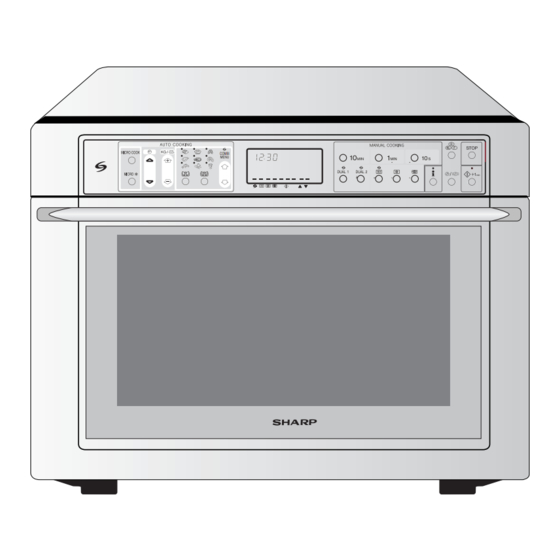
Page 8: Appearance View
R-90GCH APPEARANCE VIEW OVEN 1. Control panel 2. Waveguide cover (DO NOT REMOVE) 3. Oven lamp 4. Oven cavity 5. Coupling 6. Door latches 11. Power cord 7. Door opening handle 12. Air-vent openings (To open the door, pull the handle down and forward. -
Page 9: Operation Sequence
R-90GCH OPERATION DESCRIPTION OF OPERATING SEQUENCE The following is a description of component functions to negative voltage of approximately 4000 volts D.C.. during oven operation. 4. The 2450 MHz microwave energy produced in the magnetron generates a wavelength of 12.24 cm. This... - Page 10 R-90GCH 5. Upon completion of the cooking time, the audible signal rent-limiting relay RY2. The following levels of microwave will sound, and oven lamp, turntable motor, cooling fan power are given. motor and convection motor are de-energized. At the 32 sec. ON...
- Page 11 R-90GCH (COM-NO) of relay RY6 are opened. AUTOMATIC COOKING 2. The damper is moved to the closed position. Automatic cooking will automatically compute the oven 3. The solid-state relays (SSR1+SSR2) and relay RY2 temperature, microwave power and cooking time. And the are energized, and the main supply voltage is applied oven will cook according to the special cooking sequence.
-
Page 12: Function Of Important Components
R-90GCH The LSI also stops counting down and closes the 0 2 3 31 32 (sec.) 64 (sec.) 3 sec. damper door so that no fresh air will enter the oven CONVECTION MOTOR cavity. 4. Once the fire sensor feature has shut the unit down, the 3 sec. - Page 13 R-90GCH MAGNETRON TEMPERATURE FUSE TF FAN MOTOR (HIGH VOLTAGE TRANSFORMER SIDE) FM The temperature fuse located on the waveguide flange is designed to prevent damage to the magnetron if an over The fan motor drives a blade which draws external cool air.
-
Page 14: Troubleshooting Guide
R-90GCH at the top of the oven cavity into a condensation compart- Oven cavity left side ment. Convection, Preheat, Grill, Dual1, Dual2, or all cook- ing modes which use the top / side heating elements: Damper is in the closed position, so that no hot air will be... - Page 15 R-90GCH (CONVECTION/ CONDITION OFF CONDITION COOKING CONDITION (MICROWAVE) GRILL/ DUAL) POSSIBLE CAUSE DEFECTIVE PARTS MAGNETRON HIGH VOLTAGE TRANSFORMER H.V. RECTIFIER ASSEMBLY HIGH VOLTAGE CAPACITOR C1 SECONDARY INTERLOCK SWITCH SW1 3RD. LATCH SWITCH SW3 DOOR SENSING SWITCH SW4 MONITOR SWITCH SW2...
-
Page 16: Test Procedure
R-90GCH TEST PROCEDURES PROCEDURE COMPONENT TEST LETTER MAGNETRON ASSEMBLY TEST NEVER TOUCH ANY PART IN THE CIRCUIT WITH YOUR HAND OR AN INSULATED TOOL WHILE THE OVEN IS IN OPERATION. CARRY OUT 3D CHECKS. 2. Remove the back plate from the oven, referring to “BACK PLATE REMOVAL”. - Page 17 R-90GCH TEST PROCEDURES PROCEDURE COMPONENT TEST LETTER Room temperature ....... To = 21˚C Initial temperature ....T1 = 11°C Temperature after (42 + 3) = 45 sec..............T2 = 21°C Temperature difference Cold-Warm ..............∆T1 = 10°C Measured output power The equation is “P = 100 x ∆T”...
- Page 18 R-90GCH TEST PROCEDURES PROCEDURE COMPONENT TEST LETTER NOTE: FOR MEASUREMENT OF THE RESISTANCE OF THE RECTIFIER, THE BATTERIES OF THE MEASURING INSTRUMENT MUST HAVE A VOLTAGE AT LEAST 6 VOLTS, BECAUSE OTHERWISE AN INFINITE RESISTANCE MIGHT BE SHOWN IN BOTH DIRECTIONS.
- Page 19 R-90GCH TEST PROCEDURES PROCEDURE COMPONENT TEST LETTER BLOWN FUSE F1 20A 1. CARRY OUT 3D CHECKS. 2. If the fuse F1 20A is blown, there is a shorts or grounds in electrical parts or wire harness Check then and replace the defective parts or repaire the wire harness.
- Page 20 R-90GCH TEST PROCEDURES PROCEDURE COMPONENT TEST LETTER TOP HEATING ELEMENT H1 TEST 1. CARRY OUT 3D CHECKS. 2. Make sure the heating element is fully cooled and test as follows; a. Disconnect wire leads from the heating element and measure the resistance with an ohmmeter.
- Page 21 R-90GCH TEST PROCEDURES PROCEDURE COMPONENT TEST LETTER 2. Disconnect the leads to the primary of the high voltage transformer. 3. Ensure that the leads remain isolated from other components and oven chassis by using insulation tape. 4. Disconnect the wire leads from the switch terminals and connect ohmmeter leads to the common (COM.) and normally open (N.O.) terminals of the switch.
- Page 22 R-90GCH TEST PROCEDURES PROCEDURE COMPONENT TEST LETTER Difference in power supply voltage will also affect the oven temperature. The Household power supply voltage may sometimes become lower than the rated voltage and cause under-cooking. If the power supply voltage is 10% lower than the rated voltage, longer cooking time is required by 10% to 20%.
- Page 23 R-90GCH TEST PROCEDURES PROCEDURE COMPONENT TEST LETTER b) Clock does not operate properly. c) Cooking is not possible. d) Proper temperature measurment is not obtained. When testing is completed, CARRY OUT 4R CHECKS. TACT SWITCH TEST CARRY OUT 3D CHECKS.
- Page 24 R-90GCH TEST PROCEDURES PROCEDURE COMPONENT TEST LETTER 1) CARRY OUT 3D CHECKS. 2) If the Fuse 1 is blown, replace the power unit. 3) Make a visual inspection of the varistor. Check for burned damage and examine the touch control transformer with a tester for the presence of layer short-circuit (check the primary coil resistance which is approximately 275Ω...
-
Page 25: Control Unit Assemblyl
R-90GCH TOUCH CONTROL PANEL ASSEMBLY OUTLINE OF TOUCH CONTROL PANEL The touch control section consists of the following units 5) Buzzer Circuit as shown in the touch control panel circuit. The buzzer is responds to signals from the LSI to emit noticing sounds (tact switch touch sound and completion (1) Tact switch circuit on the CPU unit. - Page 26 R-90GCH Pin No. Signal Description AN15 Primary input voltage watching terminal. The LSI is watching the primary input voltage through this terminal. 8-10 Input terminal to change the specification according to the model. AN14-AN12 AN11 Temperature measurement input: OVEN THERMISTOR.
- Page 27 R-90GCH Pin No. Signal Description Cooling fan motor driving signal. To turn on and off shut-off relay(RY5). “L” level During cooking during both microwave and convection cooking; “H” level otherwise Damper motor relay driving signal. H : GND To turn on and off shut-off relay(RY4).
- Page 28 R-90GCH Pin No. Signal Description Tact switch strobe signal......Signal applied to tact switch section. LED driving signal..Signal is applied to the Light-emitting diodes (LD10-11). Tact switch strobe signal......Signal applied to tact switch section. LED driving signal..Signal is applied to the Light-emitting diodes (LD8-9).
-
Page 29: Precautions For Using Lead-Free Solder
R-90GCH PRECAUTIONS FOR USING LEAD-FREE SOLDER 1. Employing lead-free solder The "Main PWB" of this model employs lead-free solder. This is indicated by the "LF" symbol printed on the PWB and in the service manual. The suffix letter indicates the alloy type of the solder. -
Page 30: Component Replacement And Adjustment Procedure
4. If the outer case (cabinet) is not fitted. WARNING FOR WIRING To prevent an electric shock, take the following 3) Sharp edge: precautions. Bottom plate, Oven cavity, Waveguide flange, 1. Before wiring, Chassis support and other metallic plate. - Page 31 R-90GCH TERMINAL INSULATOR REPLACEMENT 1. Open covers of the terminal insulator by using small Installation flat type screw driver. 1. Insert the receptacle into terminal insulator. 2. Remove the receptacle from the terminal insulator. 2. Close covers of the terminal insulator, as shown 3.
- Page 32 R-90GCH 10.Carefully remove the four (4) screws holding the CAUTION: WHEN REPLACING THE MAGNETRON, BE magnetron to the waveguide. When removing the SURE THE R.F. GASKET IS IN PLACE AND screws, hold the magnetron to prevent it from falling. THE MAGNETRON MOUNTING SCREWS 11.Remove the magnetron from the unit with care so the...
- Page 33 R-90GCH HEATER DUCT LEFT ASSEMBLY, HEATER DUCT UPPER ASSEMBLY AND CONVECTION DUCT ASSEMBLY REMOVAL 1. CARRY OUT 3D CHECKS. 16.Remove the PWB mounting angle with the power unit 2. Remove the back plate from the oven, referring to from the bottom plate.
- Page 34 6. Now, the top heating element is free. TURNTABLE MOTOR REMOVAL 1. Disconnect the oven from power supply. areas flat. No sharp edges must be evident after 2. Wait for 60 seconds to discharge the high voltage removal of the turntable motor.
- Page 35 R-90GCH After adjustment, check the following. SW2: Monitor switch 1. In and out play of the door remains less than 0.5 mm when in the latched position. First check the position of Latch hook left the latch hook right, pushing and pulling right portion of...
- Page 36 R-90GCH Left door cam pin Door cam left Oven hinge left Door assembly Left door hinge pin Right door cam pin Door cam right Oven hinge right Right door hinge pin Figure C-4(b). Door Replacement DOOR DISASSEMBLY 1. CARRY OUT 3D CHECKS.
-
Page 37: Microwave Measurement
R-90GCH CPU unit melted and transformed by heat. But it is not abnormal and no problem to use the oven. 6. Remove the two (2) screws holding the panel angle to the panel sub assembly. Screw 7. Release the panel angle from the two (2) tabs of the Bottom side of panel sub assembly first. -
Page 38: Test Data At A Glance
R-90GCH TEST DATA AT A GLANCE PARTS SYMBOL VALUE / DATA Fuse 20A 250V Fuse F10A High voltage fuse 0.75A 5 kV Thermal cut-out 170°C Off / 155˚C On Thermal cut-out 150°C Off / 130˚C On Temperature fuse 150°C Off Thermistor Approx. -
Page 39: Wiring Diagram
R-90GCH... - Page 40 R-90GCH...
- Page 41 R-90GCH...
-
Page 42: Pictorial Diagram
R-90GCH... -
Page 43: Power Unitl Circuit
R-90GCH 6.8 1W D1-D4 1N4002L x4 DTA143ES R5 300 KIA79L05P AC230V H-13 /50Hz 1.5K 1/4W TURN OVER TURN OVER MOTOR DAMPER MOTOR CONVECTION MOTOR MOTOR DTD143ES DAMPER MOTOR WATCH CONVECTION MOTOR H-12 DOOR (B) (J1) 1N5817 H-11 DOOR (A) 150 1/2W... -
Page 44: Cpu Unitl Circuit
R-90GCH... -
Page 45: Grid Assignment Of Fluoresent Display Tube
R-90GCH col1 col1 col2 col2 [ 1G - 10G ] Figure S-4. Grid Assignment of Fluoresent Display Tube... -
Page 46: Printed Wiring Board
R-90GCH (J1) (ZD6) (Q3) E C B E C B (R7) (J2) -
Page 47: Parts List
R-90GCH PARTS LIST ∆ Note: The parts marked " " may cause undue microwave exposure. The parts marked "*" are used in voltage more than 250V. REF. NO. PART NO. DESCRIPTION Q'TY CODE ELECTRICAL PARTS RC-QZA315WRZZ High voltage capacitor RC-QZA314WRZZ... - Page 48 R-90GCH REF. NO. PART NO. DESCRIPTION Q'TY CODE 4-15 FDUC-A369WRKZ Exhaust duct 4-16 FFANMA016WRKZ Convection fan assembly 4-17 LANGFA243WRPZ Convection motor mounting angle 4-18 PDUC-A825WRPZ Convection duct 4-19 PFPF-A229WREZ Thermal insulator back 4-20 PREFHA072WRWZ Thermal cover back 4-21 PSKR-A388WRWZ Divide plate A...
- Page 49 R-90GCH REF. NO. PART NO. DESCRIPTION Q'TY CODE 5-18 MSPRCA137WREZ Latch spring Right 5-19 MSPRCA138WREZ Latch spring Left 5-20 XEPSD40P08000 Screw : 4mm x 8mm 5-21 XEPSD40P20000 Screw : 4mm x 20mm 5-22 LPIN-A179WREZ Handle pin 5-23 LX-BZ0139WRE0 Special screw...
- Page 50 R-90GCH...
- Page 51 R-90GCH CONTROL PANEL PARTS 3-2-1A 3-2-1B 3-3-3 DOOR PARTS 3-3-1 5-21 3-3-2 5-21 5-14 5-14 5-17 5-13 5-17 5-21 5-22 5-23 5-19 5-21 5-24 5-22 5-16 5-20 5-11 5-20 5-25 5-20 5-20 5-10 5-12 5-20 5-18 5-23 MISCELLANEOUS 5-15 5-10...
- Page 52 TRAY PAD SPADPA621WREZ PACKING CASE SPAKCD829WREZ Not replaceable items. COPYRIGHT © 2002 BY SHARP CORPORATION ALL RIGHTS RESERVED. No part of this publication may be reproduced, stored in retrieval systems, or transmitted in any form or by any means, electronic, mechanical, photocopying, recording, or otherwise, without prior written permission of the publisher.
Need help?
Do you have a question about the R-90GCH and is the answer not in the manual?
Questions and answers