Table of Contents
Advertisement
CAUTION, MICROWAVE RADIATION ................................................................................................................ 1
WARNING .............................................................................................................................................................. 1
PRODUCT SPECIFICATIONS ............................................................................................................................. 2
GENERAL INFORMATION ................................................................................................................................... 2
APPEARANCE VIEW ........................................................................................................................................... 3
OPERATION SEQUENCE ................................................................................................................................... 4
FUNCTION OF IMPORTANT COMPONENTS .................................................................................................... 7
SERVICING ........................................................................................................................................................ 10
TEST PROCEDURE .......................................................................................................................................... 12
TOUCH CONTROL PANEL ................................................................................................................................ 21
COMPONENT REPLACEMENT AND ADJUSTMENT PROCEDURE ............................................................... 27
MICROWAVE MEASUREMENT ........................................................................................................................ 32
WIRING DIAGRAM ............................................................................................................................................. 33
PICTORIAL DIAGRAM ....................................................................................................................................... 35
CONTROL PANEL CIRCUIT .............................................................................................................................. 36
PRINTED WIRING BOARD ................................................................................................................................ 37
PARTS LIST ........................................................................................................................................................ 38
SERVICE MANUAL
MODEL
In interests of user-safety the oven should be restored to its original
condition and only parts identical to those specified should be used.
TABLE OF CONTENTS
SHARP CORPORATION
COVECTION
MICROWAVE OVEN
R-9H56
R-9H56
S8409R9H56PJ/
Page
Advertisement
Table of Contents

Related Manuals for Sharp R-9H56


Summary of Contents for Sharp R-9H56
-
Page 1: Table Of Contents
R-9H56 SERVICE MANUAL S8409R9H56PJ/ COVECTION MICROWAVE OVEN R-9H56 MODEL In interests of user-safety the oven should be restored to its original condition and only parts identical to those specified should be used. TABLE OF CONTENTS Page CAUTION, MICROWAVE RADIATION ........................ 1 WARNING ................................ - Page 2 R-9H56...
-
Page 3: Caution Microwave Radiation
MICROWAVE OVEN R-9H56 GENERAL IMPORTANT INFORMATION APPEARANCE VIEW This Manual has been prepared to provide Sharp Corp. Service engineers with Operation and Service Information. OPERATING SEQUENCE It is recommended that service engineers carefully study the entire text of this manual, so they will be qualified to render satisfactory customer service. -
Page 4: Product Specifications
R-9H56 PRODUCT SPECIFICATIONS ITEM DESCRIPTION Power Requirements 240 Volts 50 Hertz Single phase, 3 wire earthed Power Consumption 1500 W (Microwave) 1600 W (Convection) Power Output 750 watts nominal of RF microwave energy (AS 2895 1986) 850 watts (IEC-705-1988 ) -
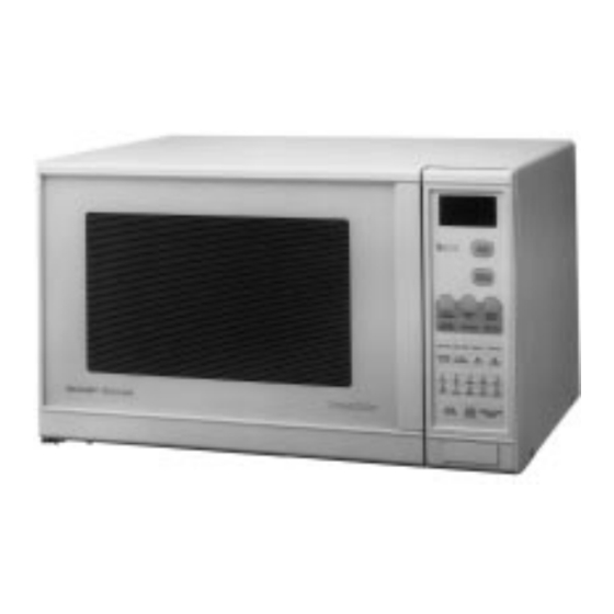
Page 5: Appearance View
R-9H56 APPEARANCE VIEW 1. Ventilation opening 2. Oven lamp 3. Door hinges 4. Door safety latches 5. See through door 6. Door open button 7. Touch control panel 8. Digital readout 9. Wave guide cover 10. Coupling 11. Access cover for oven lamp replacement 12. -
Page 6: Operation Sequence
R-9H56 OPERATION SEQUENCE The following is a description of component functions during be cooked. oven operation. 5. Upon completion of the cooking time, the power transformer, oven lamp, etc. are turned off and the Relay and Components Connection generation of microwave energy is stopped. The oven will revert to the OFF condition.. - Page 7 R-9H56 2. The coil of relay (RY4) is energized by the CPU unit. The 2. The shut-off relay (RY1+RY5+RY6) energized, turning damper is moved to the closed position, opening the on the oven lamp, turntable motor, cooling fan motor and damper switch contacts.
- Page 8 R-9H56 ment with each food category and inputted into the LSI. and/or the Convection Fan Symbol will rotate. An example of how sensor works: 2. The cooking time will appear on the display and start counting down to zero. The cooking time is adjusted automatically according to the weight of the food.
-
Page 9: Function Of Important Components
R-9H56 3. Once the fire sensor feature has shut the unit down, the 32 (sec.) 64 (sec.) 6 sec. programmed cooking cycle may be resumed by pressing CONVECTION MOTOR the "START" pad or the unit may be reset by pressing the "CLEAR"... - Page 10 R-9H56 FUSE M8A 250V FAN MOTOR 1. If the wire harness or electrical components are short- The fan motor drives a blade which draws external cool air. circuited, this fuse blows to prevent an electric shock or This cool air is directed through the air vanes surrounding fire hazard.
- Page 11 R-9H56 Microwave Cooking: 3-4. At the end of the convection cooking, shut-off relay Damper is in the open position, because a portion of cooling (RY4) is energized, and the damper is returned to the air is channelled through the cavity to remove steam and open position.
-
Page 12: Servicing
3D checks and re-examine the connections to the component being tested. Sharp recommend that wherever possible fault-finding is carried out with the supply disconnected. It may in, some cases, be necessary to connect the supply after... - Page 13 R-9H56 CK = Check / RE = Replace A B C D E E E F G G H I J J J J K L M N N N N N N O P TEST PROCEDURE RE CKCK CK RE...
-
Page 14: Test Procedure
R-9H56 TEST PROCEDURES PROCEDURE LETTER COMPONENT TEST MAGNETRON TEST NEVER TOUCH ANY PART IN THE CIRCUIT WITH YOUR HAND OR AN INSULATED TOOL WHILE THE OVEN IS IN OPERATION. CARRY OUT 3D CHECK. Isolate the magnetron from high voltage circuit by removing all leads connected to filament terminal. - Page 15 R-9H56 TEST PROCEDURES PROCEDURE LETTER COMPONENT TEST 6. Measure the final water temperature. (Example: The final temperature T2 = 21 C) 7. Calculate the microwave power output P in watts from above formula. Initial temperature ....................T1 = 11 C Temperature after (49 + 2) = 51 sec.
- Page 16 R-9H56 TEST PROCEDURES (CONT'D) PROCEDURE LETTER COMPONENT TEST Example Initial temperature ................T1 = 23˚C T2 = 24˚C Temperature after 1 min. 51 sec............T1 = 33˚C T2 = 34˚C Temperature difference Cold-Warm ..........T1 = 10˚C T2 = 10˚C Mean temperature rise T ......
- Page 17 R-9H56 TEST PROCEDURES (CONT'D) PROCEDURE COMPONENT TEST LETTER ASYMMETRIC RECTIFIER TEST CARRY OUT 3D CHECKS. Isolate the high voltage rectifier assembly from the HV circuit. The asymmetric can be tested using an ohmmeter set to its highest range across the terminals A+B of the asymmetric rectifier and note the reading obtained.
- Page 18 R-9H56 TEST PROCEDURES (CONT'D) PROCEDURE COMPONENT TEST LETTER TEMPERATURE FUSE AND THERMAL CUT-OUT TEST CARRY OUT 3D CHECKS. Disconnect the leads from the terminals of the temp. fuse or thermal cut-out. Then using an ohmmeter, make a continuity test across the two terminals as described in the table below.
- Page 19 R-9H56 TEST PROCEDURES (CONT'D) PROCEDURE COMPONENT TEST LETTER Disconnect the leads from the motor. Using an ohmmeter, check the resistance between the two terminals as described in the table below. Table: Resistance of Motor Motors Resistance Fan motor Approximately 295 Turntable motor Approximately 10.5 k...
- Page 20 R-9H56 TEST PROCEDURES (CONT'D) PROCEDURE COMPONENT TEST LETTER KEY UNIT TEST If the display fails to clear when the STOP/CLEAR pad is depressed, first verify the flat ribbon is making good contact, verify that the door sensing switch (stop switch) operates properly; that is the contacts are closed when the door is closed and open when the door is open.
- Page 21 R-9H56 TEST PROCEDURES (CONT'D) PROCEDURE COMPONENT TEST LETTER Problem: POWER ON, indicator does not light up. NOTE: *At the time of making these repairs, make a visual inspection of the varistor. check for burned damage and examine the transformer with an...
- Page 22 R-9H56 TEST PROCEDURES (CONT'D) PROCEDURE COMPONENT TEST LETTER (3) Remove the AH sensor. (4) Install the new AH sensor. (5) Re-install the outer case. (6) Reconnect the oven to the power supply and check the sensor cook operation, proceed as follows: 6-1.
-
Page 23: Touch Control Panel
R-9H56 TOUCH CONTROL PANEL ASSEMBLY OUTLINE OF TOUCH CONTROL PANEL The touch control section consists of the following units as shown in the touch control panel circuit. 4) ACL Circuit A circuit to generate a signals which resetting the LSI to (1) Key Unit the initial state when power is applied. -
Page 24: Description Of Lsi
R-9H56 DESCRIPTION OF LSI LSI(IZA589DR): The I/O signals of the LSI(IZA589DR) are detailed in the following table. Pin No. Signal Description Connected to GND. Anode (segment) of Fluorescent Display light-up voltage: -28V. Vp voltage of power source circuit input. AVSS Power source voltage: -5V. - Page 25 R-9H56 Pin No. Signal Description 20 msec. The square waveform voltage is delivered to the relay(RY1) driving circuit and During cooking relays(RY2,RY3,RY5) control circuit. 20-21 P46-P45 Terminal not used. Timing signal output terminal for temperature measurement(OVEN). "H" level (GND) : Ttermistor OPEN timing.
- Page 26 R-9H56 Pin No. Signal Description ß(50Hz) Key strobe signal. Signal applied to touch-key section. A pulse signal is input to P24-P27 terminal while one of G-5 line keys on key matrix is touched. Digit selection signal. The relationship between digit signal and digit are as follows;...
- Page 27 R-9H56 Pin No. Signal Description Segment data signal. Signal similar to P23. Key strobe signal. Signal applied to touch-key section. A pulse signal is input to P24-P27 terminal while one of G-12 line keys on key matrix is touched. Digit selection signal.
- Page 28 R-9H56 SERVICING For those models, check and repair all the controls 1. Precautions for Handling Electronic Components (sensor-related ones included) of the touch control panel This unit uses CMOS LSI in the integral part of the while keeping it connected to the oven.
-
Page 29: Component Replacement And Adjustment Procedure
R-9H56 COMPONENT REPLACEMENT AND ADJUSTMENT PROCEDURE WARNING: Avoid possible exposure to microwave energy. Please follow the instructions below before operating the oven. 1. Disconnect the oven from power supply. 1. Door does not close firmly. 2. Make sure that a definite” click” can be heard when the 2. - Page 30 R-9H56 ASYMMETRIC RECTIFIER AND HIGH VOLTAGE RECTIFIER REMOVAL 1. CARRY OUT 3D CHECKS. CAUTION: WHEN REPLACING HIGH VOLTAGE RECTI- 2. Remove one (1) screw holding the high voltage rectifier FIER ASSEMBLY, ENSURE THAT THE terminal to the capacitor holder. EARTHING SIDE TERMINAL MUST BE SE- 3.
- Page 31 R-9H56 TURNTABLE MOTOR AND/OR COUPLING REMOVAL 4. Remove the two (2) screws holding the turntable motor 1. Disconnect the oven from power supply. to the mounting plate of the oven cavity bottom. 2. Remove one (1) screw holding the turntable motor cover 5.
- Page 32 R-9H56 CAUTION: 5. Connect the wire leads to the fan motor and the thermal * Do not hit the fan blade strongly when installed cut-out, referring to the pictorial diagram. because the bracket may be transformed. Shaft * Make sure that the fan blade rotates smooth after installed.
- Page 33 R-9H56 DOOR DISASSEMBLY Remove door assembly, refer to “Door Replacement”. 2 LIFT UP Replacement of door components are as follows: PUTTY KNIFE 1. Place door assembly on a soft cloth with latches facing 1 BENT Note: As the engaging part of choke cover and door panel...
-
Page 34: Microwave Measurement
R-9H56 MICROWAVE MEASUREMENT After adjustment of door latch switches, monitor switch standard for microwave ovens must be used for testing. Recommended instruments are: and door are completed individually or collectively, the NARDA 8100 following leakage test must be performed with a survey... -
Page 35: Wiring Diagram
R-9H56 NOTE: indicates components with potential above 250V. SCHEMATIC NOTE: CONDITION OF OVEN 1. DOOR CLOSED. 2. CLOCK APPERARS ON DISPLAY Figure O-1. Oven Schematic-OFF Condition SCHEMATIC SCHEMATIC NOTE: CONDITION OF OVEN NOTE: CONDITION OF OVEN 1. DOOR CLOSED. 1. DOOR CLOSED. - Page 36 R-9H56 NOTE: indicates components with potential above 250V. SCHEMATIC NOTE: CONDITION OF OVEN 1. DOOR CLOSED. 2. CONVECTION PAD TOUCHED. 3.DESIRED TEMO. PAD TOUCHED. 4. START PAD TOUCHED. Figure O-3. Oven Schematic-Convection Cooking Condition SCHEMATIC NOTE: CONDITION OF OVEN 1. DOOR CLOSED.
-
Page 37: Pictorial Diagram
R-9H56 HV. RECTIFIER... -
Page 38: Control Panel Circuit
R-9H56 UNIT 18,24 10,14 IZA589DR R103 R102 R101 3.3K R100 (J3) (J5) (J7) (J2) (J4) (J6) 3.3K 0.1µ/50V 2.2KF 100F 47µ/16V HZ5C2 0.015µ/25V 4.7K 3.3µ/50V 1/2W 4.7µ/35V DOOR 1000µ/35V 0.1µ/50V VRS1... -
Page 39: Printed Wiring Board
R-9H56 R113 R112 R103 R111 R102 (CN-D) R101 R100 (C46) (R47) (C47 ) (R48) (J7) (J5) (J3) (J9) (Q87) (J10) (D87) Figure S-3. Printed Wiring Board... -
Page 40: Parts List
R-9H56 PARTS LIST Note: The parts marked " " may cause undue microwave exposure. The parts marked "*" are used in voltage more than 250V. REF. NO. PART NO. DESCRIPTION Q'TY CODE ELECTRICAL PARTS 1- 1 FH-DZA058WRK0 High voltage rectifier assembly... - Page 41 R-9H56 Note: The parts marked " " may cause undue microwave exposure. The parts marked "*" are used in voltage more than 250V. REF. NO. PART NO. DESCRIPTION Q'TY CODE RH-IZA589DRE0 RH-IZA495DRE0 VS2SB793///-4 Transistor (2SB793) VSDTA143ES/1B Transistor (DTA143ES) VSDTA143ES/1B Transistor (DTA143ES)
- Page 42 R-9H56 Note: The parts marked " " may cause undue microwave exposure. The parts marked "*" are used in voltage more than 250V. REF. NO. PART NO. DESCRIPTION Q'TY CODE 4-22 NSFTTA114WRE0 Damper shaft 4-23 NTNT-A019WRH0 Turntable tray 4-24 PCOVPA301WRE0...
- Page 43 R-9H56 Note: The parts marked " " may cause undue microwave exposure. The parts marked "*" are used in voltage more than 250V. REF. NO. PART NO. DESCRIPTION Q'TY CODE 7-21 XFPSD30P08000 Screw; 3mm x 7-22 XFPSD40P08K00 Screw; 4mm x...
- Page 44 R-9H56 OVEN AND CABINET PARTS...
- Page 45 R-9H56 CONTROL PANEL PARTS 7-10 7-10 3-2-2 7-10 3-2-1 DOOR PARTS 7-19 5-10 7-17 7-25 7-18 7-17...
-
Page 46: Packing And Accessories
R-9H56 MISCELLANEOUS Actual wire harness may be different than illustration. 6-11 6-12 PACKING AND ACCESSORIES TRAY HOLDER (SPADFA348WRE0) PACKING PAD KIT CPADBA083WRK0 DOOR PROTECTION SHEET SPADPA178WRE0 TURNTABLE TRAY PLASTIC BAG SSAKHA012WRE0 INSTRUCTION BOOK AND COOK BOOK MICROWAVE OVEN ROLLER STAY... - Page 47 R-9H56...
- Page 48 R-9H56 '94SHARP CORP. (11K0.620E) Printed in Australia...
Need help?
Do you have a question about the R-9H56 and is the answer not in the manual?
Questions and answers
Can the R-9H59 microwave be repaired