Table of Contents
Advertisement
Quick Links
Instructions for Use
Oleolift-C
Light liquid separator (separator class I according to DIN EN
858-1 in conjunction with DIN 1999-100 and DIN 1999-101) with
integrated sludge trap, integrated sampler, integrated pump
station for backflow protection and warning system for locking
the submerged pumps, for underground installation
For safe and proper use, read carefully through the instructions for use and all other
documents enclosed with the product, pass them on to the end user and keep them until the
end of the product's life.
The German version of the instructions for use is definitive.
V0.3_DE
Original instructions for use
ACO Tiefbau
Issued: 2020-08-11
Advertisement
Table of Contents

Subscribe to Our Youtube Channel
Related Manuals for ACO Oleolift-C


Summary of Contents for ACO Oleolift-C
- Page 1 ACO Tiefbau Instructions for Use Issued: 2020-08-11 Oleolift-C Light liquid separator (separator class I according to DIN EN 858-1 in conjunction with DIN 1999-100 and DIN 1999-101) with integrated sludge trap, integrated sampler, integrated pump station for backflow protection and warning system for locking...
- Page 2 ACO Tiefbau Vertrieb GmbH (hereinafter referred to as ACO) thanks you for your trust and provides you with a product (light liquid separator Oleolift-C, hereinafter referred to as the plant) which incorporates state-of-the-art technology and has been checked for proper condition in the course of quality controls prior to delivery.
-
Page 3: Table Of Contents
Oleolift-C Table of Contents Table of Contents For your safety ....................6 Intended use ...................... 6 1.1.1 Area of use .................... 6 1.1.2 Application limits ..................7 1.1.3 Installation requirements ................7 Improper use ..................... 8 Fundamental hazard potential ................9 Normative specifications .................. - Page 4 Oleolift-C Table of Contents 3.3.7 Laying and connecting the on-site blank cable pipe ........33 3.3.8 Laying and connecting the on-site pressure pipe ........34 3.3.9 Installing on-site direct suction (optional) ..........35 3.3.10 Installation in the outdoor cabinet (optional) ..........38 3.3.11 Leak test .....................
- Page 5 Quarterly maintenance of the pump station ............86 Half-yearly maintenance of the light liquid separator ..........87 5-year general inspection of the light liquid separator .......... 88 Troubleshooting ..................... 89 Technical data ....................91 Oleolift-C ......................91 7.1.1 Dimensions ..................91 7.1.2 Key data ....................93 Submerged pumps ...................
-
Page 6: For Your Safety
Oleolift-C For your safety For your safety Always read the safety instructions before installing and commissioning the plant in order to prevent personal injuries and damage to property. 1.1 Intended use 1.1.1 Area of use The plant serves to retain light liquids of mineral origin from the waste water. In areas where the handling of light liquids with a mineral origin or mixtures of light liquids may endanger the environment, separator plants for treatment or as retention devices must be provided. -
Page 7: Application Limits
Oleolift-C For your safety Special introduction The use of the plants for the treatment of waste water arising from workshop drainage and from the draining, dismantling, compaction and shredding of end-of-life vehicles is only possible in specific cases after the permissibility of such a discharge has been clarified with the competent water authority, since in these cases other pollutants in addition to hydrocarbons may be present in concentrations that cannot be adequately treated in a plant. -
Page 8: Improper Use
Applications and uses other than those described in chapter 1.1 and modifications are not permitted. Non-approved parts Installation of unapproved parts impairs safety and excludes any guarantee from ACO. In the event of replacement, only use original ACO parts or spare parts approved by ACO. Introduction No substances may be discharged into the plant which could impair the stability of the ■... -
Page 9: Fundamental Hazard Potential
Oleolift-C For your safety 1.3 Fundamental hazard potential The plant is defined as a Zone 0 hazardous area. Access to the plant is only permitted when the accident prevention regulations valid ■ at the time of access are taken into account. Accident prevention regulations can be obtained from your local accident insurance association. - Page 10 Oleolift-C For your safety Examples from the listed standards: Self-monitoring: Functionality and condition of the separator system shall be checked ■ every month at least by a competent person. Maintenance: The separator system must be serviced every six months by properly ■...
-
Page 11: Personnel Qualifications
Oleolift-C For your safety 1.5 Personnel qualifications Activities Person Knowledge Knowledge of building systems and services, evaluation of wastewater technology application cases. Layout of light liquid Layout, operational changes Planners separators and drainage systems. Normative specifications and directives Below ground installation... -
Page 12: Personal Protective Equipment
Oleolift-C For your safety 1.6 Personal protective equipment Personal protective equipment must be made available to the personnel and supervisors must check that it is used or worn. Manda- Meaning tory sign Safety footwear provides good slip resistance, especially in wet conditions, as well as a high degree of penetration resistance (e.g. -
Page 13: Transport And Storage
Oleolift-C For your safety 1.8 Transport and storage IMPORTANT Note during storage and transport: Store the plant parts in frost-protected premises. ■ If intermediate storage is required, then the tank must be protected from water ingress. ■ Never drive the forks of a fork-lift truck or lift truck directly under the plant parts. -
Page 14: Product Description
Oleolift-C Product Description Product Description ACO Oleolift-C = several functions in one product: Light liquid separator class I with integrated sludge trap ■ Signalling of the required emptying at 80 % of the maximum light liquid storage quantity ■ by means of an electrical warning system Signalling when the maximum light liquid storage quantity of 100 % is reached by ■... - Page 15 Oleolift-C Product Description Socket with socket seal (connection on-site to ventilation pipe) ■ Socket pipe with socket seal (connection on-site to reserve cable conduit) and cable ■ gland (sealing insert) Direct extraction of the separator chamber (right or left version) with compression ■...
-
Page 16: Cover Plate, Complete
Oleolift-C Product Description 2x submerged pumps (special pumps), selection: ■ DRG 150/2/50 ex for plants / NS: 3-6 / 600 _ DL 50, 3-6 / 900 _ DL 50, … 3-6 / 1200 _ DL 50, 3-6 / 1800 _ DL 50, 3-6 / 2500 _ DL 50, 6-10 / 2500 _ DL 50,... -
Page 17: Oleolift Control Unit
Oleolift-C Product Description 2.1.4 Oleolift control unit Functional and safety-relevant for Oleolift-C in combination with submerged pump ■ Operating voltage: 400 V– frequency: 50 Hz ■ Degree of protection: IP 52 ■ Selection or version according to motor protection switch: ■... -
Page 18: Components
Oleolift-C Product Description 2.3 Components 18/ 100... - Page 19 Oleolift-C Product Description 1 = Control unit 32 = Direct suction, complete (optional), version right 2 = Chain holder 33 = idOil-LIQ high liquid level sensor 3 = Pump drive chain (optional) for submersible 34 = idOil-OIL / 2 oil level sensor...
-
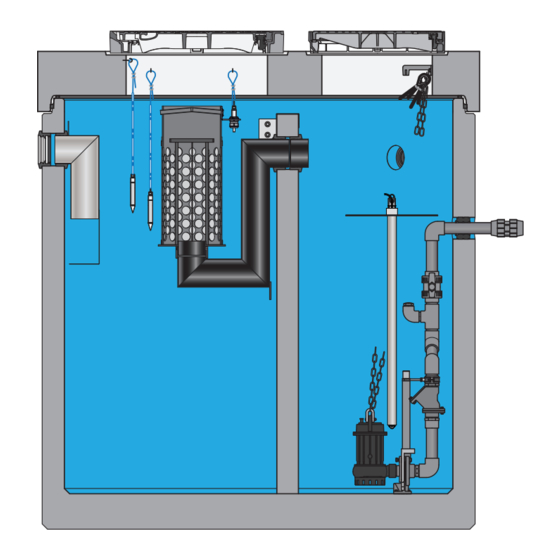
Page 20: Operating Principle
Oleolift-C Product Description 2.4 Operating principle H-AL SDP OFF Separator chamber / Pump station chamber 1 = Light liquid collecting chamber 2 = Sludge collection area 3 = Sampling position (available height at least 160 mm) = Pipe base, backflow loop... -
Page 21: Separator Chamber
The Oleolift-C is a class I light liquid separator (coalescence separator) and has a coalescence insert upstream of the submerged outlet pipe. Due to the surface properties of the material, coarse to finely dispersed light liquids are also separated via the coalescence insert. -
Page 22: Sampling
Oleolift-C Product Description Before recommissioning, the separation chamber must be filled with fresh water again. The sensors mounted in the separator chamber are connected to the idOil-D30 warning system (mounted on a DIN rail in the control unit) and register the following conditions: Oil layer sensor idOil-OIL / 1 reacts to the separating line oil / water at 80 % of the ■... -
Page 23: Pump Station Chamber
Oleolift-C Product Description 2.4.3 Pump station chamber Waste water arising from the separator chamber flows via the submerged outlet pipe and via the inlet pipe protruding over the partition into the pump station chamber at a free gradient. The mounted level sensor (level probe) for the level switching is connected to the control unit. -
Page 24: Product Identification (Type Plate)
Oleolift-C Product Description 2.5 Product identification (type plate) 1 = Year of construction 10 = Type of sludge trap 2 = Product name 11 = Separator chamber volume 3 = Separation compartment 12 = Pump station usable volume 4 = Standard information 13 = Maximum light liquid storage capacity 5 = Approval No. -
Page 25: Installation
13 = On-site pressure pipe 5 = Control unit 14 = On-site cable duct 6 = On-site backflow loop 15 = Oleolift-C 7 = Outdoor cabinet (optional) 16 = Direct extraction (in flow direction right or left) for separator chamber (optional) -
Page 26: Overview Of Earthwork And Installation Works
Oleolift-C Installation Overview of earthwork and installation works Item Work Description Chapter Laying and connecting the on-site inlet pipe 3.3.5 Backfilling the excavation 3.3.12 Installation of shaft components 3.3.4 Mount oil layer sensor idOil-OIL / 1 3.4.5 Mount oil layer sensor idOil-OIL / 2 3.4.5... -
Page 27: Earthworks
Oleolift-C Installation 3.3 Earthworks IMPORTANT Always remove the coalescence insert from the plant and store them safely during the ■ construction stage. Protect the outlet opening of the outlet submersible pipe on site against soiling ■ or pollution. The coating of the tank must be protected against damage, e.g. falling stones, ■... -
Page 28: Digging The Excavation
Oleolift-C Installation Work must be carried out in such a way that no damage is caused to the plant and ■ the pipes and that they remain in their position. Subsequent subsidence of plant components shall be prevented by appropriate measures. -
Page 29: Installation Of Shaft Components
Cover plate, support rings and covers are delivered loose. Shaft components delivered by ACO ■ according to/similar to DIN 4034-1 have an ACO mechanical seal for joint sealing. The mechanical seal is a compression mechanical seal with a wedge-shaped cross section and a factory-made, closed, pre-lubricated slide sleeve. - Page 30 Supporting rings with construction heights from 70 to 210 mm can be optionally purchased from ACO. ATTENTION Produce a maximum of 600 mm with a inside width of 625 mm.
- Page 31 Oleolift-C Installation Clean and moisten the sliding rebate or Î adapter plate and the underside of the supporting ring. Apply mortar bed on the surface of Î the rebate. Insert the supporting ring into the Î centre of the "retainer".
-
Page 32: Laying And Connecting The On-Site Inlet Pipe
Oleolift-C Installation 3.3.5 Laying and connecting the on-site inlet pipe IMPORTANT Before the inlet pipe is connected, the excavations must be filled up to this level, Chapter 3.3.12 “Backfill excavations”. Specifications: Pipe nominal width, Chapter 7.1.1 “Dimensions”. ■ Lay pipes to be frost resistant. -
Page 33: Laying And Connecting The On-Site Blank Cable Pipe
Oleolift-C Installation Use acid-free lubricant to grease the Î spigot end of the ventilation pipe and the sealing lips of the socket seal for the socket pipe. Push the spigot end into the socket pipe. Î 3.3.7 Laying and connecting the on-site blank cable pipe... -
Page 34: Laying And Connecting The On-Site Pressure Pipe
■ Pressure line DN 50, DN 70 or DN 80 (all NS with DL 50) Compression fitting ID 63 mm to ID 75 and 90 can be purchased from ACO as an optional item. Cut the on-site pressure pipe at aright- Î... -
Page 35: Installing On-Site Direct Suction (Optional)
Oleolift-C Installation Pressure line DN 100 (all NS with DL 100) Flange connection dimension according to DIN 2501/PN 16. Connect the on-site pressure pipe with Î the on-site seal and on-site fastening material on the flange. Creating the backflow loop in the pressure pipe Based on the normative requirements, the unit should drain via a backflow loop. - Page 36 Limit the maximum length to the performance of the suction vehicle pump. ■ The following products for creating direct suction can be purchased from ACO as optional components: Direct extraction ■...
- Page 37 Oleolift-C Installation Disposal shaft ■ The following possibilities can be implemented for direct suction: OD 75 mm OD 75 mm OD 90 mm OD 90 mm OD 75 mm OD 90 mm Variant with Variant with street Variant with connection box...
-
Page 38: Installation In The Outdoor Cabinet (Optional)
Use base filler (fill material for reducing the formation of condensation). ■ An outdoor cabinet for accommodating the control unit, fl ashing light, horn, etc. can be purchased from ACO as an optional product. Components such as the control unit, heating, working socket,... are then usually already pre-assembled in the outdoor cabinet. -
Page 39: Leak Test
Oleolift-C Installation An outdoor cabinet for ■ accommodating the backflow loop can be purchased from ACO as an optional product. ACO recommends that the backflow ■ loop is created in PE-HD using mirror-image welding with short- legged bends or in PVC-U in an adhesive process on site. -
Page 40: Backfilling The Excavation
Î marked position. Replace the cover. Î 3.4.2 Installing the submerged pumps Submerged pumps with assembled coupling pieces, cable eyelets, pump pull chains (by the metre) and shackles can be purchased from ACO as an option. 40/ 100... - Page 41 Oleolift-C Installation The connection cable (10 m long) is already connected in the terminal box of the submerged pump in the ready to deliver status, cable type Chapter 7.2 “Submerged pumps”. IMPORTANT Protect the end of the connecting cable against the penetration of moisture.
-
Page 42: Mounting The Level Probe With Protective Pipe
Oleolift-C Installation Protect the end of the submerged pump Î connecting cable against penetrating moisture. Pull the connecting cable upwards (not Î while energised) until it reaches the ● chain holder. Place the loop around the cable eye ( Î... - Page 43 Oleolift-C Installation Plant/NS Longitudinal measurement L [cm] 6-10 / 2500 _ DL 50 1,000 6-10 / 2500 _ DL 100 1,000 6-10 / 3000 _ DL 50 1,000 6-10 / 3000 _ DL 100 1,000 15-30 / 4500 _ DL 100...
- Page 44 Oleolift-C Installation Lift the cover out of the cover frame Î above the pump station chamber and store to the side. Lower the “protective pipe with level Î sensor” unit on the protective pipe into the tank. Guide the protective pipe into the drill Î...
-
Page 45: Assembling Cable Gland
Oleolift-C Installation 3.4.4 Assembling cable gland Figure: Components for cable gland 1 = Threaded connector 8 = On-site blank cable pipe 2 = Clamp 9 = Level probe connection cable 3 = Sealing insert 10 = Cable extension for idOil sensors (e.g. twisted pair cable, 2 x 0.75 mm², unshielded) - Page 46 Oleolift-C Installation IMPORTANT the sealing insert must be positioned tightly on the socket pipe. The sealing insert has 4 drill holes with “placeholders”. Fold open the sealing insert and remove Î "placeholder" (5). Place the connection cable and cable Î...
-
Page 47: Mount Idoil Sensors
Oleolift-C Installation 3.4.5 Mount idOil sensors IMPORTANT To facilitate easy removal of the sensors for cleaning or testing, it is recommended that ■ the sensor cables be sufficiently long and coiled up and fixed in the cover plate. With the build-up sensor (fixed to the holder of the coalescence insert) the complete removal of the coalescence insert with accumulation probe must be guaranteed. - Page 48 Oleolift-C Installation Installation of the idOil-OIL / 1 + 2 oil layer sensors Lift the cover out of the cover frame and Î store to the side (1). Place dowels in the maintenance opening Î of the cover plate and screw in the screw hooks (2).
- Page 49 Oleolift-C Installation Plant/NS OIL / 1 OIL / 2 6-10 / 2500 _ DL 100 1,490 1,440 6-10 / 3000 _ DL 50 1,490 1,440 6-10 / 3000 _ DL 100 1,490 1,440 15-30 / 4500 _ DL 100 1,540...
-
Page 50: Electrical Installation
IMPORTANT Voltage failures caused by longer cable routes must be considered on site. Heating and working socket for the outdoor cabinets and Ex-safety barrier can be obtained from ACO as optional extras. 3.5.1 Overview of the electrical installation work 2 - 5... -
Page 51: Supply Power To The Heater (Optional) And The Power Socket (Optional)
Select the maximum distance according to the length of the connection cables from the ■ submerged pumps and level probe. If required, versions with longer connection cables can be obtained from ACO as optional extras. Installation in the outdoor cabinet Chapter 3.3.10 "Installing the outdoor cabinet (optional) 3.5.4... -
Page 52: Connect The Connection Cable Of The Submerged Pumps
Oleolift-C Installation 3.5.5 Connect the connection cable of the submerged pumps The submerged pump connection cables are 10 m long and are connected in the terminal room of the sub in the as-delivered condition. Type of cable, Chapter 7.2 “Submerged pumps”. -
Page 53: Connect The Cable Extension (Idoil Sensors)
3.5.11 Installing ex-safety-barrier (optional) IMPORTANT If the level sensor is to be utilised in an explosion protected area, then an ex-safety-barrier must be installed. Ex-safety-barrier can be purchased from ACO as an optional component. Ex-safety-barrier must be installed and/ Î... -
Page 54: Operation
Oleolift-C Operation Operation 4.1 Commissioning IMPORTANT A general inspection by a properly qualified, competent person is mandatory before the initial commissioning, Chapter 1.5 "Personnel qualifications". Scope of the general inspection, Chapter 5.3 "5 General inspection of the light liquid separator". -
Page 55: Control Unit
Oleolift-C Operation 4.2 Control unit 4.2.1 Operating and display elements - External control unit I ON 1 = Touch panel 5 = Cam lock 2 = Housing 6 = Ammeter meter P 1 (optional) 3 = Ammeter meter P 2 (optional) -
Page 56: Touch-Panel
Oleolift-C Operation 4.3 Touch-Panel IMPORTANT The display possibilities on the Touch-Panel are varied. The following selection does not claim to be complete. 4.3.1 Main screen _ Overview Time OLEOLIFT Date Overview Detailed view Settings Fault Memory Current level Automatic status... - Page 57 Oleolift-C Operation Operating elements Position Operating field Meaning Explanation Select "Detailed Press the control panel: The display changes to the Detailed view view" page view "Detailed view" page view Select the "Settings" Press the control panel: The display changes to the...
-
Page 58: Page View _ Detailed View
Oleolift-C Operation 4.3.2 Page view _ Detailed view Time OLEOLIFT Date Overview Detailed view Settings Fault Memory PumpControl Please select a page view. 1 = Control panel: Select "Overview" page view 4 = Control panel: Select the "PumpControl" page view 2 = Control panel: Select the "Settings"... - Page 59 Oleolift-C Operation Page view _ Detailed view/ PumpControl Time OLEOLIFT Date Overview Detailed view Settings Fault Memory Pumps Level PumpControl Smallest measured value 0 cm Largest measured value Automatic Automatic 0 cm 0 cm 0.0 h 0.0 h Reset 1 = Display panel: Display smallest measured value...
-
Page 60: Page View _ Settings / System
Oleolift-C Operation Display elements Item Display panel Meaning Explanation Display smallest ... cm Numerical value indicates lowest level level ... cm Display largest level Numerical value indicates largest level ... cm Display current level Numerical value indicates current level Display number of... - Page 61 Oleolift-C Operation 1 = Control panel: Select "Overview" page view 8 = Control panel: Only for ACO service 2 = Control panel: Select "English” operating language 9 = Control panel: Set the time 3 = Control panel: Select the "Detailed View" page view 10 = Display panel: Display Time 4 = Control panel: Select "Deutsch"...
- Page 62 Oleolift-C Operation Display elements Item Display panel Meaning Explanation Display time Numerical values indicate the time Display date Numerical values indicate the date Display station Text shows the designation of the station designation Page view _ Settings / PumpControl / Process...
- Page 63 Oleolift-C Operation Operating elements Item Operating field Meaning Explanation Disable maximum Press the control panel: setting for the maximum operating Deactivate operating time time is disabled Activate maximum Press the control panel: setting for the maximum operating Activate operating time...
- Page 64 Oleolift-C Operation Item Display panel Meaning Explanation Display minimum Numerical value indicates setting of the minimum x cm measuring range measuring range Display maximum Numerical value indicates setting of the maximum x cm measuring range measuring range Display after-running Numerical value indicates setting of the stop delay period...
- Page 65 Oleolift-C Operation 1 = Control panel: select "single pump station" of the 9 = Control panel: Reset operating data for pump 2 pump control unit 10 = Control panel: Reset operating data for pump 1 2 = Control panel: Select preselection "without peak 11 = Control panel: Select operating mode of the float load"...
- Page 66 2 = Control panel: Activate or deactivate alarm message 6 = Control panel: Select the "Functions" page view for Max - Alarm 7 = Control panel: Select the "Process" page view 3 = Control panel: Only for ACO service 4 = Control panel: Enter level settings 66/ 100...
- Page 67 Oleolift-C Operation Operating elements Item Operating field Meaning Explanation Activate or deacti- Activate Press the control panel: Activate or deactivate alarm vate alarm message message during dry running during dry running Deactivate Activate or deacti- Activate Press the control panel: Activate or deactivate alarm...
-
Page 68: Page View _ Fault Memory
Oleolift-C Operation 4.3.4 Page view _ Fault Memory Time OLEOLIFT Date Overview Detailed view Settings Fault Memory Alarm designation Time stamp Malfunction list Minimum level reached (pumps are blocked) 14-07-2020 12:45:52 Pump 1 - Electrical fault 14-07-2020 12:47:21 Minimum level reached (pumps are blocked) - Page 69 Oleolift-C Operation Item Operating field Meaning Explanation Press the control panel: Selected alarm message (4) via the window New entry Name Type Acknowledge alarm Acknowledge Acknowledge description message Close and window after entering name / type / description Select the "Operat-...
- Page 70 Oleolift-C Operation Page view _ Fault memory / Fault memory Time OLEOLIFT Date Overview Detailed view Settings Fault Memory Alarm designation Time stamp Status Malfunction list Minimum level reached (pumps are blocked) 14-07-2020 12:45:52 MESSAGE ON Minimum level reached (pumps are blocked)
- Page 71 Oleolift-C Operation Page view _ Fault memory / operating log Time OLEOLIFT Date Overview Detailed view Settings Fault Memory Name Type Description Malfunction list New entry Fault Memory Time stamp Name Type Description 7 / 14 / 2020 12:46:44 PM...
- Page 72 Oleolift-C Operation Item Operating field Meaning Explanation Select the "Fault Press the control panel: The display changes to the "Fault Fault Memory memory" page view Memory" page view Select the "Malfunc- Press the control panel: The display changes to the Malfunction list tion list"...
-
Page 73: Operating And Display Elements - Internal Control Unit
Oleolift-C Operation 4.3.5 Operating and display elements - Internal control unit DANGER Danger of electric shock due to dangerous electrical voltage There is a danger to life through electric shock when working on the open ■ control unit. During all work, the control unit must always be disconnected from the power supply via the back-up fuse or the main switch and secured against being switched on again. -
Page 74: Settings Before Commissioning
Oleolift-C Operation 4.4 Settings before commissioning 4.4.1 Touch-Panel If no factory settings have been made under the control panels on the touch panel, ■ use the recommended settings from the table. The settings made during the commissioning must be entered in the following ■... -
Page 75: Circuit Breaker
Oleolift-C Operation Touch panel Operat- Recommend- Commissioning Meaning page view ing field ed settings settings Activate or deactivate alarm message during Deactivate dry running Activate or deactivate alarm message for Max Activate - Alarm 72 cm (NS 3-6) Max - Alarm switch-on... -
Page 76: Starting Up The Submerged Pumps
Oleolift-C Operation 4.5 Starting up the submerged pumps IMPORTANT To ensure dry-running protection, the pump chamber of the submerged pump must be vented during the initial start-up. It can be filled with drinking water, rainwater or process water (if it meets the local discharge conditions for effluent). -
Page 77: Executing Pump Station Test Run
Oleolift-C Operation Thread the coupling piece for the Î submerged pump onto the sliding pipe: Position X. Pull the submerged pump at an angle and Î drain further into the water filling. Air escapes from the submerged pump chamber. Lower the submerged pump further Î... - Page 78 Oleolift-C Operation During the trial run, pay attention to the following: Perform the trial run at least twice during commissioning. ■ Perform the trial run with drinking water, rainwater or process water (if it meets the ■ local discharge conditions for effluent).
- Page 79 Oleolift-C Operation When the water reaches the “OFF” level, Pump 2 switches off. OFF or SDP OFF Fill pump station chamber. Î When the water level reaches the “Base load” (BL) level, pump 1 switches on. Increase the inlet flow so that the water Î...
-
Page 80: Requirements For Operation
Oleolift-C Operation Starting automatic mode: Pump 1 Pump 2 Start pump 1 and 2 automatic mode, Î Manual Manual Chapter 4.3.2 "Page view _ Detailed view". Automatic Automatic Close Close Acknowledging a malfunction: New entry Acknowledge fault, Name Î Chapter 4.3.4 "Page view _ Fault Type memory". -
Page 81: Self-Monitoring Of The Light Liquid Separator
Oleolift-C Operation Arrange for the quarterly maintenance of the pump station, ■ Chapter 5.1 "Quarterly maintenance of the pump station". Arrange for half-yearly maintenance of the light liquid separator, ■ Chapter 5.2 "Bi-annual maintenance of the light liquid separator" Arranging for the general inspection of the light liquid separator, ■... -
Page 82: Emptying And Cleaning The Light Liquid Separator
Sensors removed for cleaning must be in their original position after insertion, ■ chapter 3.4.5 "Mounting idOil sensors". Direct extraction for separator chamber can be obtained from ACO as an optional extra. ■ For the purposes of filling the plant, surface water or process water can be used ■... - Page 83 ACO Service as an option, Chapter Introduction “ACO Service”. This will prevent interruptions in operation, as the dirty coalescence insert can be cleaned later. The uncleaned coalescence insert should be stored temporarily in a container which is filled with water or in a plastic bag so that the dirt does not dry firmly in it.
-
Page 84: Cleaning The Coalescence Insert
Oleolift-C Operation 4.9.2 Cleaning the coalescence insert IMPORTANT Checking and cleaning must be carried out immediately when the H-AL raised water ■ level message is signalled. As the switching on of the submerged pumps in the pumping station is blocked by this message, the inflow of waste water into the plant must be prevented until the emptying process. -
Page 85: Operating Log
HP device with maximum 60 bar ■ and at 60° C. Only ever utilise separating-friendly cleaning agents. Obtain recommendations from ACO, Chapter Introduction “Service”. 4.10 Operating log An operating log must be retained and managed in which documents for the respective times and results of the self-monitoring, maintenance, inspections and remedying ot any faults are located, as well as the disposal of removed contents. -
Page 86: Regular Testing, Inspection And Maintenance
Oleolift-C Regular testing, inspection and maintenance Regular testing, inspection and maintenance ACO recommends that you take out a maintenance contract. This therefore guarantees professional and on-schedule completion of the maintenance work by ACO product specialists, Chapter Introduction “ACO Service". Required qualifications for testing, inspection and maintenance, Chapter 1.5 "Personnel... -
Page 87: Half-Yearly Maintenance Of The Light Liquid Separator
Oleolift-C Regular testing, inspection and maintenance 5.2 Half-yearly maintenance of the light liquid separator IMPORTANT Biannual maintenance and inspection (after prior emptying and cleaning) is only ■ permitted by qualified, competent people, Chapter 1.5 "Personnel qualifications" (applies only to Germany. Provisions in other countries can vary). -
Page 88: 5-Year General Inspection Of The Light Liquid Separator
Oleolift-C Regular testing, inspection and maintenance 5.3 5-year general inspection of the light liquid separator IMPORTANT A general inspection (after emptying and cleaning) of the plant must always be executed ■ before initial commissioning and then every 5 years. Only to be executed out by qualified, competent people, Chapter 1.5 "Personnel qualifications"... -
Page 89: Troubleshooting
■ only, Chapter 1.5 "Personnel qualifications". Only use original spare parts. ■ Only have prefabricated pumping station repairs executed by ACO or an ACO ■ Service partner, Chapter Introduction, “ACO Service”. Prevent contact with wastewater and wear protective equipment, ■... - Page 90 Actions Maximum current Power consumption too high Acknowledge malfunction (automatic shut-off) If the malfunction remains: Contact ACO Service High water level Ball valve and/or gate valve Fully open the ball valve alarm in the pressure pipe is not or stop valve in the...
-
Page 91: Technical Data
Oleolift-C Technical data Technical data 7.1 Oleolift-C 7.1.1 Dimensions Ø D3 Ø D4 Ø D1 max. Ø D2 90° ca. 500 45° DN/OD 1 DN 2 91/ 100 45°... - Page 92 Oleolift-C Technical data Ø D1 max. Ø D2 90° ca. 500 45° DN/OD 1 DN 2 45° ca. 150 Dimensions [mm] D3 D4 OD1 DN2 basin 3-6 / 600 2,200 2,450 800 625 1,550 1,580 1,630 ¹ _ DL 50...
-
Page 93: Key Data
Oleolift-C Technical data H3, T and T = Construction height with joints for circular rotating mechanical seal (15 mm) or mortar (10 mm) Basin VL = Ventilation line connection DN 100/OD = 110 mm CC = Cable conduit connection DN 100/OD = 110 mm ¹... -
Page 94: Submerged Pumps
Oleolift-C Technical data 7.2 Submerged pumps Characteristic data and use limits Key data DRG 150/2/50 ex DRG 200/4/100 ex Type of cable for connection cable: 4G1,5 + 3x1 4G1,5 + 3x1 Pump motor operating voltage [V]: Frequency [Hz]: Pump motor speed [1/min.]:... - Page 95 Oleolift-C Technical data DRG 200/4/100 ex H / m DRG 200/4/100 ex ▕◄ Application range ►▏ Scope Q / l/s 95/ 100...
-
Page 96: Shaft Components
Oleolift-C Technical data 7.3 Shaft components Key data Shaft components Extension height [mm] Weights [kg] Supporting ring AR-V 625 Supporting ring AR-V 800 7.4 Manhole covers Class D 400 Weights [kg] Nominal size cpl. Frame Cover 96/ 100... -
Page 97: Control Unit
MultiControl Duo dimensions: incl. cable glands Circuit diagram The complete circuit diagram is enclosed with the control unit and if it is lost it can be re-ordered from ACO Service, Chapter Introduction "Service". 7.5.2 Control unit (separator chamber) /idOil-30 Characteristic data, Assembly and operating instructions for “idOil -30 –... -
Page 98: Appendix: Commissioning Report
Oleolift-C Appendix: Commissioning report Appendix: Commissioning report Commissioning and instruction of a qualified person takes place in the presence of the authorised acceptance inspection representative and the plant operating company. Commissioning date: Handover date: Oleolift-C Oleolift-C_NS Submerged pumps Use location... - Page 99 Oleolift-C Appendix: Commissioning report Check list for commissioning (Qualified person) Two trial runs are required before, during and/or after the commissioning, Chapter 4.5 “Performing a trial run for pump station”. Checks Water seal in separator chamber Electrical fusing of the plant in accordance with the IEC regulations or national and local...
- Page 100 ACO Tiefbau ACO Tiefbau Vertrieb GmbH Am Ahlmannkai D 24782 Büdelsdorf Tel.: + 49 4331 354-500 Fax: + 49 4331 354-358 www.aco-tiefbau.de ACO. creating the future of drainage.
Need help?
Do you have a question about the Oleolift-C and is the answer not in the manual?
Questions and answers