
Related Manuals for ACO NS3/450


Summary of Contents for ACO NS3/450
- Page 1 ACO Environment Oleopator P Oil-Water Separator Installation Operation Maintenance...
-
Page 2: Table Of Contents
Oleopator P Series ACO Oleopator P is a range of oil Contents separators that allow sediments and oils to be separated out simultaneously Oleopator P Series in one tank. Separator systems are System Components available with a range of different sludge and oil capacities to suit specific site 1. -
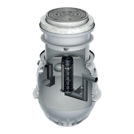
Page 3: System Components
ACO ENVIRONMENT System Components Light Duty Heavy Duty 1. Cover 9. Inlet Pipe 2. Load Distribution Plate* 10. Baffle Plate 3. Extension Shaft 11. Tank 4. Identification Plate 12. Outlet Pipe 5. Coalescence Unit 13. Sampler Connection 6. Float 14. Outlet Connection 7. -
Page 4: Safety Considerations
Safety Considerations The safety guidelines in this chapter are to be read before using the separator. Serious injuries or death could occur as a result of misuse. 1.1 DESIGNATED USE Limitations Areas of Application The separators are not to be installed for Oleopator separators are designed residential wastewater. -
Page 5: Qualifications Of Personnel
Only repair faults yourself if They must not be used as steps, the measures are described in these footholds or resting places for cleaning operating instructions. Contact ACO equipment etc. for all other measures. The separator system is defined as a „... -
Page 6: Installation
Installation 2.1 ONSITE HANDLING Oleopator P separators are intended for in-ground installation. Care must be Personnel taken to determine correct installation to take into account site loadings and traffic Carry separator with two people using patterns. Details are provided for both the circular ring as a grip and pipe light duty and heavy duty applications. -
Page 7: Ground Conditions
ACO ENVIRONMENT 2.2 GROUND CONDITIONS 2.3 SEPARATOR POSITIONING Where groundwater is present, certain The purpose of a separator is to collect additional measures may need to be light oils for proper disposal. Timely taken to prevent lifting. emptying and maintenance is critical for effective operation. - Page 8 2.3 SEPARATOR POSITIONING (cont.) INSTALLATION SITUATION Super-Elevated Positioning Alarm System Ready for use Normal operation Normal operation Max Oil = Float Closure = Blockage Oil will leak from cover Alarm will signal and oil will leak from cover Backflow from sewer Oil will leak from cover Alarm will signal and oil unless a backflow...
- Page 9 ACO ENVIRONMENT INSTALLATION SITUATION Super-Elevated Positioning Alarm System Ready for use Normal operation Normal operation Max Oil = Float Closure = Blockage Oil will stay in separator, Alarm will signal and oil wastewater will flood from will stay in separator,...
-
Page 10: Installation
2.4 INSTALLATION Light Duty Installations Heavy Duty Installations 1. Excavate area 60" (1524 mm) wider 1. Excavate area 60" (1524 mm) wider and 12" (305 mm) deeper than the and 12" (305 mm) deeper than the separator; this allows for a 12" (305 separator;... - Page 11 ACO ENVIRONMENT Typical Reinforcement Plan Load Distribution Plate Ø 53.15"/25.60" x 8.00" (1350 mm/650 mm x 203 mm) Concrete: 5,000 psi (35 MPa) Concrete Steel: #4 Rebar (10 M) Concrete Cover: 1.18" (30 mm) (3) #4 Rebar (top) (35) #4 Rebar @ Ø...
-
Page 12: Initial Set-Up
Initial Set-Up/Commissioning 3.1 PRIOR TO FILLING THE SYSTEM Ensure all required air and water Identification plate provides: „ tests are completed before finished installation of unit. Separator type identification „ All system components—baffles, „ Nominal size „ coalescence units and internal piping— Class „... -
Page 13: Filling Separator System
ACO ENVIRONMENT 3.2 FILLING SEPARATOR SYSTEM System MUST NOT be filled until Filling Procedure „ installation is complete and all 1. Ensure inlet and outlet valves are mortared and sealed joints have been open. allowed to cure properly. 2. Fill the separator with clean water, System should be cleaned before use. -
Page 14: Operation
Operation ACO Oleopator P is designed to be easy to operate with minimal intervention required. 4.1 ENTERING THE SEPARATOR 4.2 OIL/SLUDGE LEVEL SENSORS All relevant local accident prevention An optional alarm system makes regulations must be strictly observed operation easier and ensures compliance when entering a separator. -
Page 15: Maintenance
ACO ENVIRONMENT Maintenance 5.1 MAINTENANCE SCHEDULE Table below provides a recommended schedule of maintenance and inspection to ensure trouble-free operation of the separator. Note: Refer to 4.1 Entering the Separator (pg 13) before maintenance is undertaken. What must Who should... -
Page 16: Cleaning Coalescence Units
5.2 CLEANING COALESCENCE UNITS Removing Coalescence Mats Coalescence unit must be removed Coalescence mats are attached to a periodically for cleaning. The separator is supporting basket at the top and bottom not functional during this process. of the coalescence unit with tensioners and Velcro strips (fluffy side outwards). -
Page 17: Oil/Sludge Disposal
ACO ENVIRONMENT 5.3 OIL/SLUDGE DISPOSAL 5.4 GENERAL INSPECTION Maximum levels for emptying the Prior to initial use and thereafter at separator are when: regular five-year intervals, a properly qualified technician* must inspect 80% of maximum oil storage has been the separator to ensure it is in good „... -
Page 18: Alarms Assembly & Initialization
ACO Separators ACO Separ Alarms Assembly & Initialization Instructions Alarms Assembly Instructions 6.1 FITTING POSITION OF SENSOR SUPPORT The illustrations below depict correct fitting position of sensor support with separators 1 Fitting position of sensor support without and with top system. The sensor cables or the extension cables (optional) are laid up to the monitoring device through an in-situ empty tube. -
Page 19: Sensor Setting
ACO ENVIRONMENT 6.2 SENSOR SETTING les. The illustration below depicts the completely mounted sensors. The detail shows the ON Do not mount support above inlet extension of the sensor cable; also see hanging instructions in the idOil-30 Installation and Maintenance Manual. The height of the sensors is relative to the upper edge of the inlet pipe and must be set per the table and diagram below. -
Page 20: Simple Commissioning
6.3 SIMPLE COMMISSIONING (MANDATORY) To initialize alarm, a commissioning procedure must be followed: 1. Connect all required sensors. ACO Separators 2. Power up alarm unit. 3. Press sensor identification button on panel. on Instructions oning (Mandatory) procedure must be followed: utton on panel. -
Page 21: Advanced Commissioning
ACO ENVIRONMENT ACO Separators tion Instructions 6.4 ADVANCED COMMISSIONING (OPTIONAL) Advanced commissioning allows the operator to perform the following actions: Set Date/Time „ Add Unit Name „ Access Alarm Log sioning (Mandatory) „ ning procedure must be followed: Advanced commissioning is performed as follows:: sors. -
Page 22: Askaco
We help you to find the right answer. ACO on the web You will find further information for our products on the ACO USA website. This allows you to access technical data, images, specifications, and installation instructions. www.acousa.com 888-490-9552... - Page 23 ACO products are designed and planning and implementation stages, we produced to last. With our after-sales advise and support you on a project- support, we ensure that ACO will specific basis. exceed your standards for years to come. www.askACO.us 888-490-9552...
- Page 24 It is the customer's responsibility to ensure that each product is fit for its intended purpose and that the actual conditions of use are suitable. ACO, Inc. reserves the right to change products and specifications without notice.
Need help?
Do you have a question about the NS3/450 and is the answer not in the manual?
Questions and answers